KROHNE 7300C 调频雷达操作手册
7300C QS科隆料位计

"7300C QS" 菜单编号步骤功能功能描述可选项默认值A.0 快速设置A.1 设置模式A.1.1 完成依次完成快速设置全过程,其中包括:安装设置、空频谱、转换、输出A.1.2 安装设置罐和介质的相关参数1 安装类型罐体的材质金属罐、塑料罐、户外应用金属罐2 罐高/测量距离罐高是设置从仪表法兰下端面或螺纹连接的上根部到罐底的距离。
测量距离(仅用于户外应用)是设置仪表的最大测量距离。
范围:0.2…80m/0.564…262ft 20m/65.61ft3A应用类型仪表用于何种工况。
如果介质表面平静,选择“存储”。
如果介质表面波动,选择“处理”。
如果介质表面被搅动及漩涡、泡沫,选择“搅拌”。
如果仪表安装在导波管中,请选择“+导波管”存储、处理、搅拌、存储+导波管、处理+导波管、搅拌+导波管处理或处理+导波管当安装类型选择为户外应用时。
如果介质表面平静,选择“无干扰”。
如果介质表面波动,选择“中等干扰”。
如果介质表面有气泡、漩涡和泡沫,选择“严重干扰”。
无干扰、中等干扰、严重干扰无干扰4A导波管直径当步骤3A中选择“+导波管”时。
在此处设置导波管直径。
范围:8…200mm/0.31…7.88" 100mm/3.94"4B 导波管高度当步骤3A中选择“+导波管”时。
在此处设置导波管高度。
范围:0…80m/0…197ft 10m/32.81ft5 死区距离由用户设置仪表不可测量的区域。
推荐至少在天线以下100mm/4"天线延长管(C.1.6)…罐高(C.1.2) ①②6 安装设置总览7 继续之前,必须保存或取消对当前设置的更改保存、删除③保存A.1.3 空频谱固定干扰或活动部件产生干扰信号。
空频谱记录这些干扰信号。
当仪表测量物位时,会滤除这些已记录的干扰信号。
1 你的储罐是否完全充满了?当储罐充满时,无法记录空管的干扰信号频谱。
使用空频谱时,罐内必须是部分充满或全空。
KROHNE科隆雷达液位计
KROHNE科隆雷达液位计OPTIWA VE 6300 C用于固体测量的非接触式雷达(FMCW)液位计(咨询请拨dǎ:1580²²²5061²²²213)科隆超声波物位计OPTISOUND3010/3020/3030、科隆雷达物位计OPTIFLEX1100/1300 BM702 BM102 OPTIW AVE6300/7300、科隆磁翻板液位计BM26、科隆磁致伸缩液位计KMR、科隆电磁流量计OPTIFLUX2100/4100/2300/4300、科隆质量流量计OPTIMASS1300C、科隆流量开关DW181/182/183/184、科隆金属转子流量计H250 DK32 DK37、科隆玻璃转子流量计DK800 V A40 GA24等•一个转换器适合于所有类型的天线(聚四氟乙烯(PTFE)/聚丙烯(PP)材质的水滴型天线,喇叭型天线)•多尘条件下准确测量的唯一保证•独特的水滴型天线设计用于多尘的环境OPTIWA VE 6300 C是一款采用调频连续波(FMCW)测量原理的非接触式雷达液位计;可广泛应用于测量粉末、粒子等固体介质的距离、物位及体积,也可用于测量液体介质。
与采用脉冲测量原理的雷达物位计相比,即使在多尘的应用场合中,也可以稳定测量。
当满足仪表过程连接处的温度要求时,介质温度的高低不影响测量。
特点•标准精度±10mm/±0.4"•聚四氟乙烯或聚丙烯材质的水滴型天线,用于多尘的场合中可有效防止挂料•最高可耐过程连接处200°C / 390°F及40 bar / 580 psig•最大量程可达80 m / 260 ft•通过加装天线延长管,可以适应不同的安装短节高度•标配PACTware和DTM调试软件•可选第二路电流输出•带有触摸键的显示屏可方便调试仪表•通过显示屏上的安装向导来正确设置仪表参数,可提高对不平整表面的测量准确性行业•矿产•化工•食品•钢铁及冶金•造纸及纸浆应用•储仓•筒仓•料斗OPTIWA VE 7300 C液体物位测量的雷达解决方案•适用于液体测量•在困难条件下准确测量的唯一保证•为特定目的而设计的天线选择(水滴型,卫生型等)OPTIWA VE 7300 C是采用调频连续波(FMCW)测量原理的非接触式雷达物位计,可广泛应用于测量液体、浆料、糊状物的距离、物位及体积。
K波雷达物位成像仪-26G调试说明书

10 0 1 (d
选择物料性质为微 DK 时,一般用于介电常数小于 1 . 4 ,这时介质表面的直接回波很弱, 或不能测量,而通过罐底反射的方法可以测得料位高度这时需要输入以下参数中的两个: 1 .空罐空高,空罐或空容器的空高值 。 2 .真实料高或待测物质的介电常数 ,这两参数关联 ,输入其中之一即可 。以上参数 的精度直接影响测量结果的精度值注 : “微 DK”的选择要慎重,大多测量是不合适 的,当 “微 DK”选择后,系统根据回波情况,判断采用直接回波法或底部反射法来得 到测量结果 。 1-4 阻尼时间 为抑制因液面波动起伏引起的测量显示的变化跳动, 可设定适当的显示阻尼时间 (范围 在 0~999 秒) ,既保证有足够的测量响应时间,又能使传感器在延时后反映出变化的测 量值。一般设定几秒的时间就足以使测量值稳定显示。 当液晶显示菜单号为 1-3 时 ,按 阻尼时间 6S 1-4 键 ,进入阻尼时间设置菜单,液晶显示如下图:
当液晶显示菜单号为 1-2 时,按 物料性质 液体
键进入“物料性质 1-3”,液晶显示如下: 1-3
再按
键进入“物料性质 1-3”,液晶显示如下: 物料性质 液体 固体 微 DK 1-3
液体 1-1-3 物位快速进入“物位快速变化 1-1-3”,液晶显示如下图:
键 ---选择编程项 ---选择参数位置 ---列出选项
键 ---进入编程状态 ---确认编程项 ---确认参数修改
1
[26G 调试说明书]
(二) 四个按键的简单说明
菜单结构参见总框图。图中向右横箭头的过渡由 键实现; 键实现横箭头的向左过渡 。 键实现;向下的箭头过渡由
仪表在按
键进入编程主菜单项 。每个参数编辑完成后须用
奥麦斯操作维护手册7300(面向用户)
前言 (1)1安全 (1)1.1 总则 (1)1.2 个人安全 (1)1.4设备安全 (2)1.5电气安全 (2)1.6压力系统安全(气压和液压) (2)1.7焊接安全 (3)1.8设备的起吊安全 (3)1.9破碎机安全检查程序 (3)1.10安全连锁操作 (3)1.11振动保护 (3)2工作原理 (4)2.1破碎产品料径的控制 (4)3了解破碎机结构 (5)3.1破碎机的外部结构 (5)3.2破碎机的内部结构 (7)3.4转子及耐磨件 (7)4启动程序 (8)4.1启动之前 (8)4.2初始启动 (9)4.3破碎机初始给料 (9)4.3运行 (10)4.4噪音等级 (10)4.5振动 (10)4.6物料流量 (10)4.7粉尘排放 (10)4.8 给料控制 (10)4.9 旁路溢料控制 (10)5停机程序 (11)5.1停机 (11)6检查和维修 (11)6.2润滑 (12)6.3注油要求 (12)6.4推荐润滑油品 (12)6.5轴承箱 (12)6.6运行温度 (12)6.7润滑油的排放 (12)7转子维修 (13)7.1 途径 (13)7.2 清洗转子 (13)7.3 转子抛料头组件 (13)7.4上下耐磨板的拆卸 (15)7.5分料盘 (16)7.6给料筒 (17)7.7导料板 (18)7.8转子本体 (20).8转子积料 (22)8.1 首要功能 (22)8.2 次要功能 (23)9转子调整 (23)9.1转子积料的调整 (24)10转子拆卸 (25)10.1转子安装 (26)11转子平衡 (29)11.1 转子平衡机的组装 (29)11.2 平衡步骤 (30)11.3 转子平衡故障诊断 (31)12维修 (31)12.1 破碎腔积料 (31)12.2 破碎腔壁(低积料), (32)12.3 过度积料 (32)12.4 破碎腔筋肋板 (32)12.5 趾板 (33)13.1 腔环 (33)13.2 受料仓 (33)13.3 受料仓仓体 (34)13.4 控制盘 (34)13.5 液压调节控制闸板门 (34)13.6 液压缸 (35)14.破碎机维修 (36)14.1 给料筒的对中及高度调整 (36)14.2 耐磨裙环 (37)14.3 安全连锁 (38)14.4 振动开关 (38)14.5 检查门和舱口 (38)14.6 破碎机机座及排料溜槽 (38)14.7 机座衬板 (39)14.8 机座耐磨护板 (39)14.9 润滑脂排泄槽 (40)14.10 皮带护罩 (40)14.11 电机 (40)14.12 轴承箱 (40)14.13 轴承箱密封 (41)14.14 从机座拆卸轴承箱 (41)14.15 在机座上安装轴承箱 (43)14.16驱动皮带张紧力 (44)15螺栓扭矩参考表 (46)前言奥麦斯破碎机是一种高质量立轴冲击式破碎机,具有许多独具特色,新颖、先进的设计,使用户取得高效、可靠的运行效果,生产质量稳定的产品。
科隆krohne OPTISWITCH 3000系列 外部壳件 补充说明书
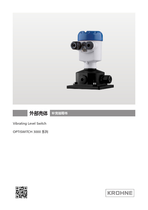
外部壳体Vibrating Level Switch OPTISWITCH 3000 系列目录48879-ZH-210419目录1关于本技术文献 ............................................................................................................................................31.1 功能 .............................................................................................................................................................................31.2 对象 .............................................................................................................................................................................31.3 所用的图标.. (32)安全注意事项 ...............................................................................................................................................42.1 授权人员 .....................................................................................................................................................................42.2 正确使用 .....................................................................................................................................................................42.3 用于防爆区域的安全说明 . (43)产品说明 ......................................................................................................................................................53.1 结构 .............................................................................................................................................................................53.2 工作原理 .....................................................................................................................................................................83.3 仓储和运输.. (84)安装 .............................................................................................................................................................94.1 一般性说明.................................................................................................................................................................94.2 安装准备 .....................................................................................................................................................................94.3 安装步骤 .....................................................................................................................................................................94.4 安装 - 外部壳体 (仪表壳体). (105)将传感器与外部壳体相连接 ........................................................................................................................115.1 为连接作准备...........................................................................................................................................................115.2 接线步骤 ...................................................................................................................................................................116 调试 ...........................................................................................................................................................126.1 调试 ...........................................................................................................................................................................127 维护 ...........................................................................................................................................................137.1 需要维修时的步骤 .. (138)拆卸 ...........................................................................................................................................................148.1 拆卸步骤 ...................................................................................................................................................................148.2 废物清除 . (149)附件 ...........................................................................................................................................................159.1 技术参数 ...................................................................................................................................................................159.2 尺寸 (16)编辑时间: 2021-04-131 关于本技术文献48879-Z H -2104191 关于本技术文献1.1 功能应将随附的附加说明书与仪表的使用说明书一起使用。
IC-7300中文说明书

使用说明书HF /50 MHz 电台北京和瑞信通科技有限公司感谢您购买这款Icom产品。
IC-7300 HF/50 MHz电台运用了Icom最先进的技术和工艺进行设计和制造。
有了您的精心呵护,这款产品将为您提供长期的无故障运行。
我们赞赏您选择了IC-7300 HF/50 MHz电台,并期望您赞同Icom公司“科技为先”的理念,花些时间深入了解IC-7300电台的设计。
重要提示在使用电台之前,要仔细完整地阅读全部说明书。
保存本说明书-本说明书包含有IC-7300的基本操作说明,完整的操作说明参见附带光盘中的完全版操作说明书。
特点•射频直接采样系统IC-7300采用了射频直接采样系统。
射频信号直接转换为数字数据并在FPGA中处理。
这个系统是当代业余无线电领域的领先技术。
•实时频谱频谱功能采用了最先进的分辨率、扫描速度和动态范围技术。
当触摸频谱屏幕上的预定信号时,触摸区域将被放大。
大型的4.3英寸彩色TFT触摸液晶屏提供了更直观的操作。
•最新的“IP+”功能最新的IP+功能可以提高第三拦截点(IP3)的性能。
当接收邻频强干扰的弱信号时,优化的AD转换器将改善信号失真。
•领先的RMDR和相位噪声特性相比IC-7200,RMDR提高97dB(典型值),相位噪声特性也提高了15dB(1 kHz分离度)。
•4.3英寸彩色触摸屏•内置自动天调•便于设置的多功能旋钮关键字的定义危险!警告!随机配件保险丝保险丝(5A)(25A)手咪(HM-219)直流电源线ACC插头(3米)(13芯)CW电键插头保险丝(6.35毫米立体声)(30A)扬声器插头(3.5毫米立体声)直流电源线光盘欧洲版○i根据电台的版本可能会提供不同的配件或不提供。
本产品包含RTO“RTX”软件,并获得软件许可。
本产品包含“zlib”开放源码软件,并获得开放源码软件许可。
本产品包含“libpng”开放源码软件,并获得开放源码软件许可。
FCC相关信息•关于B类非故意辐射:本设备已经过测试,符合FCC规则第15部分关于B 类数字设备的限制。
科隆电磁流量计、雷达物位计安装操作指导
确保单相流体,在液体中不允许存在大量气泡和固体颗粒。 可允许气体含量≤5% / 可允许固体含量≤70%(纸浆、矿浆、泥浆) ——载体仍然是导电液体,需要调整设置(开启滤波) 根据法拉第电磁感应定理,只有介质为导体时,才会产生电动势。
9
| YYYY-MM-DD | Presentationtitle
安装注意事项
安装要求的原则
• 避免两相介质(或非导电介质) • 保证流态 • 避免干扰
10 | YYYY-MM-DD | Presentationtitle
安装注意事项
前后直管段要求
前5DN,后2DN(至少) 前10DN,后5DN(推荐)
前后直管段从电极处开始计算
11 | YYYY-MM-DD | Presentationtitle
安装注意事项
前后直管段要求:T形三通
12 | YYYY-MM-DD | Presentationtitle
安装注意事项
安装要求的原则
• 避免两相介质(或非导电介质) • 保证流态 • 避免干扰
13 | YYYY-MM-DD | Presentationtitle
安装注意事项
磁场
法拉第电磁感应定理决定了磁场干扰会引起非正常测量
52 | YYYY-MM-DD | Presentationtitle
调试设置
快速设置
进入A1.5输出 输出功能液位/距离/容量 4mA设置 20mA设置 电流范围4-20mA 故障处理保持 HART地址:0
保存
快速设置完毕,退出保存
53 | YYYY-MM-DD | Presentationtitle
测量范围
•液位是更大的信号 •蓝色钻石 •黄色钻石
KROHNE FMG7 0B Series 磁导化流量传感器操作手册说明书
FMG70B SeriesMagnetic Inductive Flow Sensor- 2 -M-5575/0416Table of contents page 0About this operating manual (4)1Device description (5)1.1Delivery, unpacking and accessories (5)1.2Intended use (6)1.3Exclusion of liability (6)2Safety instructions (7)3Construction and function (8)4Installation of FMG70B (9)4.1Installation instructions (9)4.2Mounting (10)5Electrical connection (11)5.1Wirings (12)6Commissioning and measuring mode (13)6.1Commissioning (13)6.2Switching on and off (13)6.3Measuring mode (13)7Maintenance and cleaning (15)7.1Return shipment to the manufacturer (15)8Disassembly and disposal (16)9Technical data (17)9.1Characteristics FMG70B (17)9.2Materials table (18)9.3Pressure drop (18)9.4Temperature limits (19)9.5Dimensions (20)Copyright notice:The reproduction, distribution and utilization of this operating manual as well as the communication of its contents to others without express authorization is prohibited. Offenders will be held liable for the payment of damages. All rights reserved in the event of the grant of a patent, utility model or design.Technical changes reserved - 3 -About this operating manual- 4 - M-5575/04160 About this operating manual• The operating manual is aimed at specialists and semi-skilled personnel.• Before each step, read through the relevant advice carefully and keep to the specified order.•Thoroughly read and understand the information in the section "Safety instructions".If you have any problems or questions, please contact your supplier or contact us directly at:One Omega Drive, P.O. Box 4047Stamford, CT 06907-0047 Tel: (203) 359-1660 e-mail:**************Hazard signs and other symbols used:WARNING! / CAUTION! Risk of injury!This sign indicates dangers that cause personal injuries that can lead to health defects or cause considerable damage to property.CAUTION! Electric current!This sign indicates dangers which could arise from handling of electric current.CAUTION! Material damage!This sign indicates actions which could lead to possible damage to material or environmental damage.ADHERE TO OPERATING MANUAL! NOTICE!This symbol indicates important notices, tips or information. NO DOMESTIC WASTE!The device must not be disposed of together with domestic waste.Pay attention to and comply withinformation that is marked with this symbol.Follow the specified instructions and steps.Adhere to the given order.❑Check the specified points or notices.Reference to another section, document orsource. • Item.Device descriptionTechnical changes reserved - 5 -1 Device descriptionThe FMG70B series from Omega, is a non-contact flow sensor. The measurement is performed using magnetic induction and works without any moving parts.The FMG70B is used for measuring or metering water and aqueous solutions. The compact design and independence from the intake and discharge sections allows the FMG70B to be used under a variety of conditions.Versions ∗:The FMG70B is available with inner diameters 0.39 in narrows to 0.16 in, 0.39 in and 0.79 in.The versions can be configured differently (♑ FMG70B data sheet).Type plate:The type plate sticker is located at the bottom side of the FMG70B.It contains the most important data, the connection diagram and the arrow for the flow direction (Example ♑ Fig.).1.1 Delivery, unpacking and accessoriesAll units have been carefully checked for their operational reliability before shipment.❒ Immediately after receipt, please check the outer packaging for damages or any signs ofimproper handling.❒ Report any possible damages to the forwarder and your responsible salesrepresentative. In such a case, state a description of the defect, the type and the serial number of the device.Report any in-transit damage immediately. Damage reported at a later date shall not be recognized. Unpacking:Carefully unpack the unit to prevent any damage.Check the completeness of the delivery based on the delivery note. Scope of delivery:❒ 1x FMG70B as ordered.❒1x Operating manual. ❒ 1x Packing.∗Customised versions available on request.Device description- 6 - M-5575/0416IMPORTANT!Use the type plate to check if the delivered unit corresponds to your order.In particular, for devices with electrical components, check to see if the correct power supply voltage is specified.Accessories:❒ Connection cable with moulded M12x1 couplingsocket.❒ M12x1 coupling socket as component.1.2 Intended useThe magnetic inductive flow sensor FMG70B must only be used for measuring and metering liquids with a minimum conductivity of 50 μS/cm.WARNING! No safety component!The magnetic inductive flow sensor of the series FMG70B is not safety components in accordance with Directive 2006-42-EC (Machine Directive). Never use the FMG70B as a safety component.The operational safety of the device supplied is only guaranteed by intended use. The specified limits (♑ § 9 "Technical data") may under no circumstances be exceeded.Before installing the device, check that the wetted materials of the device are compatible with the media being used (♑ § 9.2 "Materials table").Measuring tube empty (or partially filled). / Conductivity too low.The green LED may blink irregularly if the measuring tube of the FMG70B is empty or partially filled or if the conductivity of the fluid being used is too low. Random impulses will be present at the output, but they do not represent an actual flow.Ensure that the measuring tube of the FMG70B is always completely filled (♑ § 4.1 "Installation instructions").Ensure that the conductivity of the fluid is at least 50 μS/cm.1.3Exclusion of liabilityWe accept no liability for any damage or malfunctions resulting from incorrect installation, in-appropriate use of the device or failure to follow the instructions in this operating manual.Safety instructionsTechnical changes reserved - 7 -2Safety instructionsBefore you install the FMG70B, read through this operating manual carefully. If the instructions contained within it are not followed, in particular the safety guidelines, this could result in danger for people, the environment, and the device and the system it isconnected to.The FMG70B correspond to the state-of-the-art technology. This concerns the accuracy, the operating mode and the safe operation of the device.In order to guarantee that the device operates safely, the operator must act competently andbe conscious of safety issues.Omega provides support for the use of its products either personally or via relevant literature. The customer verifies that our product is fit for purpose based on our technical information. The customer performs customer- and application-specific tests to ensure that the product issuitable for the intended use. With this verification all hazards and risks are transferred to our customers; our warranty is not valid.Qualified personnel:The personnel who are charged for the installation, operation and maintenance of the FMG70B must hold a relevant qualification. This can be based on training or relevanttuition.The personnel must be aware of this operating manual and have access to it at all times.The electrical connection should only be carried out by a fully qualified electrician. General safety instructions:In all work, the existing national regulations for accident prevention and safety in the workplace must be complied with. Any internal regulations of the operator must also becomplied with, even if these are not mentioned in this manual. Degree of protection according to EN 60529:Please ensure that the ambient conditions at the site of use does not exceed the requirements for the stated protection rating ( § 9 "Technical data").Prevent freezing of the medium in the device with appropriate measures.Only use the FMG70B if it is in perfect condition. Damaged or faulty devices must be checked without delay and, if necessary, replaced.When fitting, connecting and removing the FMG70B use only suitable appropriate tools. Do not remove or obliterate type plates or other markings on the device, as otherwise the warranty is rendered null and void. Special safety instructions:Warnings that are specifically relevant to individual operating procedures or activities can be found at the beginning of the relevant sections of this operating manual.Construction and function- 8 - M-5575/04163 Construction and functionComponents:① Housing:The housing consists of aluminum die casting and has the IP65 degree of protection.② Electrical connection:The electrical connection is made via 5-pin plug M12x1.③ Operation / flow indicator LED.④ Process connection:The process connections are available in different sizes.⑤ Type plate (sticker).Construction:The measuring tube with its earthing sleeves and electrodes passes through the housing and forms the external process connection of the FMG70B.A magnetic field for the measurement process is generated inside the sensor housing, which also contains the sensor and signal conditioning circuitry.The two stainless steel electrodes are located in the middle of the measuring tube between the earthing sleeves. The FMG70B does not need any moving parts to make measurements. The inside of the measuring tube is completely open, allowing the fluid to flow unhindered through the measuring tube.Function:The magnetic inductive flow sensor operates in accordance with the principle of induction, i.e. a DC voltage is generated by the movement of a conductor in a magnetic field:The measuring tube of the FMG70B is located in a magnetic field (B).An electrically conductive liquid (Q) flows through the measuring tube. The positive and negative charge carriers are deflected in opposite directions. A voltage perpendicular to the magnet field is generated and picked up by the two electrodes. The resulting induced voltage is proportional to the mean flow velocity of the liquid.The electronics of the FMG70B converts the induced voltage to a flow-proportional frequency signal.Installation of FMG70BTechnical changes reserved- 9 -4 Installation of FMG70BBefore installing, check that❒ the wetted materials of the device are suitable for the liquid being used ( § 9.2"Materials table").❒ the equipment is switched off and is in a safe and de-energized state. ❒ the equipment is depressurized and has cooled down.SUITABLE TOOLS:Use only suitable tools of the correct size.4.1 Installation instructionsCAUTION! Risk of malfunction due to external magnetic fields!Magnetic fields close to the device can cause malfunctions and should be avoided.Ensure that no external magnetic fields are present at theinstallation site of the FMG70B.•The FMG70B can always be installed anywhere along the pipeline. Straight sections of piping are preferable, however.Installation of FMG70B- 10 - M-5575/0416• Installation can occur in horizontal and vertical pipes. The flow sensor is only suitable for application in completely filled pipe systems.•As a matter of principle magnetic inductive flow sensors are widely independent from the flow profile. An inlet section is not absolutely necessary.To reach a most highly accuracy of the measurement, you should use straight inlet and outlet sections according to the inner diameter. The inlet section has to be at least10 x inner diameter; the outlet section 5 x inner diameter in order to achieve the specified accuracy.• The inlet and outlet sections and gaskets must have the same or a slightly larger inside diameter than the measuring tube in order to achieve the specified accuracy.4.2 MountingThe FMG70B is installed directly into the pipeline. The compact design and light weight of the unit make wall-mounting unnecessary.IMPORTANT NOTICES:• Observe the flow direction indicated on the FMG70B.• Observe the mounting dimensions (♑ § 9.5 "Dimensions").Select an appropriate location for installation (♑ § 4.1"Installation instructions").To ensure the best possible measuring accuracy, a vertical installation position with increasing flow is preferable (no collecting of dirt deposits).Wrap the FMG70B connections with 1 to 2 wraps of threadtape (e.g. Teflon ® tape).Wrap tape in a clockwise direction, viewed form the end, leaving the first two threads uncovered.Make sure the tape does not intrude into the flow path.Attach the FMG70B with arrow pointed in the direction of flow. The fittings should be screwed into FMG70B hand tight.CAUTION! Material damage!Do not use excessive force. The FMG70B can be damaged.While tightening, counter the union nut on the hexagon of the process connection!If you do not counter it, the FMG70B can be damaged!Use two wrenches to tighten the FMG70B an additional ¾ to 1 turn.When tightening, use a wrench (AF 1.063 or AF 1.338) to counter the process connection on the hexagon (flange) in place.Electrical connection5 Electrical connectionThe electrical connection of the FMG70B is via the 5-pin plug M12x1 at the top of the housing.The wiring of the FMG70B depends on the ordered version. A distinction is made between frequency and analog output, as well as basic and optional wiring.CAUTION! Electric current!The electrical connection should only be carried out by a fully qualified electrician. De-energize the electrical system before connecting the FMG70B.CAUTION! Material damage and fire hazard!Exceeding the specified limits will cause damage to the electronics. Without current limiting, there is a fire hazard due to overheating of the device. Connect the FMG70B only to a power source with limited power.Optional wirings:Depending on the version, an analog output can be optionally connected.Connecting cable:Suitable connection cables with molded coupling socket are available in various lengths included in the range of Omega accessories. The shielding is already connected with the knurled nut.IMPORTANT! Shielding required!Use only shielded connection cables.The shield of the connection cable should not be connected to earth.We recommend to ground the pipes directly before and behind the FMG70B (♑ Figure).IMPORTANT NOTICE:Pay attention to the temperature resistance of the connecting cable (♑ § 9 "Technicaldata") at high media temperatures.If the temperature resistance is smaller than the medium temperature, the cable may notbe directly laid on the pipe.Connection 5-pin plug M12x1:Screw the coupling socket of the connection cable to the plug of the FMG70B. Tighten the knurled nut of the coupling socket with a maximum torque of 1 Nm.Electrical connection5.1 WiringsPinout:The pinout differs according to the chosen configuration of the device.M12x1Possible pinout: Pin 1: +U BPin 2: n. c. (not connected) / Analog U/I Pin 3: GNDPin 4: FrequencyPin 5: n. c. (not connected) / d. n. c. (do not connect)Connect the connecting cable according to your version and the pinout on the type plate.Supply voltage:FMG70B with frequency output:Push-Pull *1:NPN Open Collector:PNP Open Collector:*1: Push-Pull switching outputs of several FMG70B may not be connected in parallel. *2: Recommendation Pull-Up / Pull-Down resistance R L ~5 k ΩUse of frequency and analog output:Recommendation for resistance R ~5 k ΩCommissioning and measuring mode6 Commissioning and measuring modeBefore switching on the FMG70B for the first time, please follow the instructions in the following section.6.1 CommissioningCheck that❒the FMG70B has been installed correctly and that all screw connections are sealed.❒the electrical wiring has been connected properly.❒the measuring system is vented by flushing.6.2 Switching on and offThe FMG70B has no switch and can therefore not be switched on and off independently. Switching on and off takes place via the connected supply voltage.Switch on the supply voltage.goes into measuring operation.6.3 Measuring modeIn measuring mode, the green LED flashes proportional to the measured flow.frequency of ~30 ... 40 Hz.In that case the green LED seems to be lit permanently.The following subsections only apply to devices which have the correspondent functionality.ing subsections only apply to devices which have the correspondent functionality.FMG70B with frequency output:The FMG70B provides according to the version a flowproportional NPN, PNP or Push-Pull square wavesignal.The frequency of the pulse output changes accordingto the flow ( Fig.).Commissioning and measuring mode FMG70B with analog output:According to the configuration of theFMG70B, the analog output provides a voltage or current signal.This signal is proportional to the measured flow.Maintenance and cleaning7 Maintenance and cleaningMaintenance:The FMG70B is maintenance-free and cannot be repaired by the user. In case of a defect, the device must be replaced or sent back the manufacturer for repair.CAUTION! Material damage!When opening the device, critical parts or components can be damage. Never open the device and perform any repair yourself.Cleaning:Clean the FMG70B with a dry or slightly damp lint-free cloth. Do not use sharp objects or aggressive agents for cleaning.7.1 Return shipment to the manufacturerDue to legal requirements placed on environmental protection and occupational safety and health and to maintain the health and safety of our employees, all units returned to Omega for repair must be free of toxins and hazardous substances. That also applies to cavities in the devices. If necessary, the customer must neutralize or purge the unit before return to Omega.Costs incurred due to inadequate cleaning of the device and possible costs for disposal and/or personal injuries will be billed to the operating company.WARNING! Risk of injury due to insufficient cleaning!The operating company is responsible for all damages and harm of any kind, in particular physical injuries (e.g. caustic burns or toxic contaminations), decontamination measures, disposal etc. that can be attributed to insufficient cleaning of the measuring instrument. Please follow the instructions for sending in returns shown on page 23 of this manual.The following measures must be taken before you send the unit to Omega for repair:Clean the device thoroughly. This is of extreme importance if the medium is hazardous tohealth, i.e. caustic, toxic, carcinogenic or radioactive etc.Remove all residues of the media and pay special attention to sealing grooves and slits. Attach a note describing the malfunction, state the application field and thechemical/physical properties of the media.Please specify a point of contact in case our service department has any questions.Disassembly and disposal8 Disassembly and disposalCAUTION! Risk of injury!Never remove the device from a plant in operation.Make sure that the plant is shut down professionally.Before disassembly:Prior to disassembly, ensure that❒ the equipment is switched off and is in a safe and de-energized state. ❒ the equipment is depressurized and has cooled down. Disassembly:Remove the electrical connectors.Remove the FMG70B using suitable tools.Disposal:NO HOUSEHOLD WASTE!The FMG70B consists of various different materials. He must not be disposed of with household waste.Take the FMG70B to your local recycling plantTechnical data9 Technical dataThe technical data of customized versions may differ from the data in these instructions. Please observe the information specified on the type plate.9.1 Characteristics FMG70B*2 factory setting.*3 other range on request.Technical datathe FMG70B.9.2 Materials table9.3 Pressure dropFMG71B and FMG72B: FMG73B:Technical data 9.4 Temperature limitsThe maximum ambient temperature depends on the medium temperature and the version of the FMG70B.Technical data9.5 DimensionsFMG71B and FMG72B:¾'' NPT only for FMG72B.The cross section of the FMG72B does not taper to 0.16 in.FMG73B:For your notes For your notesFor your notesFor your notesM-5575/0416。
KROHNE 7300C 调频雷达操作手册
ktek一体式超声波操作手册
QUICK START for the KSONIK MICRO 4W and LP
Initially the default unit of measurement (meters) must be changed to feet. Refer to page 5 for the method of changing parameters and select “ft” in the “Unit” parameter, “ENTER” it and press “RUN” KSONIK MICRO was designed with a very simple configuration program. This allows the technician to set up KSONIK MICRO without the aid of a complicated source codebook. There are no references to any codes in KSONIK MICRO. The set up procedure is all menu driven. KSONIK MICRO 4W WIRING CONNECTIONS Simply connect up a regulated Power Supply (20 - 30 V DC) to the connector block on the right side of the display, the POSITIVE supply to positive terminal and the NEGATIVE supply to negative terminal. The ANALOG signal (4 - 20 mA) is measured on positive and negative terminals on the left hand side connector. NOTE: The power supply and analog signal share a common NEGATIVE (-) supply in the 3W configuration. KSONIK MICRO LP WIRING CONNECTIONS Simply connect the regulated power supply to positive and negative terminals. A multi-meter can be placed in series with the positive supply to measure the mA output.
- 1、下载文档前请自行甄别文档内容的完整性,平台不提供额外的编辑、内容补充、找答案等附加服务。
- 2、"仅部分预览"的文档,不可在线预览部分如存在完整性等问题,可反馈申请退款(可完整预览的文档不适用该条件!)。
- 3、如文档侵犯您的权益,请联系客服反馈,我们会尽快为您处理(人工客服工作时间:9:00-18:30)。
1. 安全须知...................................................................................................................................... 3 2. 安装.............................................................................................................................................. 5
2.4.1 通用要求................................................................................................................. 8 2.4.2 导波管/旁通管中的安装....................................................................................... 8 2.4.3 如何安装天线延长管............................................................................................. 9 2.4.4 如何旋转及拆卸仪表转换器............................................................................... 10 3. 电气连接.................................................................................................................................... 11 3.1 安全须知........................................................................................................................... 11 3.2 输出 1 和输出 2................................................................................................................ 11 3.2.1 非防爆(Non-Ex).............................................................................................. 12 3.2.2 本质安全型防爆(Ex ia)................................................................................ 12 3.2.3 隔爆型防爆(Ex d).......................................................................................... 12 3.2.4 PROFIBUS PA........................................................................................................ 13 3.2.5 FOUNDATION Fieldbus........................................................................................ 13 3.3 防护等级........................................................................................................................... 13 4. 启动............................................................................................................................................ 14 4.1 启动前的检查................................................................................................................... 14 4.2 仪表的操作方法............................................................................................................... 14 5. 设置............................................................................................................................................ 15 5.1 用户权限........................................................................................................................... 15 5.2 显示操作面板的使用....................................................................................................... 15 5.2.1 面板的布局........................................................................................................... 15 5.2.2 按键的功能........................................................................................................... 16 5.2.3“帮助”功能........................................................................................................ 16 5.3 操作员模式....................................................................................................................... 16 5.4 管理员模式....................................................................................................................... 17 5.4.1 功能概述............................................................................................................... 17 5.4.2 如何进入管理员模式........................................................................................... 17 5.4.3 菜单功能............................................................................................................... 18 5.4.4 如何使用“空频谱”功能来消除干扰信号....................................................... 27 5.4.5 如何测量凹形或锥形罐底................................................................................... 28
2.1 仪表用途............................................................................................................................. 5 2.2 供货范围............................................................................................................................. 5 2.3 安装位置............................................................................................................................. 6 2.4 对于液体测量的特别推荐................................................................................................. 8