级联多电平变换器电压平衡算法
第三章级联多电平变频调制算法研究

基于 DSP 的单元串联多电平变频技术的研究
(b) 载波水平移相(移位)PWM 调制 (b) Carrier wave vertical shift PWM modulation 图 3.3 移相(移位)PWM 调制驱动和输出波形图 Figure 3.3 Carrier wave shift PWM modulation 通过图 3.3(b)可以看出,载波水平移相 PWM 调制的本质是,对每个功率单元进行 SPWM 调制, 通过载波的移相,使得每个功率单元输出的 SPWM 脉冲相互错开(其基波相位相同),这样在叠加后, 可以得到多电平输出,并使得等效开关频率大大提高,改善了输出波形。采用移相 PWM 调制之所以能 够得到这样好的效果,是因为在结构上多重化的结果。可以预见,如果在对每个功率单元进行 SPWM 调制时,各载波不移相,那么每个功率单元的输出 SPWM 波将是相同的,在叠加之后仅仅是 PWM 脉 冲的幅值增大了,电平数和等效开关频率都不会增加。因此,载波移相是水平移相 PWM 调制的根本所
在理想情况下,M 值可在 0~1 之间变化,以调节逆变器输出电压的大小。实际上,M 总是小于 1 的,在 k c 较大时,一般取最大值的 M=0.8~0.9 。
§3-2 单元串联中压变频器移相 PWM 调制
单元串联的中压变频器通过功率单元串联的形式输出中压, 单元的串联(多重化)既使得改善输出波 形成为可能, 同时也带来了如何分配各功率单元输出功率的问题。 这就需要一种合理的 PWM 调制方法, 既使得输出波形谐波最小,同时又可以为各功率单元均匀分配输出功率。于是,单元串联中压变频器移 相 PWM 调制得以提出。 载波水平相移 SPWM 技术可以在较低的开关频率下实现较高开关频率的效果, 使 SPWM 技术应用 于大功率场合成为可能,而且在提高装置容量的同时,有效地减少输出谐波,提高整个装置的信号传输 带宽。
级联型多电平变换器构成及控制方法

Project No. 3Report for High Power ConversionSystemsProject Title: Cascade multi-level converter and its controlmethodStudent Name:Email Address: @Phone No.Date: 2012.6.15Signature:级联型多电平变换器构成及控制方法初探浙江大学电气工程学院【摘要】本文介绍了级联型多电平变换器的一般构成方法,并对构成原则进行了初步的讨论并提出了新型级联型拓扑结构。
本文又对级联型多电平的控制策略进行了初探。
最后,本文提出一种改进型级联多电平变换器,并对其进行了简要分析。
【关键字】级联多电平控制方法Cascade multi-level converter and its control method( , College of Electrical Engineering , Zhejiang University)Abstract: This article describes the general composition of the cascade multi-level converter, and constitutes the principle of a preliminary discussion. It also proposes a new cascade topology and cascaded multi-level control strategy . Finally, this paper presents an improved cascaded multilevel converter and makes a brief analysis.Key words: cascade, control strategy, multi-level1.多电平变换器多电平变换器技术是一种通过改进变换器自身拓扑结构来实现高压大功率输出的新型变换器,它无需升降压变压器和均压电路。
级联型电力电子变压器电压与功率均衡控制方法

电 工 技 术 学 报
TRANSACTIONS OF CHINA ELECTROTECHNICAL SOCIETY
Vol.31 Nov.
No. 22 2016
级联型电力电子变压器电压与 功率均衡控制方法
王杉杉 王玉斌 林意斐 于程皓
济南
李厚芝
(山东大学电气工程学院 摘要
国家自然科学基金( 51277115 、 51177095 )和山东省自然科学基金( ZR2011EEM026 )资助项目。 收稿日期 2016-04-06 改稿日期 2016-06-06
第 31 卷第 22 期
王杉杉 等
级联型电力电子变压器电压与功率均衡控制方法
93
0
引言
作为一种新型的电能转换设备,与级开关频率的 提高,在一个开关周期内实时准确地计算流经每个 DAB 模块的功率,将变得更加困难,因此深入研究 DAB 级的无电流传感器功率均衡更有现实意义。 文 献 [11,12]提出整流级采用共同占空比控制,DAB 级 采用电压跟随控制,在 DAB 级参数相同的情况下, 可以达到很好的效果。然而该法忽略了参数不匹配 问题,对于因参数不匹配导致的电压、功率不均衡 问题有待更深入的研究。文献 [13] 提出整流级采用 电压均衡控制, DAB 级采用无电流传感器的功率均 衡控制,即 DAB 级在采用共同占空比控制的基础 上,利用 PI 调节器产生各 DAB 模块占空比的微调 量,对各 DAB 模块的占空比进行调节,从而改善 因参数差异导致的功率不均,但因存在静态误差而 有待完善。 针对上述问题,本文提出了在整流级采用电压 均衡控制, DAB 级采用一种新颖的无电流传感器的 功率均衡控制方法,充分考虑了因 DAB 参数不匹 配导致的功率不均衡问题。基本思路为采用各整流 模块占空比的有功分量作为反馈量,利用算法来实 现对各 DAB 模块占空比的调节,从而达到功率均 衡的目的。因为不需要电流传感器,易于在 DSP 中 实现,避免了使用电流传感器实现功率均衡时对开 关频率的限制, 降低了系统的成本以及电路复杂度。
级联五开关H桥多电平逆变器功率均衡控制方法

级联五开关H桥多电平逆变器功率均衡控制方法叶满园;康翔【摘要】为了提高逆变器的电压和功率等级,提出了一种级联五开关H桥多电平逆变器拓扑结构的功率均衡控制方法.该方法采用了同相交错层叠锯齿载波移相调制,综合了同相层叠锯齿载波调制良好的消谐特性以及载波移相调制各个单元功率分配均衡的优点,使级联五开关H桥多电平逆变器拓扑结构中各个功率单元不仅可以输出五电平,保持良好的消谐特性,而且可以在一个输出周期内实现功率均衡.以3个功率单元为例,进行了仿真实验.实验结果验证了该拓扑结构及其控制方法的可行性与优越性.%A power balance control scheme of cascaded multilevel inverter with five switches for each H-bridge unit is proposed in this paper to improve the voltage and power levels of the inverter. Phase disposition modulation and phase-shift modulation are adopted,which has advantages of both good harmonic characteristics owing to phase disposition modulation and power balance distribution for each H-bridge unit owing to phase-shift modulation. The proposed scheme can not only output five levels that have good harmonic characteristics,but also achieve the output power bal-ance in one output cycle for each cell. A cascaded inverter consisting of three cells is taken as an example in the simula-tion,and the result verifies the validity and superiority of the proposed topological structure and its control scheme.【期刊名称】《电力系统及其自动化学报》【年(卷),期】2017(029)002【总页数】5页(P27-31)【关键词】五开关H桥;同相层叠;锯齿载波;移相调制;多电平逆变器;功率均衡控制【作者】叶满园;康翔【作者单位】华东交通大学电气与自动化工程学院,南昌 330013;华东交通大学电气与自动化工程学院,南昌 330013【正文语种】中文【中图分类】TM464级联多电平逆变器是中压大功率传动系统中应用最为广泛的逆变器拓扑结构之一[1-3],有相电压冗余、谐波含量低、易于模块化设计制造等优点。
H 桥级联多电平变流器的直流母线电压平衡控制策略--上交大

第32卷第6期中国电机工程学报V ol.32 No.6 Feb.25, 201256 2012年2月25日Proceedings of the CSEE ©2012 Chin.Soc.for Elec.Eng.文章编号:0258-8013 (2012) 06-0056-08 中图分类号:TM 46 文献标志码:A 学科分类号:470·40H桥级联多电平变流器的直流母线电压平衡控制策略王志冰1,于坤山2,周孝信2(1.上海交通大学电子信息与电气工程学院,上海市闵行区 200240;2.中国电力科学研究院,北京市海淀区 100192)Control Strategy for DC Bus Voltage Balance in Cascaded H-bridge Multilevel ConvertersWANG Zhibing1, YU Kunshan2, ZHOU Xiaoxin2(1. School of Electronic Information and Electrical Engineering, Shanghai Jiao Tong University, Minhang District, Shanghai 200240,China; 2. China Electric Power Research Institute, Haidian District, Beijing 100192, China)ABSTRACT: The converter based on cascaded H-bridge multilevel topology is a nonlinear multiple variable and strong coupling system, in which the DC bus voltage balancing problem of single power module affects the output performance of similar equipment seriously, moreover restricts its applications. This paper analyzed the power exchanging relationship between converters and power systems in detail, and obtained a control law, which can balance the single phase dc bus voltage by controlling negative sequence currents, or zero sequence voltages, or negative sequence voltages of the converter. Combining the global average DC voltage control and the single module DC voltage control, the paper presented a universal three-step decoupling control strategy, which based on the separated positive and negative sequence currents, and which can solve the DC bus voltage balancing problem of cascaded H-bridge multilevel converters. In addition, it can improve the output capability of converters. The validity and feasibility of special DC bus voltage control strategy is verified by simulation results and experimental results.KEY WORDS: cascade H-bridge multilevel converter; static synchronous compensator (STATCOM); three-phase three-wire power system; positive and negative sequence current separating; DC bus voltage balance control摘要:H桥级联多电平变流器是一个非线性、多变量、强耦合系统,其中单个功率模块的直流母线电压平衡问题严重影响该类型装置的输出性能,并限制其应用范围。
一种新型的级联逆变器电容电压平衡控制方法

一种新型的级联逆变器电容电压平衡控制方法崔灿【摘要】级联逆变器在光伏系统中应用非常广泛,其控制的一个主要难点就是直流侧电容电压平衡问题。
以5电平级联多电平逆变为研究对象,提出一种新型的电容电压平衡控制方法,并在仅有电压平衡控制和附加了MPPT控制两种条件下进行了仿真研究。
研究结果表明,在稳态条件下,逆变器直流侧电容电压稳定,各桥之间电容电压基本一致,逆变器输出电流电压稳定,并且具有控制简单、可靠性高、调节速度较快等优点,具有较高的应用价值。
%Cascaded inverters are now widely used in the photovoltaic systems.One of the main difficulties of controlling it is balancing the voltage of the DC capacitors.This paper puts forward a new control method for DC voltage balance based on 5-level cascaded inverter. We do simulations in the condition of the system with voltage balancing control and then added by MPPT.It is indicated in the result that the strategy is performing well during the steady state.Due to that the values of the H bridge voltage are steady and almost the same,the output of the inverter is stable.Better is that the method is simple,reliable and can quickly response,which may lead to high application value.【期刊名称】《电气自动化》【年(卷),期】2016(038)004【总页数】4页(P21-23,29)【关键词】级联逆变器;直流电容;电压平衡;电压调制比;最大功率点跟踪【作者】崔灿【作者单位】安徽省电力设计院,安徽合肥 230601【正文语种】中文【中图分类】TM722级联多电平逆变器是由若干个基本逆变单元(H桥)通过串联连接而成的。
第四章级联型多电平中高压变频器的控制算法和控制策略
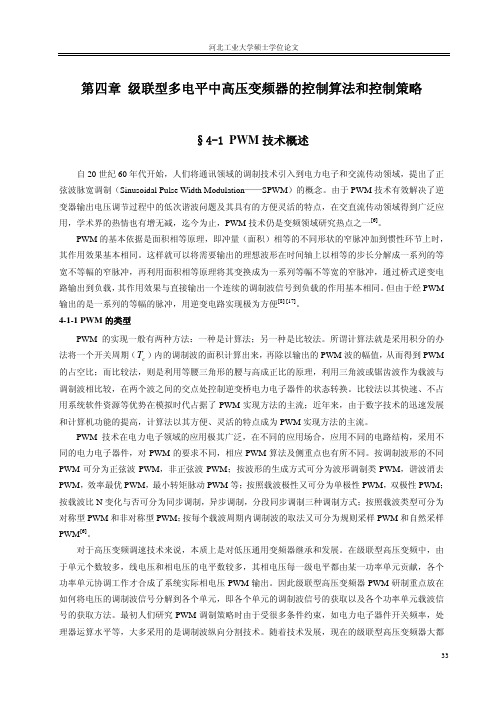
第四章级联型多电平中高压变频器的控制算法和控制策略§4-1 PWM技术概述自20世纪60年代开始,人们将通讯领域的调制技术引入到电力电子和交流传动领域,提出了正弦波脉宽调制(Sinusoidal Pulse Width Modulation——SPWM)的概念。
由于PWM技术有效解决了逆变器输出电压调节过程中的低次谐波问题及其具有的方便灵活的特点,在交直流传动领域得到广泛应用,学术界的热情也有增无减,迄今为止,PWM技术仍是变频领域研究热点之一[6]。
PWM的基本依据是面积相等原理,即冲量(面积)相等的不同形状的窄脉冲加到惯性环节上时,其作用效果基本相同。
这样就可以将需要输出的理想波形在时间轴上以相等的步长分解成一系列的等宽不等幅的窄脉冲,再利用面积相等原理将其变换成为一系列等幅不等宽的窄脉冲,通过桥式逆变电路输出到负载,其作用效果与直接输出一个连续的调制波信号到负载的作用基本相同。
但由于经PWM 输出的是一系列的等幅的脉冲,用逆变电路实现极为方便[8] [17]。
4-1-1 PWM的类型PWM的实现一般有两种方法:一种是计算法;另一种是比较法。
所谓计算法就是采用积分的办T)内的调制波的面积计算出来,再除以输出的PWM波的幅值,从而得到PWM 法将一个开关周期(c的占空比;而比较法,则是利用等腰三角形的腰与高成正比的原理,利用三角波或锯齿波作为载波与调制波相比较,在两个波之间的交点处控制逆变桥电力电子器件的状态转换。
比较法以其快速、不占用系统软件资源等优势在模拟时代占据了PWM实现方法的主流;近年来,由于数字技术的迅速发展和计算机功能的提高,计算法以其方便、灵活的特点成为PWM实现方法的主流。
PWM技术在电力电子领域的应用极其广泛,在不同的应用场合,应用不同的电路结构,采用不同的电力电子器件,对PWM的要求不同,相应PWM算法及侧重点也有所不同。
按调制波形的不同PWM可分为正弦波PWM,非正弦波PWM;按波形的生成方式可分为波形调制类PWM,谐波消去PWM,效率最优PWM,最小转矩脉动PWM等;按照载波极性又可分为单极性PWM,双极性PWM;按载波比N变化与否可分为同步调制,异步调制,分段同步调制三种调制方式;按照载波类型可分为对称型PWM和非对称型PWM;按每个载波周期内调制波的取法又可分为规则采样PWM和自然采样PWM[6]。
级联H桥型多电平STATCOM的直流电压平衡分析和仿真
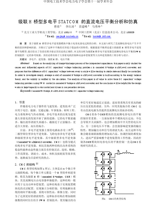
级联H桥型多电平STATCOM的直流电压平衡分析和仿真曹靖1李红涛1苗建峰2马秀坤11) 北方工业大学机电工程学院,北京100144 2)中国工控网(北京)信息技术公司,北京1000891) Email:caojing@2) Email:hontel@摘要基于级联H桥型多电平逆变器模块中独立电容充放电过程的分析,本文深入研究了直流侧电容电压产生不平衡的原因和影响因素,并探讨了这种不平衡的差异趋于稳态的可控特性,根据能量平衡理论建立的级联H桥型多电平逆变器平均模型,最后给出了仿真结果并验证其结论的正确性。
本文的分析为级联H桥多电平逆变器直流侧电容电压平衡的PWM 控制提供一定的参考依据,其结论将有助于大容量电机控制和动态补偿装置等大功率逆变器的工程分析与设计。
关键词多电平,逆变器,级联H桥,电压平衡Abstract Based on the analyzing of charge-discharge process of the independent capacitance, this paper mainly studied the causes and influential aspects of DC capacitors’voltage balancing problems in cascaded H-bridge multi-Level converter, and proposes that the difference of DC capacitors’ voltage between every module will be tending to stable state and finally be controlled. In order to investigate deeply, average model of cascaded H-bridge multi-Level converter is built according to the energy balance theory, and the validity is verified by the simulation. The analysis of this paper is of value to solve these DC capacitors’ voltage balancing problems using PWM control in cascaded H-bridge multi-Level converter, and the conclusion will be helpful for the design works in large-capacity motor control and dynamic compensation devices.Keywords Cascaded-H Bridge, Multi-Level Converter, DC capacitor voltage balancing1.引言伴随着电力电子器件的飞速发展,逆变技术广泛应用于电信、能源、交通运输、军事装备、材料工程、电力系统和电气传动领域。
- 1、下载文档前请自行甄别文档内容的完整性,平台不提供额外的编辑、内容补充、找答案等附加服务。
- 2、"仅部分预览"的文档,不可在线预览部分如存在完整性等问题,可反馈申请退款(可完整预览的文档不适用该条件!)。
- 3、如文档侵犯您的权益,请联系客服反馈,我们会尽快为您处理(人工客服工作时间:9:00-18:30)。
Abstract—Voltage-balancing controller in cascaded multilevel converters has been discussed extensively in previous literatures where several effective methods have been proposed. The coupling effect between a voltage-balancing controller and the original system controller is however not addressed comprehensively. This paper proposes a new voltage-balancing controller for single-phase cascaded multilevel converters in a d-q coordinate. The theoretical finding shows that the proposed method can effectively eliminate the coupling between two controllers in both steady and dynamic state. Simulation and experimental results validate the proposed method.Index Terms—cascaded multilevel converter, voltage balance, d-q control, decouple controlI. I NTRODUCTIONHE multilevel converters are appealing solutions for high voltage applications since it is generally difficult to utilize a single power semiconductor to switch directly[1]. Cascaded multilevel converters have gained considerable attention recently compared with other multilevel topologies due to its advantages in terms of modularization, extendibility, and minimization of power semiconductors [1]-[28]. It has been proposed and widely employed in high voltage and high power applications such as inverters in AC motor drives, static synchronous compensators (STATCOM), and active power filters (APF) [4]-[9]. Another attractive application is to use this topology as a bidirectional active rectifier because of the available distinct dc links feeding separate loads [10]. It can reduce the harmonic distortion at the AC side and provide satisfactory regulation for all DC links. A good application example is the solid-state transformer (SST), which is reported in [11]. DC capacitor voltage imbalance is an inherent problem for both multilevel converter systems and multi-pulse converter systems [12]-[13]. In a cascaded multilevel converter, this can be caused by mismatch of active and passive components, different switching pattern, control resolutions, and different loads (operating as a rectifier) [7], [10]. The imbalance of the DC capacitor voltage will lead to degradation of the input current, imbalance of loss in each H-This work was supported National Science Foundation under Award EEC-0812121.Xu She, Alex Q.Huang, Gangyao Wang, and Fei Wangare with Future Renewable Electric Energy Delivery and Management Systems Center, North Carolina State University, Raleigh, NC 27695, USA (e-mail: xshe@, aqhuang@, gwang3@, fwang5@).Tiefu Zhao is with Eaton Corporation, 4201 North 27th street, Milwaukee, WI 53261, USA (tzhao@)Wenxi Yao is with Zhejiang University, Hangzhou, ZJ 310027, China (email: ywxi@) bridge, and even collapse of the whole system (over voltage, over current, etc) [14]. The basic requirement for a DC voltage-balancing controller is to balance the DC link voltages under all operation conditions. While a good DC voltage-balancing controller should also be simple, fast, and easily expanded to a cascaded converter with N H-bridges. Besides, the reactive power should be controlled independently of the active power, thus it can be possibly equally distributed in each H-bridge cell according to the requirement. Furthermore, the voltage-balancing controller should couple with the original system controller as less as possible. The last point emphasized here requires for a control system that can be separated into two decoupled layers. The upper layer only control the total DC voltage and the lower layer only eliminate the voltage difference among H-bridges.In this paper, a new voltage-balancing controller is proposed to reduce the coupling effect between the voltage-balancing controller and the original system controller for a single-phase cascaded multilevel converter. A single-phase d-q model is firstly established with consideration of DC voltage imbalance. Then the coupling term between two controllers is identified and a control scheme is proposed to eliminate it. Comparisons between the proposed method and previous methods are conducted. Furthermore, DC voltage-balancing controller reference generation techniques are discussed and proved to be of big impact to the DC voltage balance during the start up process. A suitable reference is then chosen to get rid of this undesired impact. Simulations and experiments are provided to validate the theoretical findings.II. A VERAGE M ODELING IN D-Q C OORDINATE CONSIDERINGV OLTAGE I MBALANCEFig.1 (a) shows the configuration for a single-phase cascaded multilevel rectifier with N H-bridges.sv is the point ofcommon coupling (PCC) voltage,sL is the boostinductor,sR is the equivalent resistor of the inductor ,wire, andlosses.iC andiR( 1...=i N) are DC capacitors and loads in each DC output. N H-bridges are series connected tosynthesize a 2N+1 level waveform, which isabv, from N isolated DC voltage sources, which are denotedas1−dc dcNv v.( 1..., 1...4)==aijT i N j denotes the switches in the converter.A New V oltage-balancing Controller inCascaded Multilevel Converters Xu She, Student Member, IEEE, Alex Q.Huang, Fellow, IEEE, Gangyao Wang, Student Member,IEEE, Tiefu Zhao, Member, IEEE, Fei Wang, and Wenxi YaoT1R(a) Topology of original N H-bridges cascaded rectifierR R R2mN T T(b) Topology of N H-bridges cascaded rectifier with hypothesized phaseFig. 1 Topology for cascaded rectifier with N H-bridgesDifferent from the three-phase system, N imaginary H-bridges, which lag 900 with the original N H-bridges, have to be hypothesized in order to realize the single-phase d-q transformation [29]. This is illustrated in Fig. 1 (b). The inductor current in the real and hypothesized cascaded H-bridges are represented as s i and m i while the PCC voltage for the hypothesized converter is m v . (1..., 1...4)==mij T i N j denotes the switches in the hypothesized converter. The relationship between s v and m vis shown in Fig. 2. The detailed theory of the single-phase d-q transformation can be found in [29].Fig. 2 Relationship between values in real and hypothesized circuitsThe average modeling in d-q coordinate considering the voltage imbalance can be obtained as:1212121(...)s sd sd sd d d dN s dc dc dcN q q qN s s ss s sq sq sq s R d w i i v d d d L v v v dt d d d d R L L L L i v w dt L −⎛⎞⎡⎜⎟⎡⎡⎢⎥⎡⎤⎡⎤⎡⎤⎜⎟=+−+++⎢⎥⎢⎥⎢⎥⎢⎥⎢⎥⎢⎥⎜⎟−⎢⎥⎢⎥⎢⎥⎣⎦⎣⎦⎣⎦⎣⎦⎣⎦−⎜⎟⎢⎥⎣⎦⎝⎠(1)( 1...)dci dcidi sd qi sq iidv v d i d i C i N dt R +=+= (2) In the cascaded multilevel inverter application, the reactive current is controlled to a certain value for reactive power compensation (such as in STATCOM and APF). In the active rectifier application, the reactive current is controlled to zero to obtain unity power factor. The DC capacitor voltage is regulated by the active current. Fig. 3 demonstrates the d-q coordinate dual loop control for a cascaded multilevel rectifier with N H-bridges. In Fig. 3, NE is the total DC voltage reference, base V is the base value of the PCC voltage, and base I is the base value of the input current. ed H ,id H ,iq H arethe controllers for the DC bus voltage, active current, and reactive current respectively. The dq-am transformation and the d-q decoupling control can be found in [29], which is similar with the classical d-q decoupling control in a three-phase system. PCC voltage feed-forward control is also implemented so that the distortion of the grid voltage will not affect the controller since only the L-type filter is adopted in this paper. In the DC voltage loop, a notch filter at 120Hz is added to the feedback loop to eliminate the second harmonic component in the DC capacitor voltages by assuming that the grid frequency is 60Hz. If the controller only considers the DC capacitor voltages balanced condition and only controls the total DC voltages, it is called the original system controller in this paper. If the system is unbalanced, certain modification has to be made for active component of duty cycles, which are 1d Δ,2d Δ, …n d Δ, as shown in dotted arrow, and these are given by an additional voltage balancing controller. Since the total DC voltage is already regulated by the original system controller, only N-1 additional DC voltage control loop can be added. If the duty modification of the last one is not well designed, this additional voltage-balancing controller is coupled with original system controller. The effort of this paper is to minimize the coupling effect between the original system controller and the voltage balancing controller as such they can be designed separately.III. A N EW V OLTAGE B ALANCING C ONTROLLER WITH M INIMUM E FFECT T O THE O RIGINAL C ONTROLLER A. Theoretical AnalysisDC voltage in each capacitor may become imbalanced for many reasons such as different loads connected to each DC port. Although the total voltage is still controlled by the original system controller, the unequal distribution of voltage among H-bridges exists. Active power should be re-distributed among H-bridge modules in order to achieve voltage balance.+v 1s dref−idH −/s wL NE/s wL NEΔΔs d v v si 1/s baseI +++−−+θFig. 3 D-q coordinate controller for N H-bridges cascaded multilevel converterThe dynamic equation for the original system controller can be described by (3), where d d and q d are active and reactive duty cycle generated by it. The average voltage of each DC output is assumed to be E , which should be selected as the reference for the DC voltage balance controller as shown in (4). This will be further explained in detail in part IV. sd s s sd s sq sd dsqss sq s sd sq q diL R i wL i v N dtdi L R i wL i v N Ed dt=−++−=−−+− (3)1Ndci i N E v ==∑ (4)When DC voltages become imbalanced, voltages in DC ports are denoted as ( 1...)dci v i N = and ,( 1...)di qi d d i N = are the modified duty cycles. The dynamic equation for the system becomes:11Nsd s s sd s sq sd dci dii N sqss sq s sd sq dci qi i diL R i wL i v v d dt di L R i wL i v v d dt ===−++−=−−+−∑∑ (5) This can be rewritten as:11()()Nsd s s sd s sq sd d d dci di i N sqs s sq s sd sq q q dci qi i diL R i wL i v N Ed N Ed v d dt di L R i wL i v N Ed N Ed v d dt ===−++−+−=−−+−+−∑∑(6)Comparing equation (6) with (3), it is clear that1()Nd dci di i N v d =−∑ and 1()Nq dci qi i N v d =−∑are the additional termsadded by the voltage balancing controller. If an advanced modulation strategy is adopted, these two terms will be zero since duty cycles are not modified. However if feedback closed loop regulation is adopted, duty cycle is modified for each H-bridge thus making the first term unequal to zero. The key strategy in this paper is to eliminate this additional term so that the voltage-balancing controller will not affectthe pre-designed original system controller. Define the coupling index as follows:22111()(()())NNd di dci d d i dci i i J N Ed d v N Ed d d E v ===−=−+Δ−Δ∑∑(7)221()Nq qi dci i J N Ed d v ==−∑ (8)Where, i d Δis the modification of duty cycle and dci v Δis the error between the reference and the feedback voltage for each DC output.Since the reactive duty cycle are not modified and this means q qi d d =. (8) is already zero since E is chosen as shown in (4). The problem of how to minimize 1J can be achieved if equation (9) is satisfied.1()()Ndi dci d i dd E v N Ed =+Δ−Δ=∑ (9)Expand (5) further leads to:1111NNNNd d dci i i dci d i i i i d E d v d E d v N Ed ====−Δ+Δ−ΔΔ=∑∑∑∑ (10)Equation (10) can be simplified as:111()()NN Ndcii dci i dci d i i i E vd v d v d ===−ΔΔ=Δ=Δ∑∑∑ (11)Since there are altogether N DC voltages needed to becontrolled and the total DC voltage has already been regulated by the original system controller, only N-1 closed loop regulator can be added in order to ensure the stability of the control system. Without losing generality, the modifications of duty cycles for the first N-1 H-bridges are generated by a PI controller, thus to eliminate the difference between the feedback value and the reference value.()()( 1...1)i pi dcref dci ii dcref dci d k v v k v v i N Δ=−+−=−∫ (12) Then the modification of active duty cycle in Nth H-bridge should meet (13) in order to minimize the coupling effect.111NN dci d dci ii i N dcNv d v d d v −==Δ−ΔΔ=∑∑ (13)If the total DC voltage is controlled properly, which means the voltage difference comes out among H-bridges while the total DC bus voltage is controlled well, then the following approximation is reasonable:10Ndcii v=Δ≈∑ (14)Then the following approximation equation for (13) is satisfied:11N dci ii N dcNv d d v −=−ΔΔ=∑ (15)The proposed voltage-balancing controller is shown in Fig. 4, where ( 1...1)edci H i N =−are PI controllers for the first N-1 H-bridges. It should be noted that (13) provides the fundamental relationship among modification values of active duty cycles for all H-bridges, which is especially important and differs with previous methods especially when DC capacitor voltages are not exactly the same. If the total DC voltage is controlled well, (15) can be adopted as a good approximation, as shown in the dotted line in Fig. 4.1dc v 2dc v (dc N vFig. 4 Voltage balance controller for cascaded H-bridge converterB. Comparison of proposed methods with previous methods In order to compare the proposed method with the previous methods proposed in [25]-[28], which all try to balance the DC bus voltage in the d-q coordinate. The equivalent duty cycle modification expressions in these literatures are analyzed below. (1) Method proposed in [25]-[26]The methods proposed in [25] and [26] are based on the per-phase modification concept, and the modifications of duty cycles are defined in (16). This method is theoretically not suitable since it has together N+1 voltage loops to control N DC voltages, thus may bring oscillation in the system. ()()( 1...)i pi dcref dci ii dcref dci d k v v k v v i N Δ=−+−=∫ (16)(2) Method proposed in [27] The method adopted in [27], which is the same with the one used in [20], is shown in (17). The idea is to distribute the duty cycle to each H-bridge so that the total power transferred is guaranteed. The relationship among modifications of duty cycles are satisfied as shown in (18). 1()()( 1...)i pi dcref dci ii dcref dci idi d Ni i k k v v k v v i N k d d k ==−+−==∫∑ (17) 10Nii d=Δ=∑ (18)(3) Method proposed in [28]The method proposed in [28] is actually the same with the method in [27], as illustrated in (19) The summation of the duty modification equals to zero.11()()( 1...1)i pi dcref dci ii dcref dci N N ii d k v v k v v i N d d −=Δ=−+−=−Δ=−Δ∫∑ (19)10Nii d=Δ=∑ (20)The difference between the proposed method and the previous methods is that it considers the actual DC voltages when designing the voltage-balancing controller. If assuming that the system has operated in a steady state after the load disturbance, which means the DC bus voltages have converged to the same value, (13) and (15) proposed in this paper are the same with (18) and (20). However, when the cascaded converter is operating as a rectifier with load on each DC port, power in each DC port always changes. Therefore, the DC bus voltage is always in a dynamic state. During these dynamic responses, the DC voltages are actually imbalanced. The addition of the voltage-balancing controller will affect the original system controller dynamics. Take the coupling index 21()Nd dci di i N v d =−∑ as the criterion, itis obvious that the lower the coupling index is, the better the performance is.The comparison is made between the proposed method and the method in [20], [27], and [28]. In the comparison, three H-bridges are cascaded to a seven-level converter. The input AC voltage is 110 V and the DC voltages are set to 70 V for each port, which has 25 Ω load connected to it. The inductor is chosen to be 3.5mH , and capacitor is chosen as 900F μ. Fig. 5 demonstrates the value of 21()Nd dci di i N Ed v d =−∑ for bothcases when there is a voltage imbalance caused by load change at 2s . In this scenario, the load connected to the third H-bridge is changed from 25 Ω to 35 Ω. The red one is the coupling index by adopting the proposed method, and the blue one is the one by adopting the method equivalent to the one proposed in [20],[27], and[28]. It can be observed that before the load disturbance, both values approximate to zero. Unlike the proposed method, in which the value is still zerowhen voltage becomes imbalanced, the value becomes large when imbalance happens and it will decrease as the voltage becomes balanced by using the methods proposed in [20], [27],and [28].Obviously, the previously proposed methods will bring an additional term to the original system dynamics when the system is imbalanced, and this can be eliminated bythe proposed method. Besides, the coupling interaction becomes worse when the voltage imbalance is serious. Thewider the range of load changes, the larger the effect of the additional term to the original system dynamic becomes. Theconsequence of the term 1()N d dci di i N v d =−∑may lead to an unexpected performance of the pre-designed systemcontroller, and this unpredicted effect may be unacceptable. The purpose of the proposed decoupling method is to eliminate this effect so that the two controllers can be designed separately with the desired performance.Fig. 5 Comparison of coupling index between proposed method and previousmethodsC. Discussion of on voltage balancing controller effective range issue The proposed control system contains an original system controller and N-1 voltage-balancing controllers. The PI tuning process should follow certain principles. The original system controller should be designed firstly by assuming that there is no voltage imbalance exists. The design of this controller is the same with a traditional boost rectifier dual loop control system [10]. The output of voltage balancing controller is added to the original system controller output as the modification, so the effective voltage balancing area should be defined, which is mainly limited by the modulation index. Finally, the N-1 DC voltage-balancing controllers can be designed within the preset PI output limitation according to the real operation conditions. The PI parameter tuning is not the key in this paper and is not discussed in detail. The voltage-balancing constraint can be derived as shown below [28]. According to the circuit shown in Fig. 1:1Nabis s s i VV jwL I ==−∑ (21)()( 1...)=+=abi di qi V d d j E i N (22)Substitute (22) into (21) and rearrange the terms: 1Ns di i Vd ==∑ (23) 1=−=∑Ns sqi i wL I d E (24) The active power of each H-bridge can be calculated as:( 1...)===in i s di di sPP I d E d E i N V (25)When loads connected to DC ports are different, the active power consumed by them is different. Without losing generality, assume that 12...d d dN d d d ≥≥≥. For each H-bridge, the operation is limited by the modulation index: 221( 1...)di qi d d i N +≤=(26)Substitute (25) into (26) and assume that the reactive poweris equally distributed among H-bridges, the following constraints for active power distribution is obtained:11i i P P=∑ (27) As shown in (27), the balancing operation of the system is limited by the active power distribution of it. Equation (27) is a good estimation for the power difference allowed for the designed system.D. Experimental ResultsThe validity of the proposed method is verified in a three H-bridges cascaded seven-level active rectifier through experimental work. The system parameters are set in Table. I. The switch adopted is the INFINEON 20N60CFD power MOSFET. Two 25 mH inductors (ferrite core with air gap) are connected in series to compose the desired 50 mH input filter inductor. Since the experiments are carried out in a low frequency and very low current situation [11], the input inductance is chosen to be relatively large. However this will not affect the performance evaluation. Two 100 F μ, 200 V capacitors produced by Nichicon are paralleled in each DC output. The controller is realized by using the TI TMS320F 28335 DSP. In the experiments, the input AC voltage is generated from Chroma AC power supply (61602) and three variable resistance load banks are used as the loads.Table. I system parameter Source voltage Source frequency DC link voltageSwitching frequency Input inductance DC link capacitor rms 80V 60Hz50*3150V =1080Hz50mH 200uF DC load resistor250Ω(a) Balanced state DC voltages(b) Balanced state AC side waveforms(c) Voltage imbalance in H-bridge 2(d) Voltage balancing process in H-bridge 2(e) Voltage imbalance in H-bridge 3(f) Voltage balancing process in H-bridge 3Fig. 6 Experimental results of cascaded seven-level converterFig. 6 shows the experimental results of the proposed method and are explained as follows. Fig. 6 (a) shows the balanced DC voltages when the load connected to each output are equal. The DC voltages are all controlled to 50 V. Fig. 6 (b) shows the AC voltage, PWM voltage, and AC current under this situation. Since the converter is cascaded by three H-bridges under the PS-PWM [30], it generates a seven-level PWM voltage. The input current is in phase with the input voltage thus indicates a unity power factor. In order to verify the effectiveness of the proposed voltage-balancing controller, the comparison is made between the dynamic response of DC voltages without the voltage-balancing controller and with the voltage-balancing controller when load 2R changes from 250 Ω to 220 Ω. Fig. 6 (c) shows the DC voltages without the voltage-balancing controller. The voltages diverge to different values because of the loaddifference. In the Fig. 6 (d), the DC voltages can converge to 50 V immediately with the aid of the proposed voltage-balancing controller. Considering that the modification mechanism of the duty cycle for the third H-bridge is different from the first and the second H-bridge, a test is also conducted for the third H-bridge to verify the effectiveness of the proposed controller. In Fig. 6 (e), without the voltage-balancing controller, 3dc V becomes lower than 50 V and 1dc V ,2dc V becomes higher than 50 V when 3R changes from 250 Ω to 220 Ω. While in Fig. 6 (f), the voltages converge to 50V immediately after the loads change due to the effectiveness of the proposed voltage-balancing controller. It can be concluded from Fig. 6 that the proposed voltage-balancing controller can effectively balance the DC voltages.IV. I NVESTIGATION ON R EFERENCE G ENERATION T ECHNIQUES OF V OLTAGE B ALANCING C ONTROLLER In part III, the relationship among modification of duty cycles in H-bridges is analyzed. Another important, yet easily ignored problem is how to design the reference generation for the balancing controller. In the previous literature, a discussion of the effect of the balancing controller to soft start-up process is rare. In the following analysis, the effect of the reference generation to the start-up process is identified and addressed.In previous PI-based control algorithms, the reference of the balance-controller is not mentioned [20]-[23] or is given by a fixed value that is equal to the steady state value [10],[19],[25],[28]. In industrial applications, a soft start-up process is needed especially for a high power and high voltage converter, in which huge inrush current may damage the power semiconductor devices. Fig. 7 shows the typical DC bus voltage of a rectifier using a soft start algorithm. The system is firstly charged through a resistor connected between PCC and the cascaded H-bridges to avoid a large inrush current. Then the resistor is bypassed and a diode charge is performed to charge the DC capacitor voltage. When the diode charge is finished, a ramp current charge is used with only the current loop regulation to further charge the DC capacitor voltage and approach the rated value. Lastly, the DC outer loop is closed to realize the steady state regulation.(1)(2)(3)cVFig. 7 Soft-start algorithm of rectifierH +dcN1s drefi −idH−s qrefi/s wLNE/s wL NEs dv v si 1/s baseI 1edc 2edc ΔΔv −++++−−Fig. 8 Control diagram of cascaded rectifier under d-q coordinateIt is understood that when the system works under the soft-start process, the total DC capacitor voltage is below the desired voltage. If the reference value for the balancing controller remains constant, even if the voltages are balanced, there will still be a modification value generated by the voltage-balancing controller, which may lead to undesired DC bus regulation performance. In order to eliminate this phenomenon, this paper recommends the average DC bus voltage of all H-bridges as the reference voltage for DC voltage-balancing controller. By adopting this method, the DC capacitor voltage will be balanced during the start-up process since the reference is changing with the actual DC bus voltage, then the effect of the voltage-balancing controller to the original system controller will be further minimized and two controllers are totally decoupled. Based on what has been discussed above, the whole control system is given in Fig. 8, and the voltage-balancing controller is based on (13). The whole system controller is divided into two layers. The upper layer is the original system controller and the lower layer is the voltage-balancing controller.In order to compare the performance of the presented reference generation method with traditional ones in [10],[19],[25] and [28], a soft-start performance is carried out for three cases under balanced load condition, and the waveforms are given in Fig. 9.(a) DC voltages with balanced load without voltage-balancing controller(b) DC voltages with balanced load with traditional voltage referencegeneration(c) DC voltages with balanced load with presented voltage referencegenerationFig. 9 Comparison of different voltage reference for balance controllerFig. 9 (a) shows the DC voltages in a soft-start process without the balancing controller. Since the system is balanced naturally, the voltages are balanced for both start-up and steady state. Fig. 9 (b) shows the soft-start with the voltage balancing controller by using a fixed reference. Although the voltages are balanced in steady state, an imbalance is observed in the start-up process. This phenomenon has already been well explained previously. Fig. 9 (c) shows the soft-start with the proposed balancing controller, in which the reference is equal to the averaging of the DC capacitor voltages. The voltages will remain balanced all the time, and this indicates that this method has no effect on the original control system even during the start-up process. Obviously, the fixed reference for the voltage-balancing controller will bring voltage imbalance during the start-up process, while a dynamic reference can solve this problem. Actually, the imbalance may even be observed in the dynamic response when total DC voltage is not regulated well. The average of the DC voltages should be chosen as the reference so that the voltage-balancing controller will only see the imbalance among DC outputs without considering the total DC voltage.V. C ONCLUSIONPrevious papers designed the voltage-balancing controller without considering its coupling effect to the original system controller comprehensively. This paper has investigated this problem in detail. Two important factors, which are modification of duty cycle and reference generation for voltage balancing controller, are investigated. This paper proposed an effective voltage-balancing controller that can not only balance the DC voltages but also reduce the coupling effect.. Theoretical analysis, simulation verification, and experimental demonstration are given. It is recommended to design the voltage-balancing controller with minimized effect to the original system controller so that the system dynamics will be maintained in both the steady and dynamic state response.R EFERENCES[1]. J.Rodriguez, i, and F.Z.Peng, “Multilevel inverters: A survey of topologies, controls, and applications, ” IEEE Trans.Ind.Electron., vol.49, no.4, pp.724-738, Aug.2002[2]. F.ZPeng, i, J.W. Mckeever, and J.Vancoevering, “A multilevel voltage-source inverter with separate DC sources for static Var generation”, IEEE Trans. Ind. Appl., vol.32, no.5, pp.1130-1138, Sep./Oct.1996[3]. S.Kouro, M.Malinowski, K.Gopakumar, J.Pou, L.G.Franquelo, B.Wu, J.Rodriguez, M.A.Perez, and J.I.Leon, “Recent advances and industrial applications of multilevel converters,” IEEE Trans.Ind.Electron., vol.57, no.8, pp.2553-2580, Aug.2010[4]. J.Rodriguez, S.Bernet, B.Wwu, and J.O.Pontt, “Multilevel voltage source converter topologies for industrial medium voltage drives,” IEEE Trans.Ind.Electron., vol.54, no.6, pp.2930-2945, Dec.2007.[5]. Q.Song, W.H.Liu, and Z.C.Yuan, “Multilevel optimal modulation and dynamic control strategies for STATCOMS using cascaded multilevel inverters,” IEEE Trans.Power.Del, vol.22, no.3, pp.1937-1946, July 2007 [6]. M.E.Ortuzar, R.e.Carmi, J.W.Dixon, and L.Moran, “Voltage-source active power filter based on multilevel converter and ultracapacitor dc link,” IEEE.Trans.Ind.Electron., vol.53, no.2, pp.477-485, Apr.2006[7] Y.Liu, A.Q.Huang, W.C.Song, S. Bhattacharya, and G.J.Tan, “ Small-signal model-based control strategy for balancing individual DC capacitor voltages in cascaded multilevel inverter-based STATCOM,” IEEE Trans.Ind.Electron., vol.56, no.6, pp2259-2269, June.2009[8] M.Hagiwara, K.Nishimura, and H. Akagi, “A medium-voltage drive witha modular multilevel PWM inverter,” IEEE Trans.Power Elec, vol.25, no.7, pp1786-1799, July 2010[9] Q.Song and W.H..Liu, “Control of a cascade STATCOM with star configuration under unbalanced conditions,” IEEE Trans.Power Elec, vol.24, no.1, pp45-58, Jan 2009[10]A.D.Aquila., M.Liserre, V.G. Monopoli, and P. Rrotondo, “Overview of PI-based solutions for the control of DC buses of a single-phase H-bridge multilevel active rectifier,” IEEE Trans.Ind.Appl, vol.44, no.3, pp857-866, May.2008[11] S. Bhattacharya, T.F.Zhao, G.Y.Wang, S.Dutta, S.Baek, Y.Du, B. Parkhideh, X.H.Zhou, and A.Q.Huang, “Design and development of Generation-I silicon based solid state transformer,” in Proc. IEEE APEC, 2010, pp.1666-1673[12]. Y.H.Liu, J.Arrillaga, and N.R.Waston, “Capacitor voltage-balancing in multi-level voltage rejection (MVLR) converters,” IEEE Trans.Power. Del, vol.20, no.2, pp.1728-1737, Apr 2005 [13]. I.Araujo-Vargas, A.J.Forsyth, and F.J.Chitite-Zabalza, “Capacitor Voltage-Balancing Techniques for a Multi-pulse Rectifier with Active Injection,” IEEE Trans. Ind.Appl, vol.47, no.1, pp.185-198, Jan.2011 [14]. K.Fujii, R.Ww.De Doncker, and S.Konishi, “A novel DC-link voltage control of PWM-switched cascaded cell multi-level inverter applied to STATCOM, ” in Proc. IEEE IAS, 2005, pp.961-967.[15]. Y.Cheng, C.Qian, M.L.Crow, S.Pekarek, and S.Atcitty, “A comparison of diode-clamped and cascaded multilevel converters for a STATCOM with energy storage,” IEEE Trans.Ind.Electron, vol.53, no.6, pp.2930-2945, Dec.2007[16]. J.I.Leon, S. Vzaquez, A.J. Watson, L.G.Franquelo, P.W. Wheeler, and J.M. Carasco, “Feed-forward space vector modulation for single-phase multilevel cascaded converters with any DC voltage ratio,” IEEE Trans.Ind.Electron, vol.56, no.2, pp.315-324, Feb 2009[17]. L.M.Tolbert, F.Z.Peng, T.Cunnygham, and J.N.Chiasson, “Charge balance control schemes for cascaded multilevel converter in hybrid electric vehicles,” IEEE Tran.Ind.Electron, vol.49, no.5, pp.1058-1064, Oct. 2002 [18]. Y.Liu, S.Bhattacharya, W.Song, and A.Q.Huang, “Control strategy for cascaded multilevel inverter based STATCOM with optimal combination modulation,” in Proc. IEEE PESC, 2008, pp.4812-4818[19]. G.Escobar, M.F.Martinez-Montejano, P.R.Martinez-Rodriguez, and M.Hernandez-Gomez, “A model-based controller for the cascade h-bridge multilevel converter used as a shunt active filter,” in Proc. IEEE PESC, 2006, pp.1-5[20]. A.J.Watson, P.W.Wheeler, and J.C.Clare, “A complete harmonic elimination approach to DC link voltage balancing for cascaded multilevel rectifier,” IEEE Trans.Ind.Electron., vol.54, no.6, pp 2946-2953, Dec.2007 [21]. Eini.H.I, Schanen.J.L, Farhangi.S, and Roudet.J, “A modular strategy for control and voltage balancing of cascaded H-bridge rectifiers”, IEEE Trans.Power Elec, vol.23, no.5, pp2428-2442, Sept 2008[22]. Barrena.J.A, Marroyo.L, Vidal.M.A.R, and Apraiz.J.R.T, “Individual voltage balancing strategy for PWM cascaded H-bridge converter-based STATCOM,” IEEE Trans.Ind.Electron, vol.55, no.1, pp21-29, Jan.2008 [23]. Barrena.J.A, Marroyo.L, and Rodriguez.M.A, “DC voltage balancing for PWM cascaded H-bridge converter based STATCOM,” in Proc. IEEE IECON, 2006, pp1840-1845[24]. Akagi.H, Inoue.S, and Yoshii.T, “Control and performance of a transformerless cascaded PWM STATCOM with star configuration,” IEEE Trans.Ind.Appl, vol.43, no.4, pp1041-1049, July 2007[25]. C.Han, A.Q.Huang, Y.Liu, and B.Chen, “A generalized control strategy of per-phase DC voltage balancing for cascaded multilevel converter-based STATCOM,” in Proc. IEEE PESC, 2007, pp 1746-1752. [26] S. Sirisukprasert, A.Q. Huang, and J.S. Lai, “Modeling, analysis and control of cascaded-multilevel converter-based STATCOM,” in Proc. IEEE PES, 2003, pp.2561-2568[27] H.Q.S. Dang, A. Watson, J. Clare, P. Wheeler, S. Kenzelmann, Y.R. de Novaes, and A.Rufer, “Advanced integration of multilevel converters into power system,” in Proc. IEEE IECON, 2008, pp.3188-3194[28]. T.F.Zhao, GY.Wang, J.Zeng, S.Dutta, S.Bhattacharya, A.Q.Huang, “Voltage and power balance control for a cascaded multilevel solid state tranformer”, in Proc. IEEE APEC, 2010, pp 761-767[29]. R.Zhang, M.Cardinal, P.Szczesny, and M.Dame, “A grid simulator with control of single-phase power converters in D-Q rotating frame, ” in Proc. IEEE PESC, 2002, pp1431-1436[30]. D.G.Holmes and T.A.Lipo, pulse width modulation for power converters: principles and practice, Wiley-Interscience, c2003。