机械 外文翻译 外文文献 英文文献 液压机械及泵
液压动力系统中英文对照外文翻译文献

中英文对照外文翻译文献(文档含英文原文和中文翻译)原文:FEATURE-BASED COMPONENT MODELS FOR VIRTUALPROTOTYPING OF HYDRAULIC SYSTERMAbstract:This paper proposes a feature-based approach for the virtual prototyping of hydraulic systems. It presents a framework which allows the designer to develop a virtual hydraulic system prototype in a more intuitive manner, i.e. through assembly of virtual components with engineering data. The approach is based on identifying the data required for the development of the virtual prototypes, and separating the information into behaviour, structural, and product attributes. Suitable representations of these attributes are presented, and the framework for the feature-based virtual prototyping approach is established,based on the hierarchical structure of components in a hydraulic system. The proposed framework not only provides a precise model of the hydraulic prototype but also offers the possibility of designing variation classes of prototypes whose members are derived by changing certain virtual components with different features.Key words: Computer-aided engineering; Fluid power systems;Virtualprototyping1.IntroductionHydraulic system design can be viewed as a function-to-form transformation process that maps an explicit set of requirements into a physical realisable fluid power system. The process involves three main stages: the functional specification stage,the configuration design stage, and the prototyping stage.The format for the description of the design in each stage is different.The functional specification stage constitutes the initial design work. The objective is to map the design requirements. To achieve this, the design problems are specified Correspondence and offprint requests to: Dr S. C. Fok, Schoool of Mechanical and Production Engineering, Nanyang Technological University, Nanyang Avenue, Singapore 639798. The designer must identify the performance attributes, which can include pressure, force, speed, and flowrate, with the required properties such as size, cost, safety and operating sequence. performance requirements for each attribute. In this stage, the design is abstracted in terms of the performance attributes with associated values.The objective of the configuration design stage is to synthesise a hydraulic circuit that performs the required functions conforming to the performance standards within defined constraints. A typical hydraulic system is made up of many subsystems. The smallest building block in a subsystem is the standard hydraulic component (such as valves, cylinders,pumps, etc.). Each type of standard component serves a specific elemental function. The design effort in the configuration design stage is fundamentally a search for a set of optimal arrangements of standard components (i.e. hydraulic circuit) to fulfil the functional requirements of the system. Based on this framework, the designers would normally decompose the overall system functions in terms of subfunctions. This will partition the search space and confine the search for smaller hydraulic subcircuits to perform the subfunctions.Computers are often used to support the configuration design process. For example, Kota and Lee devised a graph-based strategy to automate the configuration of hydraulic circuits. After the development of the hydraulic circuits, digital simulation tools are often used to study and evaluate these configurations. With these tools, designers can compare the behaviour of different circuits and also analyse the effects when subcircuits are combined. In the configuration design stage, the design is traditionally represented as a circuit drawing using standard icons to symbolise the type of standard component. This is a form of directed graph S(C,E) where the circuit S contains components C in the form of nodes with relations between components denoted by edges E.The prototyping stage is the verification phase of the system design process where the proposed hydraulic circuit from the configuration design stage isdeveloped and evaluated. Physical prototyping aims to build a physical prototype of the hydraulic system 666 S. C. Fok et al. using industrial available components. The process of physical prototyping involves the following: Search for appropriate standard components from different manufacturers. Pre-evaluation and selection of components based on individual component cost, size, and specification, and compatibility factors between components. Procurement and assembly of the selected components.Test and evaluate the physical prototype based on the overall system requirements. Use other components or redesign the circuit (or subcircuits)if necessary.Besides dynamics, the development of the physical prototype must take into consideration other factors including structure,cost, and weight. The dynamics data are used to confirm the fluid power system behaviour whereas the geometric information is used to examine the assembly properties. The development of the physical prototype will provide the actual performance,structure, and cost of the design.The main disadvantage of physical prototyping is that it is very tedious and time consuming to look for a set of suitable combinations of standard components from among so many manufacturers. Although the basic functions of the same types of standard component from different manufacturers do not differ, their dynamics, structural and cost characteristics may not be similar, because of design variation. Hence, for a given hydraulic circuit, different combinations of parts from differentmanufacturers can have implications on the resulting system,in terms of dynamics, structure, and cost. Value engineering can be used at this stage to improve the system design by improving the attributes at the component level. This includes maximizing the performance-to-cost ratio and minimising the size-to-performance ratio. Virtual prototyping can be viewed as a computer-aided design process, which employs modelling and simulating tools to address the broad issues of physical layout, operationalconcept, functional specifications, and dynamics analysis under various operating environments. The main advantage of virtual prototyping is that a hydraulic system prototype can be assembled, analysed, and modified using digital computers without the need for physical components, thus saving lead time and cost.The main requirement of a virtual hydraulic system prototype is to provide the same information as a physical prototype for the designer to make decisions.To achieve this, the virtual prototype must provide suitable and comprehensive representations of different data. Furthermore, transformation from one representation to another should proceed formally. Xiang et al. have reviewed the past and current computer-aided design and prototyping tools for fluid power systems. The work revealed that the current tools could not provide a completerepresentation of the design abstractions at the prototyping stage for design judgement. Most of the tools concentrate on the dynamics behaviour. Vital geometrical and product information that relates to the system prototype consideration and evaluation is frequently missing.To advance the development of computer-aided virtual prototyping tools for fluid power systems, there is a need to address the formal representations of different abstractions of behaviour,structural, and product data along with their integration. This paper focuses on these issues and proposes the formalism of a unified component model and the taxonomy based on the feature-based approach. In Section 2, we discuss the feature- based approach focusing on the key information and their representations required for hydraulic system prototyping. Section 3 presents a formalism of the feature-based model and structure for the development of virtual hydraulic system prototypes.The structure is illustrated with an example. Future work and conclusions are given in Section 4.2. Feature-Based ApproachFeatures can be defined as information sets that refer to aspects of attributes that can be used in reasoning about the design, engineering or manufacturing processes. The concept of using features to integrate CAD/CAPP/CAM is not new and there are many papers on the application of this approach in CIM. In all these applications, the feature model is regarded as the basis whereas design by features is the key for the integration. To develop a feature model, the relevant information concerning the design must be identified and grouped into sets based on the nature of the information. The relevant information should contain sufficient knowledge for activities such as design, analysis, test, documentation, inspection, and assembly, as well as support various administrative and logistic functions. Design by features is the process of building a model of the design using features as primitive entities. The feature model provides the standardisation of relevant data. Through the design by features approach, vital knowledge of the design will be generated and stored. Together, the feature model and the design by features approach will provide the essential information, which can be used, not only for the simultaneous consideration of many different concerns with the design, but also to interface the many activities in the design realisation process, including the life cycle support operations. The main drawback of the feature-based design approach is that the feature model should be properly defined . This can be difficult, as features are sets of knowledge that are application dependent. The organisation of the features can also be application specific. Non-trivial data-management problems could arise if the feature model is not properly defined. To avoid these problems, the type,representation and structure of the features should be resolved prior to using the feature-based design methodology. The main concern when developing afeature model is that it is application-specific. In the domain of virtual prototyping of hydraulic systems, the details of the constituent standard components must be able to be used to describe the overall system. The component features are bearers of knowledge about that part. To create a suitable feature model for hydraulic system design based on the assembly of standard components, the relevant information associated with various standard components must be identified and classified. This definition Feature-Based Component Models 667 of the component feature set can then be extended to encompass the subsystem feature set based on the hierarchical structure between the components in the subsystem. In the same manner, a hierarchical structure for the hydraulic system feature representation would evolve by considering the system as a hierarchy of subsystems.The necessary information required for a proper description of the virtual prototype must be no less than that derived by the designer from a physical prototype for decision making. These data should generally include the shape, weight, performance properties, cost, dimensions, functionality data, etc. Comparison with the physical prototyping process, the information required for each standard component could be separated into three distinct groups: behaviour attributes, structural attributes, and product attributes.2.1 Behaviour AttributesThe behaviour of a hydraulic component can be defined in terms of the dynamics characteristics used to satisfy the functional requirements. Consider a hydraulic cylinder connected to a load. Its function is to transmit a force from the stroke of the piston to the load. The maximum force it can transmit can be used to define the functionality and the behaviour requirements can be specified in terms of the desired load acceleration characteristics. Hence for a hydraulic component, behaviour attributes express functionality and can be reflected in the dynamics characteristics. The designer is responsible for the proper definition of the overall system behaviour characteristics in terms of the desired dynamics. A standard component will have its own behaviour and provide a specific plex functions that cannot be achieved by a single standard component are derived using a combination of components. Hence, the behaviour of the standard component will play an important role as the individual behaviours of components together with their arrangement can alter the overall system function .The behaviour of a standard component can be nonlinear and can be dependent on the operating conditions. When two components are combined, it is possible that their behaviours can interact and produce undesired or unintended characteristics. These unwanted behaviours are assumed to have been resolved during the configuration design stage. The hydraulic circuit used in theprototyping stage is assumed to be realisable and without any undesirable interacting behaviours. This means that the output behaviour of a component will provide the input to the subsequent component.The representation of behaviours for hydraulic systems has been widely investigated. These representations include transfer functions, state-space and bond graphs. Transfer functions (for single-input–single-output systems) and state-space equations (for multiple-input–multiple-output systems) are based on the approximation of the dynamics about a nominal operating condition. The power bond graph model is based on the causal effects that describe the energy transformations in the hydraulic system. This approach is appealing for hydraulic system analysis. The main disadvantage is that the derivation of the dynamics equation in a bond graph of a complicated fluid power system can become very tedious. As a result, recent work has concentrated on the used of artificial intelligence to represent the nonlinear mapping between the input and output data, which can be obtained via experimental work. These nonlinear mappings can be accomplished using artificial neural networks .It is quite natural for a hydraulic system designer to use input–output data to describe the behaviour of a hydraulic component. The configuration design of a hydraulic system is often achieved through steps of function decomposition. To design a hydraulic system, the designer often tries to decompose the functions and their requirements down to the component level.译文:基于原型液压系统特征的机构模型摘要:本文为原型液压系统的设计提出了一种基于特征的方法。
液压机外文翻译文献

液压机外文翻译文献(文档含中英文对照即英文原文和中文翻译)原文:The Analysis of Cavitation Problems in the Axial Piston Pumpshu WangEaton Corporation,14615 Lone Oak Road,Eden Prairie, MN 55344This paper discusses and analyzes the control volume of a piston bore constrained by the valve plate in axial piston pumps. The vacuum within the piston bore caused by the rise volume needs to be compensated by the flow; otherwise, the low pressure may cause the cavitations and aerations. In the research, the valve plate geometry can be optimized by some analytical limitations to prevent the piston pressure below the vapor pressure. The limitations provide the design guide of the timings andoverlap areas between valve plate ports and barrel kidneys to consider the cavitations and aerations. _DOI: 10.1115/1.4002058_ Keywords: cavitation , optimization, valve plate, pressure undershoots1 IntroductionIn hydrostatic machines, cavitations mean that cavities or bubbles form in the hydraulic liquid at the low pressure and collapse at the high pressure region, which causes noise, vibration, and less efficiency.Cavitations are undesirable in the pump since the shock waves formed by collapsed may be strong enough to damage components. The hydraulic fluid will vaporize when its pressure becomes too low or when the temperature is too high. In practice, a number of approaches are mostly used to deal with the problems: (1) raise the liquid level in the tank, (2) pressurize the tank, (3) booster the inlet pressure of the pump,(4) lower the pumping fluid temperature, and (5) design deliberately the pump itself.Many research efforts have been made on cavitation phenomena in hydraulic machine designs. The cavitation is classified into two types in piston pumps: trapping phenomenon related one (which can be prevented by the proper design of the valve plate)and the one observed on the layers after the contraction or enlargement of flow passages (caused by rotating group designs) in Ref. (1). The relationship between the cavitation and the measured cylinder pressure is addressed in this study. Edge and Darling (2) reported an experimental study of the cylinder pressure within an axial piston pump. The inclusion of fluid momentum effects and cavitations within the cylinder bore are predicted at both highspeed and high load conditions. Another study in Ref. (3) provides an overview of hydraulic fluid impacting on the inlet condition and cavitation potential. It indicates thatphysical properties (such as vapor pressure, viscosity, density, and bulk modulus) are vital to properly evaluate the effects on lubrication and cavitation. A homogeneous cavitation model based on the thermodynamic properties of the liquid and steam is used to understand the basic physical phenomena of mass flow reduction and wave motion influences in the hydraulic tools and injection systems (4). Dular et al. (5, 6) developed an expert system for monitoring and control of cavitations in hydraulic machines and investigated the possibility of cavitation erosion by using the computational fluid dynamics (CFD) tools. The erosion effects of cavitations have been measured and validated by a simple single hydrofoil configuration in a cavitation tunnel. It is assumed that the severe erosion is often due to the repeated collapse of the traveling vortex generated by a leading edge cavity in Ref. (7). Then, the cavitation erosion intensity may be scaled by a simple set of flow parameters: theupstream velocity, the Strouhal number, the cavity length, and the pressure. A new cavitation erosion device, called vortex cavitation generator, is introduced to comparatively study various erosion situations (8).More previous research has been concentrated on the valve plate designs, piston, and pump pressure dynamics that can be associated with cavitations in axial piston pumps. The control volume approach and instantaneous flows (leakage) are profoundly studied in Ref. [9]. Berta et al. [10] used the finite volume concept to develop a mathematical model in which the effects of port plate relief grooves have been modeled and the gaseous cavitation is considered in a simplified manner. An improved model is proposed in Ref.[11] and validated by experimental results. The model may analyze the cylinder pressure and flow ripples influenced by port plate and relief groove design. Manring comparedprincipal advantages of various valve plate slots (i.e., theslots with constant, linearly varying, and quadratic varyingareas) in axial piston pumps [12]. Four different numericalmodels are focused on the characteristics of hydraulic fluid,and cavitations are taken into account in different ways toassist the reduction in flow oscillations [13].The experiences of piston pump developments show thatthe optimization of the cavitations/aerations shall includethe following issues: occurring cavitation and air release,pump acoustics caused by the induced noises, maximal amplitudes of pressure fluctuations, rotational torque progression, etc. However, the aim of this study is to modifythe valve plate design to prevent cavitation erosions causedby collapsing steam or air bubbles on the walls of axial pump components. In contrast to literature studies, the researchfocuses on the development of analytical relationshipbetween the valve plate geometrics and cavitations. The optimization method is applied to analyze the pressure undershoots compared with the saturated vapor pressurewithin the piston bore.The appropriate design of instantaneous flow areas betweenthe valve plate and barrel kidney can be decided consequently.2 The Axial Piston Pump and Valve PlateThe typical schematic of the design of the axis piston pumpis shown in Fig. 1. The shaft offset e is designed in this caseto generate stroking containment moments for reducingcost purposes.The variation between the pivot center of the slipper andswash rotating center is shown as a. The swash angle αis the variable that determines the amount of fluid pumped pershaft revolution. In Fig. 1, the n th piston-slipper assembly is located at the angle of nθ. The displacement of the n thpiston-slipper assembly along the x-axis can be written asx n = R tan (α)sin (n θ)+ a sec (α) + e tan (α) (1) where R is the pitch radius of the rotating group. Then, the instantaneous velocity of the n th piston is x˙n = R 2sec ()αsin (n θ)α+ R tan (α)cos (n θ)ω+ R 2sec ()αsin (α)α + e 2sec ()αα (2) where the shaft rotating speed of the pump is ω=d n θ / dt .The valve plate is the most significant device to constraint flow in piston pumps. The geometry of intake/discharge ports on the valve plate and its instantaneous relative positions with respect to barrel kidneys are usually referred to the valve plate timing. The ports of the valve plate overlap with each barrel kidneys to construct a flow area or passage, which confines the fluid dynamics of the pump. In Fig. 2, the timing angles of the discharge and intake ports on the valve plate are listed as (,)T i d δ and (,)B i d δ. The opening angle of the barrel kidney is referred to as ϕ. In some designs, there exists asimultaneous overlap between the barrel kidney and intake/discharge slots at the locations of the top deadcenter (TDC) or bottom dead center (BDC) on the valve plate on which the overlap area appears together referred to as “cross-porting” in the pump design engineering. The cross-porting communicates the discharge and intake ports, which may usually lower the volumetric efficiency. The trapped-volume design is compared with the design of the cross-porting, and it can achieve better efficiency 14]. However, the cross-porting isFig. 1 The typical axis piston pump commonly used to benefit the noise issue and pump stability in practice.3 The Control Volume of a Piston BoreIn the piston pump, the fluid within one piston is embraced by the piston bore, cylinder barrel, slipper,valve plate, and swash plate shown in Fig. 3. There exist some types of slip flow by virtue of relative Fig. 2 Timing of the valve plate motions and clearances between thos e components. Within the control volume of each piston bore, the instantaneous mass is calculated asn M = ρn V (3) where ρ and n V are the instantaneous density and volume such that themass time rate of change can be given asFig. 3 The control volume of the piston boren n n dM dV d V dt dt dtρρ=+ (4)where d n V is the varying of the volume.Based on the conservation equation, the mass rate in the control volume isn n dM q dtρ= (5) where n q is the instantaneous flow rate in and out of onepiston. From the definition of the bulk modulus,n dP d dt dtρρβ= (6) where Pn is the instantaneous pressure within the piston bore. Substituting Eqs. (5) and (6) into Eq. (4) yields(?)n n n n n ndP q dV d V w d βθθ=- (7) where the shaft speed of the pump is n d dt θω=. The instantaneous volume of one piston bore can be calculated by using Eq. (1) asn V = 0V + P A [R tan (α)sin (n θ)+ a sec (α) + e tan (α) ](8) where P A is the piston sectional area and 0V is the volume of each piston, which has zero displacement along the x-axis (when n θ=0, π).The volume rate of change can be calculated at thecertain swash angle, i.e., α =0, such thattan cos n p n ndV A R d αθθ=()() (9) in which it is noted that the piston bore volume increases or decreases with respect to the rotating angle of n θ. Substituting Eqs. (8) and (9) into Eq. (7) yields0[tan()cos()] [tan sin sec tan() ]n P n n n p n q A R dP d V A R a e βαθωθαθαα-=-++()()()(10)4 Optimal DesignsTo find the extrema of pressure overshoots and undershoots in the control volume of piston bores, the optimization method can be used in Eq. (10). In a nonlinear function, reaching global maxima and minima is usually the goal of optimization. If the function is continuous on a closed interval, global maxima and minima exist. Furthermore, the global maximum (or minimum) either must be a local maximum (or minimum) in the interior of the domain or must lie on the boundary of the domain. So, the method of finding a global maximum (or minimum) is to detect all the local maxima (or minima) in the interior, evaluate themaxima (or minima) points on the boundary, and select the biggest (or smallest) one. Local maximum or local minimum can be searched by using the first derivative test that the potential extrema of a function f( · ), with derivative ()f ', can solve the equation at the critical points of ()f '=0 [15]. The pressure of control volumes in the piston bore may be found as either a minimum or maximum value as dP/ dt=0. Thus, letting the left side of Eq. (10) be equal to zero yields tan()cos()0n p n q A R ωαθ-= (11) In a piston bore, the quantity of n q offsets the volume varying and then decreases the overshoots and undershoots of the piston pressure. In this study, the most interesting are undershoots of the pressure, which may fall below the vapor pressure or gas desorption pressure to cause cavitations. The term oftan()cos()p n A R ωαθ in Eq. (11) has the positive value in the range of intake ports (22ππθ-≤≤), shown in Fig. 2, which means that the piston volume arises. Therefore, the piston needs the sufficient flow in; otherwise, the pressure may drop.In the piston, the flow of n q may get through in a few scenarios shown in Fig. 3: (I) the clearance between the valve plate and cylinder barrel, (II) the clearance between the cylinder bore and piston, (III) theclearance between the piston and slipper, (IV) the clearance between the slipper and swash plate, and (V) theoverlapping area between the barrel kidney and valve plate ports. As pumps operate stably, the flows in the as laminar flows, which can be calculated as [16]312IV k k Ln i I k h q p L ωμ==∑ (12)where k h is the height of the clearance, k L is the passagelength,scenarios I –IV mostly have low Reynolds numbers and can be regardedk ω is the width of the clearance (note that in the scenario II,k ω =2π· r, in which r is the piston radius), and p is the pressure drop defined in the intake ports as p =c p -n p (13) where c p is the case pressure of the pump. The fluid films through the above clearances were extensively investigated in previous research. The effects of the main related dimensions of pump and the operating conditions on the film are numerically clarified in Refs. [17,18]. The dynamic behavior of slipper pads and the clearance between the slipper and swash plate can be referred to Refs. [19,20]. Manring et al. [21,22]investigated the flow rate and load carrying capacity of the slipper bearing in theoretical and experimental methods under different deformation conditions. A simulation tool called CASPAR is used to estimate the nonisothermal gap flow between the cylinder barrel and the valve plate by Huang and Ivantysynova [23]. The simulation program also considers the surface deformations to predict gap heights, frictions, etc., between the piston and barrel and between the swash plate and slipper. All these clearance geometrics in Eq. (12) are nonlinear and operation based, which is a complicated issue. In this study, the experimental measurements of the gap flows are preferred. If it is not possible, the worst cases of the geometrics or tolerances with empirical adjustments may be used to consider the cavitation issue, i.e., minimum gap flows.For scenario V, the flow is mostly in high velocity and can be described by using the turbulent orifice equation as((Tn d i d d q c A c A θθ= (14) where Pi and Pd are the intake and discharge pressure of the pump and ()i A θ and ()d A θ are the instantaneousoverlap area between barrel kidneys and inlet/discharge ports of the valve plate individually.The areas are nonlinear functions of the rotating angle, which is defined by the geometrics of the barrel kidney, valve plate ports, silencing grooves, decompression holes, and so forth. Combining Eqs. (11) –(14), the area can beobtained as3()K IV A θ==(15)where ()A θ is the total overlap area of ()A θ=()()i d A A θλθ+, andλis defined as=In the piston bore, the pressure variesfrom low to high while passing over the intake and discharge ports of the valve plates. It is possible that the instantaneous pressure achieves extremely low values during the intakearea( 22ππθ-≤≤ shown in Fig. 2) that may be located below the vapor pressure vp p , i.e., n vp p p ≤;then cavitations canhappen. To prevent the phenomena, the total overlap area of ()A θmight be designed to be satisfied with30()K IV A θ=≥(16)where 0()A θ is the minimum area of 0()A θ=0()()i d A A θλθ+and0λis a constant that is0λ=evaporates into a gaseous form. The vapor pressure of any substance increases nonlinearly with temperature according to the Clausius –Clapeyron relation. With the incremental increase in temperature, the vapor pressure becomes sufficient to overcome particle attraction and make the liquid form bubbles inside the substance. For pure components, the vapor pressure can be determined by the temperature using the Antoine equation as /()10A B C T --, where T is the temperature, and A, B, and C are constants [24]. As a piston traverse the intake port, the pressure varies dependent on the cosine function in Eq. (10). It is noted that there are some typical positions of the piston with respect tothe intake port, the beginning and ending of overlap, i.e., TDC and BDC (/2,/2θππ=- ) and the zero displacement position (θ =0). The two situations will be discussed as follows: (1) When /2,/2θππ=-, it is not always necessary to maintain the overlap area of 0()A θ because slip flows may provide filling up for the vacuum. From Eq. (16), letting 0()A θ=0,the timing angles at the TDC and BDC may be designed as31cos ()tan()122IV c vpk k i I P k p p h A r L ωϕδωαμ--≤+∑ (17) in which the open angle of the barrel kidney is . There is no cross-porting flow with the timing in the intake port.(2) When θ =0, the function of cos θ has the maximum value, which can provide another limitation of the overlap area to prevent the low pressure undershoots suchthat 30(0)K IV A =≥ (18)where 0(0)A is the minimum overlap area of 0(0)(0)i A A .To prevent the low piston pressure building bubbles, the vapor pressure is considered as the lower limitation for the pressure settings in Eq. (16). The overall of overlap areas then can be derived to have a design limitation. The limitation is determined by the leakage conditions, vapor pressure, rotating speed, etc. It indicates that the higher the pumping speed, the more severe cavitation may happen, and then the designs need more overlap area to let flow in the piston bore. On the other side, the low vapor pressure of the hydraulic fluid is preferred to reduce the opportunities to reach the cavitation conditions. As a result, only the vapor pressure of the pure fluid is considered in Eqs. (16)–(18). In fact, air release starts in the higher pressure than the pure cavitation process mainly in turbulent shear layers, which occur in scenario V. Therefore, the vapor pressure might be adjusted to design the overlap area by Eq. (16) if there exists substantial trapped and dissolved air in the fluid. The laminar leakages through the clearances aforementioned are a tradeoff in the design. It is demonstrated that the more leakage from the pump case to piston may relieve cavitation problems.However, the more leakage may degrade the pump efficiency in the discharge ports. In some design cases, the maximum timing angles can be determined by Eq. (17)to not have both simultaneous overlapping and highly low pressure at the TDC and BDC. While the piston rotates to have the zero displacement, the minimum overlap area can be determined by Eq. 18 , which may assist the piston not to have the large pressure undershoots during flow intake.6 Conclusions The valve plate design is a critical issue in addressing thecavitation or aeration phenomena in the piston pump. This study uses the control volume method to analyze the flow, pressure, and leakages within one piston bore related to the valve plate timings. If the overlap area developed by barrel kidneys and valve plate ports is not properly designed, no sufficient flow replenishes the rise volume by the rotating movement. Therefore, the piston pressure may drop below the saturated vapor pressure of the liquid and air ingress to form the vapor bubbles. To control the damaging cavitations, the optimization approach is used to detect the lowest pressure constricted by valve plate timings. The analytical limitation of the overlap area needs to be satisfied to remain the pressure to not have large undershoots so that the system can be largely enhanced on cavitation/aeration issues. In this study, the dynamics of the piston control volume is developed by using several assumptions such as constant discharge coefficients and laminar leakages. The discharge coefficient is practically nonlinear based on the geometrics, flow number, etc. Leakage clearances of the control volume may not keep the constant height and width as well in practice due to vibrations and dynamical ripples. All these issues are complicated and very empirical and need further consideration in the future. The results presented in this paper can be more accurate in estimating the cavitations with these extensive studies. Nomenclature0(),()A A θθ= the total overlap area between valve plate ports and barrel kidneys 2()mm Ap = piston section area 2()mm A, B, C= constants A= offset between the piston-slipper joint and surface of the swash plate 2()mmd C = orifice discharge coefficiente= offset between the swash plate pivot and the shaft centerline of the pump 2()mmk h = the height of the clearance 2()mmk L = the passage length of the clearance 2()mm M= mass of the fluid within a single piston (kg) N= number of pistons n = piston and slipper counter,p p = fluid pressure and pressure drop (bar) Pc= the case pressure of the pump (bar) Pd= pump discharge pressure (bar) Pi = pump intake pressure (bar) Pn = fluid pressure within the nth piston bore (bar) Pvp = the vapor pressure of the hydraulic fluid(bar) qn, qLn, qTn = the instantaneous flow rate of each piston (l/min) R = piston pitch radius 2()mmr = piston radius (mm )t =time (s )V = volume 3()mmwk = the width of the clearance (mm )x ,x˙= piston displacement and velocity along the shaft axis (m, m/s )x y z --=Cartesian coordinates with an origin on the shaft centerlinex y z '''--= Cartesian coordinates with an origin on swash plate pivot,αα=swash plate angle and velocity (rad, rad/s )β= fluid bulk modulus (bar ),B T δδ= timing angle of valve plates at the BDC and TDC (rad ) ϕ = the open angle of the barrel kidney (rad )ρ= fluid density (kg /m3),θω = angular position and velocity of the rotating kit (rad, rad/s )μ =absolute viscosity (Cp ),λλ=coefficients related to the pressure drop翻译:在轴向柱塞泵气蚀问题的分析本论文讨论和分析了一个柱塞孔与配流盘限制在轴向柱塞泵的控制量设计。
机械类外文文献及翻译
机械类外文文献及翻译(文档含中英文对照即英文原文和中文翻译)原文:GEAR AND SHAFT INTRODUCTIONAbstract:The important position of the wheel gear and shaft can't falter in traditional machine and modern machines.The wheel gear and shafts mainly install the direction that delivers the dint at the principal axis box. The passing to process to make them can is divided into many model numbers, using for many situations respectively. So we must be the multilayers to the understanding of the wheel gear and shaft in many ways .Key words: Wheel gear; ShaftIn the force analysis of spur gears, the forces are assumed to act in a single plane. We shall study gears in which the forces have three dimensions. The reason for this, in the case of helical gears, is that the teeth are not parallel to the axis of rotation. And in the case ofbevel gears, the rotational axes are not parallel to each other. There are also other reasons, as we shall learn.Helical gears are used to transmit motion between parallel shafts. The helix angle is the same on each gear, but one gear must have a right-hand helix and the other a left-hand helix. The shape of the tooth is an involute helicoid. If a piece of paper cut in the shape of a parallelogram is wrapped around a cylinder, the angular edge of the paper becomes a helix. If we unwind this paper, each point on the angular edge generates an involute curve. The surface obtained when every point on the edge generates an involute is called an involute helicoid.The initial contact of spur-gear teeth is a line extending all the way across the face of the tooth. The initial contact of helical gear teeth is a point, which changes into a line as the teeth come into more engagement. In spur gears the line of contact is parallel to the axis of the rotation; in helical gears, the line is diagonal across the face of the tooth. It is this gradual of the teeth and the smooth transfer of load from one tooth to another, which give helical gears the ability to transmit heavy loads at high speeds. Helical gears subject the shaft bearings to both radial and thrust loads. When the thrust loads become high or are objectionable for other reasons, it may be desirable to use double helical gears. A double helical gear (herringbone) is equivalent to two helical gears of opposite hand, mounted side by side on the same shaft. They develop opposite thrust reactions and thus cancel out the thrust load. When two or more single helical gears are mounted on the same shaft, the hand of the gears should be selected so as to produce the minimum thrust load.Crossed-helical, or spiral, gears are those in which the shaft centerlines are neither parallel nor intersecting. The teeth of crossed-helical fears have point contact with each other, which changes to line contact as the gears wear in. For this reason they will carry out very small loads and are mainly for instrumental applications, and are definitely not recommended for use in the transmission of power. There is on difference between a crossed heli : cal gear and a helical gear until they are mounted in mesh with each other. They are manufactured in the same way. A pair of meshed crossed helical gears usually have the same hand; that is ,a right-hand driver goes with a right-hand driven. In the design of crossed-helical gears, the minimum sliding velocity is obtained when the helix angle areequal. However, when the helix angle are not equal, the gear with the larger helix angle should be used as the driver if both gears have the same hand.Worm gears are similar to crossed helical gears. The pinion or worm has a small number of teeth, usually one to four, and since they completely wrap around the pitch cylinder they are called threads. Its mating gear is called a worm gear, which is not a true helical gear. A worm and worm gear are used to provide a high angular-velocity reduction between nonintersecting shafts which are usually at right angle. The worm gear is not a helical gear because its face is made concave to fit the curvature of the worm in order to provide line contact instead of point contact. However, a disadvantage of worm gearing is the high sliding velocities across the teeth, the same as with crossed helical gears.Worm gearing are either single or double enveloping. A single-enveloping gearing is onein which the gear wraps around or partially encloses the worm.. A gearing in which each element partially encloses the other is, of course, a double-enveloping worm gearing. The important difference between the two is that area contact exists between the teeth of double-enveloping gears while only line contact between those of single-enveloping gears. The worm and worm gear of a set have the same hand of helix as for crossed helical gears, but the helix angles are usually quite different. The helix angle on the worm is generally quite large, and that on the gear very small. Because of this, it is usual to specify the lead angle on the worm, which is the complement of the worm helix angle, and the helix angle on the gear; the two angles are equal for a 0-deg. Shaft angle.When gears are to be used to transmit motion between intersecting shaft, some of bevel gear is required. Although bevel gear are usually made for a shaft angle of 0 deg. They may be produced for almost any shaft angle. The teeth may be cast, milled, or generated. Only the generated teeth may be classed as accurate. In a typical bevel gear mounting, one of the gear is often mounted outboard of the bearing. This means that shaft deflection can be more pronounced and have a greater effect on the contact of teeth. Another difficulty, which occurs in predicting the stress in bevel-gear teeth, is the fact the teeth are tapered.Straight bevel gears are easy to design and simple to manufacture and give very good results in service if they are mounted accurately and positively. As in the case of squr gears, however, they become noisy at higher values of the pitch-line velocity. In these cases it is often go : od design practice to go to the spiral bevel gear, which is the bevel counterpart of thehelical gear. As in the case of helical gears, spiral bevel gears give a much smoother tooth action than straight bevel gears, and hence are useful where high speed are encountered.It is frequently desirable, as in the case of automotive differential applications, to have gearing similar to bevel gears but with the shaft offset. Such gears are called hypoid gears because their pitch surfaces are hyperboloids of revolution. The tooth action between such gears is a combination of rolling and sliding along a straight line and has much in common with that of worm gears.A shaft is a rotating or stationary member, usually of circular cross section, having mounted upon it such elementsas gears, pulleys, flywheels, cranks, sprockets, and other power-transmission elements. Shaft may be subjected to bending, tension, compression, or torsional loads, acting singly or in combination with one another. When they are combined, one may expect to find both static and fatigue strength to be important design considerations, since a single shaft may be subjected to static stresses, completely reversed, and repeated stresses, all acting at the same time.The word “shaft” covers numerous v ariations, such as axles and spindles. Anaxle is a shaft, wither stationary or rotating, nor subjected to torsion load. A shirt rotating shaft is often called a spindle.When either the lateral or the torsional deflection of a shaft must be held to close limits, the shaft must be sized on the basis of deflection before analyzing the stresses. The reason for this is that, if the shaft is made stiff enough so that the deflection is not too large, it is probable that the resulting stresses will be safe. But by no means should the designer assume that they are safe; it is almost always necessary to calculate them so that he knows they are within acceptable limits. Whenever possible, the power-transmission elements, such as gears or pullets, should be located close to the supporting bearings, This reduces the bending moment, and hence the deflection and bending stress.Although the von Mises-Hencky-Goodman method is difficult to use in design of shaft, it probably comes closest to predicting actual failure. Thus it is a good way of checking a shaft that has already been designed or of discovering why a particular shaft has failed in service. Furthermore, there are a considerable number of shaft-design problems in which the dimension are pretty well limited by other considerations, such as rigidity, and it is only necessary for the designer to discover something about the fillet sizes, heat-treatment,and surface finish and whether or not shot peening is necessary in order to achieve the required life and reliability.Because of the similarity of their functions, clutches and brakes are treated together. In a simplified dynamic representation of a friction clutch, or brake, two in : ertias I and I traveling at the respective angular velocities W and W, one of which may be zero in the case of brake, are to be brought to the same speed by engaging the clutch or brake. Slippage occurs because the two elements are running at different speeds and energy is dissipated during actuation, resulting in a temperature rise. In analyzing the performance of these devices we shall be interested in the actuating force, the torque transmitted, the energy loss and the temperature rise. The torque transmitted is related to the actuating force, the coefficient of friction, and the geometry of the clutch or brake. This is problem in static, which will have to be studied separately for eath geometric configuration. However, temperature rise is related to energy loss and can be studied without regard to the type of brake or clutch because the geometry of interest is the heat-dissipating surfaces. The various types of clutches and brakes may be classified as fllows:. Rim type with internally expanding shoes. Rim type with externally contracting shoes. Band type. Disk or axial type. Cone type. Miscellaneous typeThe analysis of all type of friction clutches and brakes use the same general procedure. The following step are necessary:. Assume or determine the distribution of pressure on the frictional surfaces.. Find a relation between the maximum pressure and the pressure at any point. Apply the condition of statical equilibrium to find (a) the actuating force, (b) the torque, and (c) the support reactions.Miscellaneous clutches include several types, such as the positive-contact clutches, overload-release clutches, overrunning clutches, magnetic fluid clutches, and others.A positive-contact clutch consists of a shift lever and two jaws. The greatest differences between the various types of positive clutches are concerned with the design of the jaws. To provide a longer period of time for shift action during engagement, the jaws may be ratchet-shaped, or gear-tooth-shaped. Sometimes a great many teeth or jaws are used, and they may be cut either circumferentially, so that they engage by cylindrical mating, or on the faces of the mating elements.Although positive clutches are not used to the extent of the frictional-contact type, they do have important applications where synchronous operation is required.Devices such as linear drives or motor-operated screw drivers must run to definite limit and then come to a stop. An overload-release type of clutch is required for these applications. These clutches are usually spring-loaded so as to release at a predetermined toque. The clicking sound which is heard when the overload point is reached is considered to be a desirable signal.An overrunning clutch or coupling permits the driven member of a machine to “freewheel” or “overrun” bec ause the driver is stopped or because another source of power increase the speed of the driven. This : type of clutch usually uses rollers or balls mounted between an outer sleeve and an inner member having flats machined around the periphery. Driving action is obtained by wedging the rollers between the sleeve and the flats. The clutch is therefore equivalent to a pawl and ratchet with an infinite number of teeth.Magnetic fluid clutch or brake is a relatively new development which has two parallel magnetic plates. Between these plates is a lubricated magnetic powder mixture. An electromagnetic coil is inserted somewhere in the magnetic circuit. By varying the excitation to this coil, the shearing strength of the magnetic fluid mixture may be accurately controlled. Thus any condition from a full slip to a frozen lockup may be obtained.齿轮和轴的介绍摘要:在传统机械和现代机械中齿轮和轴的重要地位是不可动摇的。
机械 外文翻译 外文文献 英文文献 液压系统
机械外文翻译外文文献英文文献液压系统Hydraulic SystemHydraulic presser drive and air pressure drive hydraulic fluid asthe transmission is madeaccording to the 17th century, Pascal's principle of hydrostatic pressure to drive the development of an emerging technology, the United Kingdom in 1795 • Braman Joseph (JosephBraman ,1749-1814), in London water as a medium to form hydraulic press used in industry, the birth of the world's first hydraulic press. Media work in 1905 will be replaced by oil-water and further improved.After the World War I (1914-1918) ,because of the extensive application of hydraulic transmission, espec- ially after 1920, more rapid development. Hydraulic components in the late 19th century about the early 20th century, 20 years, only started to enter the formal phase of industrial production. 1925 Vickers (F. Vikers) the invention of the pressure balanced vane pump, hydraulic components for the modern industrial or hydraulic transmission of the gradual establishment of the foundation. The earl y 20th century G • Constantimscofluct- uations of theenergy carried out by passing theoretical and practical research; in 1910 on the hydraulic trans- mission (hydraulic coupling, hydraulic torque converter, etc.) contributions, so that these two areas ofdevelo- pment.The Second World War (1941-1945) period, in the United States 30% of machine tool applications in the hydraulic transmission. It should be noted that the development of hydraulic transmission in Japan than Europe and the United States and other countries for nearly 20 years later. Before and after in 1955, the rapid development of Japan's hydraulic drive, set up in 1956, "Hydraulic Industry." Nearly 20 to 30 years, the development of Japan's fast hydraulic transmission, a world leader.Hydraulic transmission There are many outstanding advantages, it is widely used, such as general industr- ial use of plastics processing machinery, the pressure of machinery, machine tools, etc.; operating machinery engineering machinery, construction machinery, agricultural machinery, automobiles, etc.; iron and steel indu- stry metallurgical machinery, lifting equipment, such as roller adjustment device; civil water projects with flo- od control and dam gate devices, bed lifts installations, bridges and other manipulation of institutions; speed turbine power plant installations, nuclear power plants, etc.; ship from the deck heavy machinery (winch), the bow doors, bulkhead valve, stern thruster, etc.; special antenna technology giant with control devices, measu- rement buoys, movements such as rotating stage; military-industrial control devices used in artillery, ship anti- rolling devices, aircraft simulation, aircraft retractable landing gear and ruddercontrol devices and other devi- ces.A complete hydraulic system consists of five parts, namely, power components, the implementation of co- mponents, control components, auxiliary components and hydraulic oil.一个完整的液压系统由五个部分组成,即动力元件、执行元件、控制元件、辅助元件和液压油。
机械外文翻译文献翻译液压系统1
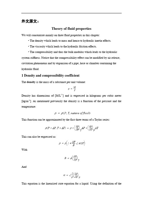
外文原文:Theory of fluid propertiesWe will concentrate mainly on three fluid properties in this chapter:• The density which leads to mass and hence to hydraulic inertia effects.• The viscosity which leads to the hydraulic friction effects.• The compressi bility and thus the bulk modulus which leads to the hydraulic system stiffness. Notice that the compressibility effect can be modified by air release, cavitation phenomena and by expansion of a pipe, hose or chamber containing the hydraulic fluid.1 Density and compressibility coefficientThe density is the mass of a substance per unit volume:Density has dimensions of [M/L3] and is expressed in kilograms per cubic meter [kg/m3]. As mentioned previously the density is a function of the pressure and the temperature:This function can be approximated by the first three terms of a Taylor series:This can also be expressed as:WithAndThis equation is the linearized state equation for a liquid. Using the definition of thedensity, the two coefficients α and B can also be expressed as:B is known as the isothermal bulk modulus or for simplicity the bulk modulus and α is known as the cubical expansion coefficient. Since fluid density varies with the applied pressure, this implies that a given mass of fluid submitted to a pressure change changes its volume. This phenomenon leads to the definition of the compressibility coefficient β:where β is expressed in units Pa 1 (or m2/N). Considering the relation for a closed hydraulic circuit the mass is constant, and hence:it follows thatUsing the definition of the compressibility coefficient β we obtain:More usually we use the bulk modulus B also known as the volumetric elasticity modulus:The relation between ρ and B implies mass conservation. This relation must be RIGOROUSLY RESPECTED in the calculations. In the modeling and simulation context of fluid energy systems, disregarding the relation between ρ and B leads to abnormal evolutions of pressure in the closed circuit submitted to compression and expansion cycles. This phenomenon is strongly accentuated if aeration occurs in the circuit (when dissolved air in the fluid reappears in the form of bubbles). We shall approach this point by examining the phenomena of aeration and cavitation. The aircan also have adverse consequences on a fluid compressibility. In liquid air can be present in two forms: entrapped and dissolved.Entrapped airWhen the return pipe is not submersed in the tank the liquid jet can entrain some air bubbles in the tank. Another phenomenon that affects the quantity of air in liquid is the leakage.Figure 1: Liquid leakageFigure 2: Air is entrainedThis air stays in the liquid as cavities and can modify the fluid compressibility. In this context we talk about effective bulk modulus. Figure 3 shows the bulk modulus of a diesel fuel at 40 °C with 0, 0.01, 0.1, 1, 10% air. The plot is obtained using the system shown. The model of the diesel fuel properties is based on accurate ex-perimental measurements and are designed for use with injection system which are very fast acting. For this reason air is assumed to be entrained rather than dissolved.Figure 3Dissolved airAir can also be dissolved in a liquid. A certain amount of air molecule can be part of the liquid. In this case the dissolved air does not significantly change the fluid properties.2 Air release and cavitationAir can be dissolved or entrained in liquids and it is possible for air to change from one of these two forms to the other depending on the conditions to which the fluid is subjected.Suppose the fluid is in equilibrium with a certain percentage of dissolved gas (usually air: nitrogen and oxygen). Lowering the pressure above a critical value called the saturation pressure induces aeration. This is the process where the dissolved gas forms air bubbles in the liquid until all the dissolved gases or air are free.The exact point where all the dissolved gas has come out of solution is difficult to pin-point because it depends on the chemical composition and behavior of the gas. This is a non-symmetrical dynamic process: the growing process does not have the same dynamics as when air bubbles disappear. In consequence the total amount of bubbles created when the pressure drops may or may not be redissolved in the liquid when it rises again.If the pressure is dropped further and above another critical value called the vapor pres s ure, the fluid itself starts to vaporize. It corresponds to a liquid phase change. At some point only fluid vapor and gas exist. In liquid systems the term cavitation usually refers to the formation and collapse of cavities in the liquid even if cavities contain air or liquid vapor.To summarize with a sketch what we have introduced see above:Figure 4: Air release and cavitationThe development of a cavity is now recognized as being associated with a nucleation center such as microscopic gas particles, wear or wall asperities. When the liquid is subjected to a tensile stress, cavities do not form as a result of liquid rupture but are caused by the rapid growth of these nuclei.To understand this, think of beer (or champagne if you prefer) in a bottle, when it is closed you see no air bubbles and the liquid does not look fizzy. The pressure in the bottle is above the saturation pressure of the gas in the liquid. When you open the bottle suddenly bubbles appear and so the dissolved gas (molecules of gas held in the liquid) starts to appear as gas.In fact the liquid is gas saturated and the atmospheric pressure is less than the saturation pressure of the liquid. This phenomenon is clearly not cavitation but air release (aeration). Considering nuclei effects, bubbles form only at particular places in your glass: around the glass (due to small asperities) and round any particles present in the liquid. Theoretically, if your liquid was perfectly pure and the wall of the system perfectly regular, air release or cavitation would occur with great difficulty! The key point about cavitation is that it is a phase change: the liquid changes to vapor.A comparison can be made between cavitation and boiling. If we look at the phasediagram below:Figure 5: Cavitation and boilingBoiling is a phase change at constant pressure and variable temperature and cavitation is a phase change at constant temperature and variable pressure.In any system air release starts first and if the pressure decreases further, cavitation may occur. This means that, sometimes, people talk about cavitation when the real phenomenon is air release. Both phenomena can lead to destruction of the material or component.In both cases it is entrained gas that causes the troubles. When cavities encounter high pressure in the downstream circuit, these bubbles or cavities can be unstable and can collapse implosively. The pressure developed at collapse can be large enough to cause severe mechanical damage in the containing vessel. It is well-known that hydraulic pumps and pipework can be badly damaged by cavitaton and air release.In all classical hydraulic systems air release and cavitation must be avoided to prevent material destruction but sometimes it is required like for injection systems to prepare the spray formation.3 ViscosityViscosity is a measure of the resistance of the fluid to flow. This characteristic has both positive and negative effects on fluid power systems. A low viscosity leads to oil leaks in the dead zone formed between the mechanical parts in movement, and a high viscosity will lead to loss of pressure in hydraulic ducts.Viscosity is a characteristic of liquids and gases and is manifested in motion throughinternal damping. Viscosity results from an exchange of momentum by molecular diffusion between two layers of fluid with different velocities. In this sense, the viscosity is a fluid property and not a flow property.Figure 6: ViscosityFigure 6 shows the relation between shearing constraint and difference of flow velocity between two layers .The definition of viscosity was first given by Newton. Between two layers of distance dy, the exerted force between these two layers is given by:where U(y) is the velocity depending on the radial position y and dU/dy the velocity gradient. This proportionality expresses the notion of Newtonian fluid and allows the introduction of μ defined as the dynamic viscosity or the absolute viscosity.The dimension of μ is [ML1-T 1-] and the SI unit is kg/m/s or Pa s. The older unit is the Poise, P, which is 0.1 kg/m/s. However, this is very small and hence the milli Poise, mP, is the common unit which is 10-4 kg/m/s.The dynamic viscosity is the constant of proportionality between a stress and the intensity of shearing between two neighboring layers:However the absolute viscosity is not very often used in fundamental equations. For example the dynamics of the elementary volume between the two layers is expressedas:and thus using the shear stress calculation:In other formulas (e.g. Navier Stokes) the ratio between the absolute viscosity and the density occurs so often that a new parameter called the kinematic viscosity ν is introduced .of dimension [L2T 1-] and so the SI unit is the m2/s. The older unit of kinematic viscosity is the Stoke, St, which is 104-m2/s. However, even this is a very small unit and hence the centistoke cSt is the common unit with 1 cSt = 106-m2/s. This parameter is easily measured with viscometers.Note that the viscosity varies significantly with the fluid temperature.Figure 7: Viscosity against temperatureNormally in absence of air release and cavitation the variation with pressure is not great unless the pressure is very extreme.Figure 8: Variation with pressureViscosity influence on the flowAnother important aspect of the viscosity is its influence on the flow conditions of the fluid. We can distinguish two types of flow conditions:• Laminar flow for which the flow lines are parallel and shearing forces create a pressure drop.• Turbulent flow for which the fluid particles have a disordered, random movement leading to a loss of pressure.These two conditions can be distinguished using the Reynolds number which is defined as follows:WithU: average fluid velocityd: diameter of the duct (hydraulic diameter for others geometries)ρ: densityμ: dynamic viscosityν: kinematic viscosityThe transition between laminar to turbulent flow occurs at the critical Reynolds number. This is not well defined, there exists always a transition region. In a hydraulic line, the critical Reynolds number is generally between 1500 to 2000. For uneven geometries (thin-walled orifices), the critical Reynolds number can be lower than 100. For non-circular cross sections, the hydraulic diameter can be used to determine the Reynolds number. Hydraulic diameter is defined as follows:We now give one example:• Circular orifice of diameter:Flow through orificesOrifices (also called restrictions) can be fixed or variable and occur in huge numbers in fluid systems. Not surprisingly in Engineering courses a mathematical description is presented. This is usually based on Bernoulli’s equation and leads to the formwhere Cq is the flow coefficient. This is variously described as typically 0.7 or varying with orifice geometry and Reynolds number.The second alternative is obviously more correct. If we do take a constant value, we are forced to have the gradient of Q against infinity at the origin! This cannot be and if you try to implement it is a numerical disaster! Clearly the flow is laminar for sufficiently small pressure drops which means that Cq is certainly not constant. One solution is to perform detailed e xperiments and compute Cq against Reynold’s number. In the context of the orifice (not necessarily circular) the Reynold’s number iswhere U is a mean velocity and dh the hydraulic diameter. If we take U=Q/A, we end up with the form Cq =f(Q) and ultimately withIt is possible to work with an implicit relationship like this but we would prefer an explicit formula.This is provided by introducing another dimensionless number known as the flow number and denoted by λ. This is defined asFrom a modelin g point of view λ contains quantities we know. Using λ we haveand provided we have,we have an explicit relationship which is easy to evaluate. There are no more problems to obtain measurements forthan forand so the flow number form has many advantages.References :[1] McCloy D, Discharge Characteristics of Servo Valve Orifices, 1968 Fluid International Conference.[2] R.C. Binder, “Fluid Mechanics”. 3rd Edition, 3rd Printing. Prentice-Hall, Inc., Englewood Cliffs,NJ. 1956.译文:液压油理论我们将在本章主要讨论液压油的三个特性:•密度(使油液具有质量和液感效应);•粘性(使油液具有液阻效应);•可压缩性和体积弹性模量(使油液具有容性效应),值得提醒的是容性效应会受油液中析出的空气、气穴现象和装有油液的的管道、软管或油腔的影响。
机械专业外文翻译-挖掘机的机械学和液压学
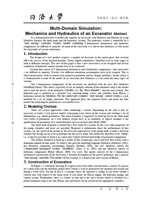
┊┊┊┊┊┊┊┊┊┊┊┊┊装┊┊┊┊┊订┊┊┊┊┊线┊┊┊┊┊┊┊┊┊┊┊┊┊Multi-Domain Simulation:Mechanics and Hydraulics of an Excavator Abstract It is demonstrated how to model and simulate an excavator with Modelica and Dymola by using Modelica libraries for multi-body and for hydraulic systems. The hydraulic system is controlled by a “load sensing” controller. Usually, models containing3-dimensional mechanical and hydraulic components are difficult to simulate. At hand of the excavator it is shown that Modelica is well suited for such kinds of system simulations.1. IntroductionThe design of a new product requires a number of decisions in the initial phase that severely affect the success of the finished machine. Today, digital simulation is therefore used in early stages to look at different concepts. The view of this paper is that a new excavator is to be designed and several candidates of hydraulic control systems have to be evaluated.Systems that consist of 3-dimensional mechanical and of hydraulic components – like excavators – are difficult to simulate. Usually, two different simulation environments have to be coupled. This is often inconvenient, leads to unnecessary numerical problems and has fragile interfaces. In this article it is demonstrated at hand of the model of an excavator that Modelica is well suited for these types of systems.The 3-dimensional components of the excavator are modeled with the new, free Modelica MultiBody library. This allows especially to use an analytic solution of the kinematic loop at the bucket and to take the masses of the hydraulic cylinders, i.e., the “force elements”, directly into account. The hydraulic part is modeled in a detailed way, utilizing pump, valves and cylinders from HyLib, a hydraulics library for Modelica. For the control part a generic “load sensing” control system is used, modeled by a set of simple equations. This approach gives the required results and keeps the time needed for analyzing the problem on a reasonable level.2. Modeling ChoicesThere are several approaches when simulating a system. Depending on the task it may be necessary to build a very precise model, containing every detail of the system and needing a lot of information, e.g., model parameters. This kind of models is expensive to build up but on the other hand very useful if parameters of a well defined system have to be modified. A typical example is the optimization of parameters of a counterbalance valve in an excavator (Kraft 1996).The other kind of model is needed for a first study of a system. In this case some properties of the pump, cylinders and loads are specified. Required is information about the performance of that system, e.g., the speed of the pistons or the necessary input power at the pump shaft, to make a decision whether this design can be used in principle for the task at hand. This model has therefore to be “cheap”, i.e., it must be possible to build it in a short time without detailed knowledge of particular components.The authors intended to build up a model of the second type, run it and have first results with a minimum amount of time spent. To achieve this goal the modeling language Modelica (Modelica 2002), the Modelica simulation environment Dymola (Dymola 2003), the new Modelica library for 3-dimensional mechanical systems “MultiBody”(Otter et al. 2003) and the Modelica library of hydraulic components HyLib (Beater 2000) was used. The model consists of the 3-dimensional mechanical construction of the excavator, a detailed description of the power hydraulics and a generic “load sensing” controller. This model will be available as a demo in the next version of HyLib.3. Construction of ExcavatorsIn Figure 1 a schematic drawing of a typical excavator under consideration is shown. It consists of a chain track and the hydraulic propel drive which is used to manoeuvre the machine but usually not during a work cycle. On top of that is a carriage where the operator is sitting. It can rotate around a vertical axis with respect to the chain track. It also holds the Diesel engine, the hydraulic pumps and control system. Furthermore, there is a boom, an arm and at the end a bucket which is attached via a planar kinematic loop to the arm. Boom, arm and bucket can be rotated by the appropriate cylinders.┊┊┊┊┊┊┊┊┊┊┊┊┊装┊┊┊┊┊订┊┊┊┊┊线┊┊┊┊┊┊┊┊┊┊┊┊┊Figure 2 shows that the required pressures in the cylinders depend on the position. For the “stretched” situation the pressure in the boom cylinder is 60 % higher than in the retracted position. Not only the position but also the movements have to be taken into account. Figure 3 shows a situation where the arm hangs down. If the carriage does not rotate there is a pulling force required in the cylinder. When rotating –excavators can typically rotate with up to 12 revolutions per minute –the force in the arm cylinder changes its sign and now a pushing force is needed. This change is very significant because now the “active” chamber of the cylinder switches and that must be taken into account by the control system. Both figures demonstrate that a simulation model must take into account the couplings between the four degrees of freedom this excavator has. A simpler model that uses a constant load for each cylinder and the swivel drive leads to erroneous results4. Load Sensing SystemExcavators have typically one Diesel engine, two hydraulic motors and three cylinders. There exist different hydraulic circuits to provide the consumers with the required hydraulic energy. A typical design is a Load Sensing circuit that is energy efficient and user friendly. The idea is to have a flow rate control system for the pump such that it delivers exactly the needed flow rate. As a sensor the pressure drop across an orifice is used. The reference value is the resistance of the orifice. A schematic drawing is shown in figure 4, a good introduction to that topic is given in (anon. 1992).The pump control valve maintains a pressure at the pump port that is typically 15 bar higher than the pressure in the LS line (= Load Sensing line). If the directional valve is closed the pump has therefore a stand-by pressure of 15 bar. If it is open the pump delivers a flow rate that leads to a pressure drop of 15 bar across that directional valve. Note: The directional valve is not used to throttle the pump flow but as a flow meter (pressure drop that is fed back) and as a reference (resistance). The circuit is energy efficient because the pump delivers only the needed flow rate, the throttling losses are small compared to other circuits.If more than one cylinder is used the circuit becomes more complicated, see figure 5. E.g. if the boom requires a pressure of 100 bar and the bucket a pressure of 300 bar the pump pressure must be above 300 bar which would cause an unwanted movement of the boom cylinder. Therefore compensators are used that throttle the oil flow and thus achieve a pressure drop of 15 bar across the particular directional valve. These compensators can be installed upstream or downstream of the directional valves. An additional valve reduces the nominal pressure differential if the maximum pump flow rate or the maximum pressure is reached (see e.g. Nikolaus 1994).5. Model of Mechanical PartIn Figure 6, a Modelica schematic of the mechanical part is shown. The chain track is not modeled, i.e., it is assumed that the chain track does not move. Components “rev1”, ..., “rev4” are the 4 revolute joints to move the parts relative to each other. The icons with the long black line are “virtual”rods that are used to mark specific points on a part, especially the mounting points of the hydraulic cylinders. The light blue spheres (b2, b3, b4, b5) are bodies that have mass and an inertia tensor and are used to model the corresponding properties of the excavator parts.The three components “cyl1f”, “cyl2f”,and “cyl3f” are line force components that describe a force interaction along a line between two attachment points. The small green squares at these components represent 1-dimensional translational connectors from theModelica.Mechanics. Translational library. They are used to define the 1- dimensional force law acting between the two attachment points. Here, the hydraulic cylinders described in the next section are directly attached. The small two spheres in the icons of the “cyl1f,cyl2f, cyl3f” components indicate that optionally two point masses are taken into account that are attached at defined distances from the attachment points along the connecting line. This allows to easily model the essential mass properties (mass and center of mass) of the hydraulic cylinders with only a very small computational overhead.The jointRRR component (see right part of Figure 6) is an assembly element consisting of 3 revolute joints that form together a planar loop when connected to the arm. A picture of this part of an excavator, a zoom in the corresponding Modelica schematic and the animation view is shown in Figure 7. When moving revolute joint “rev4” (= the large red cylinder in the lower part of Figure 7; the small┊┊┊┊┊┊┊┊┊┊┊┊┊装┊┊┊┊┊订┊┊┊┊┊线┊┊┊┊┊┊┊┊┊┊┊┊┊red cylinders characterize the 3 revolute joints of the jointRRR assembly component) the position and orientation of the attachment points of the “left”and “right” revolute joints of the jointRRR component are known. There is a non-linear algebraic loop in the jointRRR component to compute the angles of its three revolute joints given the movement of these attachment points. This non-linear system of equations is solved analytically in the jointRRR object, i.e., in a robust and efficient way. For details see In a first step, the mechanical part of the excavator is simulated without the hydraulic system to test this part separatly. This is performed by attaching translational springs with appropriate spring constants instead of the hydraulic cylinders. After the animation looks fine and the forces and torques in the joints have the expected size, the springs are replaced by the hydraulic system described in the next sections.All components of the new MultiBody library have “built-in” animation definitions, i.e., animation properties are mostly deduced by default from the given definition of the multi-body system. For example, a rod connecting two revolute joints is by default visualized as cylinder where the diameter d is a fraction of the cylinder length L (d = L/40) which is in turn given by the distance of the two revolute joints. A revolute joint is by default visualized by a red cylinder directed along the axis of rotation of the joint. The default animation (with only a few minor adaptations) of the excavator is shown if Figure 8. The light blue spheres characterize the center of mass of bodies. The line force elements that visualize the hydraulic cylinders are defined by two cylinders (yellow and grey color) that are moving in each other. As can be seen, the default animation is useful to get, without extra work from the user side, a rough picture of the model that allows to check the most important properties visually, e.g., whether the center of masses or attachment points are at the expected places.For every component the default animation can be switched off via a Boolean flag. Removing appropriate default animations, such as the “centerof- mass s pheres”, and adding some components that have pure visual information (all visXXX components in the schematic of Figure 6) gives quickly a nicer animation, as is demonstrated in Figure 9. Also CAD data could be utilized for the animation, but this was not available for the examination of this excavator.6. The Hydraulics Library HyLibThe (commercial) Modelica library HyLib (Beater 2000, HyLib 2003) is used to model the pump, metering orifice, load compensator and cylinder of the hydraulic circuit. All these components are standard components for hydraulic circuits and can be obtained from many manufacturers. Models of all of them are contained in HyLib. These mathematical models include both standard textbook models (e. g. Dransfield 1981, Merrit 1967, Viersma 1980) and the most advanced published models that take the behavior of real components into account (Schulz 1979, Will 1968). An example is the general pump model where the output flow is reduced if pressure at the inlet port falls below atmospheric pressure. Numerical properties were also considered when selecting a model (Beater 1999). One point worth mentioning is the fact that all models can be viewed at source code level and are documented by approx. 100 references from easily available literature.After opening the library, the main window is displayed (Figure 10). A double click on the “pumps” icon opens the selection for all components that are needed to originate or end an oil flow (Figure 11). For the problem at hand, a hydraulic flow source with internal leakage and externally commanded flow rate is used. Similarly the needed models for the valves, cylinders and other components are chosen.All components are modeled hierarchically. Starting with a definition of a connector –a port were the oil enters or leaves the component – a template for components with two ports is written. This can be inherited for ideal models, e.g., a laminar resistance or a pressure relief valve. While it usually makes sense to use textual input for these basic models most of the main library models were programmed graphically, i.e., composed from basic library models using the graphical user interface. Figure12 gives an example of graphical programming. All mentioned components were chosen from the library and then graphically connected.7. Library Components in Hydraulics CircuitThe composition diagram in Figure 12 shows the graphically composed hydraulics part of the excavator model. The sub models are chosen from the appropriate libraries, connected and the┊┊┊┊┊┊┊┊┊┊┊┊┊装┊┊┊┊┊订┊┊┊┊┊线┊┊┊┊┊┊┊┊┊┊┊┊┊parameters input. Note that the cylinders and the motor from HyLib can be simply connected to the also shown components of the MultiBody library. The input signals, i.e., the reference signals of the driver of the excavator, are given by tables, specifying the diameter of the metering orifice, i.e. the reference value for the flow rate. From the mechanical part of the excavator only the components are shown in Figure 12 that are directly coupled with hydraulic elements, such as line force elements to which the hydraulic cylinders are attached.8. Model of LS ControlFor this study the following approach is chosen: Model the mechanics of the excavator, the cylinders and to a certain extent the pump and metering valves in detail because only the parameters of the components will be changed, the general structure is fixed. This means that the diameter of the bucket cylinder may be changed but there will be exactly one cylinder working as shown in Figure 1. That is different for the rest of the hydraulic system. In this paper a Load Sensing system, or LS system for short, using one pump is shown but there are other concepts that have to be evaluated during an initial design phase. For instance the use of two pumps, or a separate pump for the swing.The hydraulic control system can be set up using meshed control loops. As there is (almost) no way to implement phase shifting behavior in purely hydraulic control systems the following generic LS system uses only proportional controllers.A detailed model based on actual components would be much bigger and is usually not available at the begin of an initial design phase. It could be built with the components from the hydraulics library but would require a considerable amount of time that is usually not available at the beginning of a project.In Tables 1 and 2, the implementation of the LS control in form of equations is shown. Usually, it is recommended for Modelica models to either use graphical model decomposition or to define the model by equations, but not to mix both descrip- tion forms on the same model level.For the LS system this is different because it has 17 input signals and 5 output signals. One might built one block with 17 inputs and 5 outputs and connect them to the hydraulic circuit. However, in this case it seems more understandable to provide the equations directly on the same level as the hydraulic circuit above and access the input and output signals directly. For example, ”metOri1.port_A.p” used in table 2 is the measured pressure at port_A of the metering orifice metOri1. The calculated values of the LS controller, e.g., the pump flow rate “pump.inPort.signal[1] = ...” is the signal at the filled blue rectangle of the “pump” component, see Figure 12).The strong point of Modelica is that a seamless integration of the 3-dimensional mechanical library, the hydraulics library and the non standard, and therefore in no library available, model of the control system is easily done. The library components can be graphically connected in the object diagram and the text based model can access all needed variables.9. Some Simulation ResultsThe complete model was built using the Modelica modeling and simulation environment Dymola (Dymola 2003), translated, compiled and simulated for 5 s. The simulation time was 17 s using the DASSL integrator with a relative tolerance of 10-6 on a 1.8 GHz notebook, i.e., about 3.4 times slower as real-time. The animation feature in Dymola makes it possible to view the movements in an almost realistic way which helps to explain the results also to non-experts, see Figure 9.Figure 13 gives the reference signals for the three cylinders and the swing, the pump flow rate and pressure. From t = 1.1 s until 1.7 s and from t = 3.6 s until 4.0 s the pump delivers the maximum flow rate. From t = 3.1 s until 3.6 s the maximum allowed pressure is reached. Figure 14 gives the position of the boom and the bucket cylinders and the swing angle. It can be seen that there is no significant change in the piston movement if another movement starts or ends. The control system reduces the couplings between the consumers which are very severe for simple throttling control.Figure 15 shows the operation of the bucket cylinder. The top figure shows the reference trajectory, i. e. the opening of the directional valve. The middle figure shows the conductance of the compensators. With the exception of two spikes it is open from t = 0 s until t = 1 s. This means that in┊┊┊┊┊┊┊┊┊┊┊┊┊装┊┊┊┊┊订┊┊┊┊┊线┊┊┊┊┊┊┊┊┊┊┊┊┊that interval the pump pressure is commanded by that bucket cylinder. After t = 1 s the boom cylinder requires a considerably higher pressure and the bucket compensator therefore increases the resistance (smaller conductance). The bottom figure shows that the flow rate control works fine. Even though there is a severe disturbance (high pump pressure after t = 1 s due to the boom) the commanded flow rate is fed with a small error to the bucket cylinder.10. ConclusionFor the evaluation of different hydraulic circuits a dynamic model of an excavator was built. It consists of a detailed model of the 3 dimensional mechanics of the carriage, including boom, arm and bucket and the standard hydraulic components like pump or cylinder. The control system was not modeled on a component basis but the system was described by a set of nonlinear equations.The system was modeled using the Modelica MultiBody library, the hydraulics library Hylib and a set of application specific equations. With the tool Dymola the system could be build and tested in a short time and it was possible to calculate the required trajectories for evaluation of the control system.The animation feature in Dymola makes it possible to view the movements in an almost realistic way which helps to explain the results also to多畴模拟:挖掘机的机械学和液压学概要:通过使用用于多体和液压系统的Modelica程序库,示范通过Modelica和Dymola如何模拟和仿真挖掘机。
液压系统外文文献翻译中英文

外文文献翻译(含:英文原文及中文译文)英文原文Hydraulic systemW Arnold1 IntroductionThe hydraulic station is called a hydraulic pump station and is an independent hydraulic device. It is step by step to supply oil. And control the direction of hydraulic oil flow, pressure and flow, suitable for the host and hydraulic equipment can be separated on the various hydraulic machinery.After the purchase, the user only needs to connect the hydraulic station and the actuator (hydraulic or oil motor) on the mainframe with different tubings. The hydraulic machine can realize various specified actions and working cycles.The hydraulic station is a combination of manifolds, pump units or valve assemblies, electrical boxes, and tank electrical boxes. Each part function is:The pump unit is equipped with a motor and an oil pump, which is the power source of the hydraulic station and can convert mechanical energy into hydraulic oil pressure energy.V alve combination - its plate valve is mounted on the vertical plate, and the rear plate is connected with the same function as the manifold.Oil manifolds - assembled from hydraulic valves and channel bodies. It regulates hydraulic oil pressure, direction and flow.Box--a semi-closed container for plate welding. It is also equipped with an oil screen, an air filter, etc., which is used for cooling and filtering of oil and oil.Electrical box - divided into two types: one is to set the external lead terminal board; one is equipped with a full set of control appliances.The working principle of the hydraulic station: The motor drives the oil pump to rotate, then the pump sucks oil from the oil tank and supplies oil, converts the mechanical energy into hydraulic pressure energy, and the hydraulic oil passes through the manifold (or valve assembly) to adjust the direction, pressure and flow and then passes through the external tube. The way to the hydraulic cylinder or oil motor in the hydraulic machinery, so as to control the direction of the hydraulic motor, the strength of the speed and speed, to promote all kinds of hydraulic machinery to do work.(1) Development history of hydraulic pressureThe development history of hydraulics (including hydraulic power, the same below), pneumatics, and seals industry in China can be roughly divided into three stages, namely: the starting stage in the early 1950s to the early 60s; and the professional in the 60s and 70s. The growth stage of the production system; the 80-90's is a stage of rapid development. Among them, the hydraulic industry began in the early 1950s with thedevelopment of hydraulic machines such as Grinding Machines, broaching machines, and profiling lathes, which were produced by the machine tool industry. The hydraulic components were produced by the hydraulic workshop in the machine tool factory, and were produced for self use. After entering the 1960s, the application of hydraulic technology was gradually promoted from the machine tool to the agricultural machinery and engineering machinery. The original hydraulic workshop attached to the main engine plant was independent and became a professional manufacturer of hydraulic components. In the late 1960s and early 1970s, with the continuous development of mechanization of production, particularly in the provision of highly efficient and automated equipment for the second automobile manufacturing plant, the hydraulic component manufacturing industry witnessed rapid development. The batch of small and medium-sized enterprises also began to become specialized manufacturers of hydraulic parts. In 1968, the annual output of hydraulic components in China was close to 200,000 pieces. In 1973, in the fields of machine tools, agricultural machinery, construction machinery and other industries, the professional factory for the production of hydraulic parts has grown to over 100, and its annual output exceeds 1 million pieces. Such an independent hydraulic component manufacturing industry has taken shape. At this time, the hydraulic product has evolved from the original imitation Su product intoa combination of imported technology and self-designed products. The pressure has been developed towards medium and high pressures, and electro-hydraulic servo valves and systems have been developed. The application of hydraulics has been further expanded. The pneumatic industry started a few years later than hydraulics, and it was only in 1967 that it began to establish a professional pneumatic components factory. Pneumatic components began to be manufactured and sold as commodities. Its sealing industry including rubber seals, flexible graphite seals, and mechanical seals started from the production of common O-rings, oil seals, and other extruded rubber seals and asbestos seal products in the early 1950s. In the early 1960s, it began to develop and produce flexible products. Graphite seals and mechanical seals and other products. In the 1970s, a batch of batches of professional production plants began to be established one after another in the systems of the former Ministry of Combustion, the Ministry of Agriculture, and the Ministry of Agricultural Machinery, formally forming the industry, which laid the foundation for the development of the seal industry.In the 1980s, under the guidance of the national policy of reform and opening up, with the continuous development of the machinery industry, the contradiction between the basic components lags behind the host computer has become increasingly prominent and caused the attention of all relevant departments. To this end, the former Ministry of Machinesestablished the General Infrastructure Industry Bureau in 1982, and unified the original pneumatic, hydraulic, and seal specialties that were scattered in the industries of machine tools, agricultural machinery, and construction machinery, etc. The management of a piece of office, so that the industry in the planning, investment, the introduction of technology and scientific research and development and other aspects of the basic parts of the bureau's guidance and support. This has entered a period of rapid development, it has introduced more than 60 foreign advanced technology, of which more than 40 hydraulic, pneumatic 7, after digestion and absorption and technological transformation, are now mass production, and has become the industry's leading products . In recent years, the industry has intensified its technological transformation. From 1991 to 1998, the total investment of national, local, and corporate self-raised funds totaled about 2 billion yuan, of which more than 1.6 billion were hydraulic. After continuous technological transformation and technological breakthroughs, the technical level of a group of major enterprises has been further improved, and technological equipment has also been greatly improved, laying a good foundation for forming a high starting point, specialization, and mass production. In recent years, under the guidance of the principle of common development of multiple ownership systems in the country, various small and medium-sized enterprises with different ownership have rapidly emerged and haveshown great vitality. With the further opening up of the country, foreign-funded enterprises have developed rapidly, which plays an important role in raising industry standards and expanding exports. So far China has established joint ventures with famous manufacturers in the United States, Germany, Japan and other countries or directly established piston pumps/motors, planetary speed reducers, hydraulic control valves, steering gears, hydraulic systems, hydrostatic transmissions, and hydraulic components. The company has more than 50 manufacturing enterprises such as castings, pneumatic control valves, cylinders, gas processing triplets, rubber seals, and mechanical seals, and has attracted more than 200 million U.S. dollars in foreign capital.(2) Current statusBasic profileAfter more than 40 years of hard work, China's hydraulics, pneumatics and seals industry has formed a complete industrial system with a certain level of production capacity and technical level. According to the statistics of the third n ational industrial census in 1995, China’s state-owned, privately-owned, cooperative, village-run, individual, and “funded enterprises” have annual sales income of more than 1 million yuan in hydraulic, pneumatic, and seal industrial townships and above. There are a total of more than 1,300 companies, including about 700 hydraulics, and about 300 pneumatic and sealing parts. According to thestatistics of the international industry in 1996, the total output value of the hydraulic industry in China was about 2.448 billion yuan, accounting for the 6th in the world; the total output value of the pneumatic industry was about 419 million yuan, accounting for the world’s10 people.2. Current supply and demand profileWith the introduction of technology, independent development and technological transformation, the technical level of the first batch of high-pressure plunger pumps, vane pumps, gear pumps, general hydraulic valves, oil cylinders, oil-free pneumatic components and various types of seals has become remarkable. Improve, and can be stable mass production, provide guarantees for all types of host to improve product quality. In addition, certain achievements have also been made in the aspects of CAD, pollution control, and proportional servo technology for hydraulic pneumatic components and systems, and have been used for production. So far, the hydraulic, pneumatic and seal products have a total of about 3,000 varieties and more than 23,000 specifications. Among them, there are about 1,200 types of hydraulic pressure, more than 10,000 specifications (including 60 types of hydrodynamic products, 500 specifications); about 1350 types of pneumatic, more than 8,000 specifications; there are also 350 types of rubber seals, more than 5000 The specifications are now basically able to adapt to the general needs ofvarious types of mainframe products. The matching rate for major equipment sets can reach more than 60%, and a small amount of exports has started.In 1998, the domestic production of hydraulic components was 4.8 million pieces, with sales of about 2.8 billion yuan (of which mechanical systems accounted for 70%); output of pneumatic components was 3.6 million pieces, and sales were about 550 million yuan (including mechanical systems accounting for about 60%) The production of seals is about 800 million pieces, and the sales volume is about 1 billion yuan (including about 50% of mechanical systems). According to the statistics of the annual report of the China Hydraulic and Pneumatic Sealing Industry Association in 1998, the production and sales rate of hydraulic products was 97.5% (101% of hydraulic power), 95.9% of air pressure, and 98.7% of seal. This fully reflects the basic convergence of production and sales.Although China's hydraulic, pneumatic and sealing industries have made great progress, there are still many gaps compared with the development needs of the mainframe and the world's advanced level, which are mainly reflected in the variety, performance and reliability of products. . Take hydraulic products as an example, the product varieties are only 1/3 of the foreign country, and the life expectancy is 1/2 of that of foreign countries. In order to meet the needs of key hosts, imported hosts, and majortechnical equipment, China has a large number of imported hydraulic, pneumatic, and sealing products every year. According to customs statistics and relevant data analysis, in 1998, the import volume of hydraulic, pneumatic and seal products was about 200 million U.S. dollars, of which the hydraulic pressure was about 140 million U.S. dollars, the pneumatics were 30 million U.S. dollars, and the seal was about 0.3 billion U.S. dollars. The year is slightly lower. In terms of amount, the current domestic market share of imported products is about 30%. In 1998, the total demand for hydraulic parts in the domestic market was about 6 million pieces, and the total sales volume was 4 billion yuan; the total demand for pneumatic parts was about 5 million pieces, and the total sales volume was over 700 million yuan; the total demand for seals was about 1.1 billion yuan. Pieces, total sales of about 1.3 billion yuan. (3) Future developments1. The main factors affecting development(1) The company's product development capability is not strong, and the level and speed of technology development can not fully meet the current needs for advanced mainframe products, major technical equipment and imported equipment and maintenance;(2) Many companies have lagged behind in manufacturing process, equipment level and management level, and their sense of quality is not strong, resulting in low level of product performance, unstable quality,poor reliability, and insufficiency of service, and lack of user satisfaction. And trusted branded products;(3) The degree of professional specialization in the industry is low, the power is scattered, the duplication of the low level is serious, the product convergence between the region and the enterprise leads to blind competition, and the prices are reduced each other, thus the efficiency of the enterprise is reduced, the funds are lacking, and the turnover is difficult. Insufficient investment in development and technological transformation has severely restricted the overall level of the industry and its competitive strength.(4) When the degree of internationalization of the domestic market is increasing, foreign companies have gradually entered the Chinese market to participate in competition, coupled with the rise of domestic private, cooperative, foreign-funded, and individual enterprises, resulting in increasing impact on state-owned enterprises. .2. Development trendWith the continuous deepening of the socialist market economy, the relationship between supply and demand in the hydraulic, pneumatic and sealed products has undergone major changes. The seller market characterized by “shortage” has basically become a buyer’s market characterized by “structured surplus”. Replaced by. From the perspective of overall capacity, it is already in a trend of oversupply, and in particular,general low-grade hydraulic, pneumatic and seals are generally oversupply; and like high-tech products with high technological content and high value and high value-added products that are urgently needed by the host, Can not meet the needs of the market, can only rely on imports. After China's entry into the WTO, its impact may be greater. Therefore, during the “10th Five-Y ear Plan” period, the growth of the industry’s output value must not only rely on the growth of quantity. Instead, it should focus on the structural contradiction of the industry and intensify efforts to adjust the industrial structure and product structure. It should be based on the improvement of quality. Product technology upgrades in order to adapt to and stimulate market demand, and seek greater development.2. Hydraulic application on power slide(1) Introduction of Power Sliding TableUsing the binding force curve diagram and the state space analysis method to analyze and study the sliding effect and the smoothness of the sliding table of the combined machine tool, the dynamics of the hydraulic drive system of the sliding table—the self-regulating back pressure regulating system are established. mathematical model. Through the digital simulation system of the computer, the causes and main influencing factors of the slide impact and the motion instability are analyzed. What kind of conclusions can be drawn from those, if we canreasonably design the structural dimensions of hydraulic cylinders and self-regulating back pressure regulators ——The symbols used in the text are as follows:s 1 - flow source, that is, the flow rate of the governor valve outlet;S el —— sliding friction of the sliding table;R - the equivalent viscous friction coefficient of the slide;I 1 - quality of slides and cylinders;12 - self-adjusting back pressure valve core quality;C 1, c 2 - liquid volume without cylinder chamber and rod chamber;C 2 - Self-adjusting back pressure valve spring compliance;R 1, R2 - Self-adjusting back pressure valve damping orifice fluid resistance;R 9 - Self-adjusting back pressure valve valve fluid resistance;S e2——initial pre-tightening force of self-adjusting back pressure valve spring;I 4, I5 - Equivalent liquid sense of the pipeline;C 5, C 6 - equivalent liquid capacity of the pipeline;R 5, R7 - Equivalent liquid resistance of the pipeline;V 3, V4 - cylinder rodless cavity and rod cavity volume;P 3, P4—pressure of the rodless cavity and rod cavity of the cylinder;F - the slide bears the load;V - speed of slide motion;In this paper, the power bond diagram and the state space splitting method are used to establish the system's motion mathematical model, and the dynamic characteristics of the slide table can be significantly improved.In the normal operation of the combined machine tool, the magnitude of the speed of the slide, its direction and the load changes it undergoes will affect its performance in varying degrees. Especially in the process of work-in-process, the unsteady movement caused by the advancing of the load on the slide table and the cyclical change of the load will affect the surface quality of the workpiece to be machined. In severe cases, the tool will break. According to the requirements of the Dalian Machine Tool Plant, the author used the binding force curve diagram and the state space analysis method to establish a dynamic mathematical model of a self-adjusting back pressure and speed adjustment system for the new hydraulic drive system of the combined machine tool slide. In order to improve the dynamic characteristics of the sliding table, it is necessary to analyze the causes and main influencing factors of the impetus and movement of the sliding table. However, it must pass the computer's digital simulation and the final results obtained from the research.(2) Dynamic Mathematical ModelThe working principle diagram of the self-adjusting back pressure speedregulation system of the combined machine tool slide hydraulic drive system is shown in the figure. This system is used to complete the work-cycle-stop-rewind. When the sliding table is working, the three-position four-way reversing valve is in the illustrated position. The oil supply pressure of the oil pump will remain approximately constant under the effective action of the overflow valve, and the oil flow passes through the reversing valve and adjusts the speed. The valve enters the rodless chamber of the cylinder to push the slide forward. At the same time, the pressurized oil discharged from the rod chamber of the cylinder will flow back to the tank through the self-regulating back pressure valve and the reversing valve. During this process, there was no change in the operating status of both the one-way valve and the relief valve. The complex and nonlinear system of the hydraulic drive system of the self-adjusting back pressure governor system is a kind of self-adjusting back-pressure governor system. To facilitate the study of its dynamic characteristics, a simple and reasonable dynamic mathematical model that only considers the main influencing factors is established. Especially important [1][2]. From the theoretical analysis and the experimental study, we can see that the system process time is much longer than the process time of the speed control valve. When the effective pressure bearing area of the rodless cavity of the fuel tank is large, the flow rate at the outlet of the speed control valve is instantaneous. The overshoot is reflected in thesmall change in speed of the slide motion [2]. In order to further broaden and deeply study the dynamic characteristics of the system so that the research work can be effectively performed on a miniature computer, this article will further simplify the original model [2], assuming that the speed control valve is output during the entire system pass. When the flow is constant, this is considered to be the source of the flow. The schematic diagram of the dynamic model structure of this system is shown in Fig. 2. It consists of a cylinder, a sliding table, a self-adjusting back pressure valve, and a connecting pipe.The power bond graph is a power flow graph. It is based on the transmission mode of the system energy, based on the actual structure, and uses the centralized parameters to represent the role of the subsystems abstractly as a resistive element R, a perceptual element I, and a capacitive element. Three kinds of role of C. Using this method, the physical concept of modeling is clear, and combined with the state-space analysis method, the linear system can be described and analyzed more accurately. This method is an effective method to study the dynamic characteristics of complex nonlinear systems in the time domain. According to the main characteristics of each component of the self-adjusting back pressure control system and the modeling rules [1], the power bond diagram of the system is obtained. The upper half of each key in the figure represents the power flow. The two variables that makeup the power are the force variables (oil pressure P and force F) and the flow variables (flow q and velocity v). The O node indicates that the system is connected in parallel, and the force variables on each key are equal and the sum of the flow variables is zero; 1 The nodes represent the series connection in the system, the flow variables on each key are equal and the sum of the force variables is Zero. TF denotes a transformer between different energy forms. The TF subscripted letter represents the conversion ratio of the flow variable or the force variable. The short bar on the key indicates the causal relationship between the two variables on the key. The full arrow indicates the control relationship. There are integral or differential relationships between the force and flow variables of the capacitive and perceptual elements in the three types of action elements. Therefore, a complex nonlinear equation of state with nine state variables can be derived from Fig. 3 . In this paper, the research on the dynamic characteristics of the sliding table starts from the two aspects of the slide's hedging and the smoothness of the motion. The fourth-order fixed-length Runge-Kutta is used for digital simulation on the IBM-PC microcomputer.(3) Slide advanceThe swaying phenomenon of the slide table is caused by the sudden disappearance of the load acting on the slide table (such as drilling work conditions). In this process, the table load F, the moving speed V, and thepressure in the two chambers of the cylinder P3 and P4 can be seen from the simulation results in Fig. 4. When the sliding table moves at a uniform speed under the load, the oil pressure in the rodless cavity of the oil cylinder is high, and a large amount of energy is accumulated in the oil. When the load suddenly disappears, the oil pressure of the cavity is rapidly reduced, and the oil is rapidly reduced. When the high-pressure state is transferred to the low-pressure state, a lot of energy is released to the system, resulting in a high-speed forward impact of the slide. However, the front slide of the sliding table causes the pressure in the rod cavity of the oil cylinder to cause the back pressure to rise, thereby consuming part of the energy in the system, which has a certain effect on the kicking of the slide table. We should see that in the studied system, the inlet pressure of the self-adjusting back pressure valve is subject to the comprehensive effect of the two-chamber oil pressure of the oil cylinder. When the load suddenly disappears, the pressure of the self-adjusting back pressure valve rapidly rises and stably exceeds the initial back pressure value. It can be seen from the figure that self-adjusting back pressure in the speed control system when the load disappears, the back pressure of the cylinder rises more than the traditional speed control system, so the oil in the rod cavity of the cylinder absorbs more energy, resulting in the amount of forward momentum of the slide It will be about 20% smaller than traditionalspeed control systems. It can be seen from this that the use of self-adjusting back-gear speed control system as a drive system slider has good characteristics in suppressing the forward punch, in which the self-adjusting back pressure valve plays a very large role.(4) The smoothness of the slideWhen the load acting on the slide changes periodically (such as in the case of milling), the speed of the slide will have to fluctuate. In order to ensure the processing quality requirements, it must reduce its speed fluctuation range as much as possible. From the perspective of the convenience of the discussion of the problem, assume that the load changes according to a sine wave law, and the resulting digital simulation results are shown in Figure 5. From this we can see that this system has the same variation rules and very close numerical values as the conventional speed control system. The reason is that when the change of the load is not large, the pressure in the two chambers of the fuel tank will not have a large change, which will eventually lead to the self-regulating back pressure valve not showing its effect clearly.(5) Improvement measuresThe results of the research show that the dynamic performance of a sliding table with self-regulating back pressure control system as a drive system is better than that of a traditional speed control system. To reduce the amount of kick in the slide, it is necessary to rapidly increase the backpressure of the rod cavity when the load disappears. To increase the smoothness of the sliding table, it is necessary to increase the rigidity of the system. The main measure is to reduce the volume of oil. From the system structure, it is known that the cylinder has a large volume between the rod cavity and the oil discharge pipe, as shown in Fig. 6a. Its existence in terms of delay and attenuation of the self-regulating back pressure valve function, on the other hand, also reduces the rigidity of the system, it will limit the further improvement of the propulsion characteristics and the smoothness of the motion. Thus, improving the dynamic characteristics of the sliding table can be handled by two methods: changing the cylinder volume or changing the size of the self-regulating back pressure valve. Through the simulation calculation of the structural parameters of the system and the comparison of the results, it can be concluded that the ratio of the volume V4 between the rod cavity and the oil discharge pipe to the volume V3 between the rodless cavity and the oil inlet pipe is changed from 5.5 to 5.5. At 1 oclock, as shown in the figure, the diameter of the bottom end of the self-adjusting back pressure valve is increased from the original 10mm to 13mm, and the length of the damper triangle groove is reduced from the original lmm to 0.7mm, which will enable the front of the slide table. The impulse is reduced by 30%, the transition time is obviously shortened, and the smoothness of the slide motion will also be greatly improved.中文译文液压系统W Arnold1. 绪论液压站称液压泵站,是独立的液压装置。
机械设计外文文献翻译、中英文翻译

机械设计外文文献翻译、中英文翻译unavailable。
The first step in the design process is to define the problem and XXX are defined。
the designer can begin toXXX evaluated。
and the best one is XXX。
XXX.Mechanical DesignA XXX machines include engines。
turbines。
vehicles。
hoists。
printing presses。
washing machines。
and XXX and methods of design that apply to XXXXXX。
cams。
valves。
vessels。
and mixers.Design ProcessThe design process begins with a real need。
Existing apparatus may require XXX。
efficiency。
weight。
speed。
or cost。
while new apparatus may be XXX。
To start。
the designer must define the problem and XXX。
ideas and concepts are generated。
evaluated。
and refined until the best one is XXX。
XXX.XXX。
assembly。
XXX.During the preliminary design stage。
it is important to allow design XXX if some ideas may seem impractical。
they can be corrected early on in the design process。
- 1、下载文档前请自行甄别文档内容的完整性,平台不提供额外的编辑、内容补充、找答案等附加服务。
- 2、"仅部分预览"的文档,不可在线预览部分如存在完整性等问题,可反馈申请退款(可完整预览的文档不适用该条件!)。
- 3、如文档侵犯您的权益,请联系客服反馈,我们会尽快为您处理(人工客服工作时间:9:00-18:30)。
Hydraulic machinery and pumpHydraulic machinery are machines and tools which use fluid power to do work. Heavy equipment is a common example.In this type of machine, high-pressure liquid - called hydraulic fluid - is transmitted throughout the machine to various hydraulic motors and hydraulic cylinders. The fluid is controlled directly or automatically by control valves and distributed through hoses and tubes.The popularity of hydraulic machinery is due to the very large amount of power that can be transferred through small tubes and flexible hoses, and the high power density and wide array of actuators that can make use of this power.Hydraulic machinery is operated by the use of hydraulics, where a liquid is the powering medium. Pneumatics, on the other side, is based on the use of a gas as the medium for power transmission, generation and control.Hydraulic circuitsFor the hydraulic fluid to do work, it must flow to the actuator and or motors, then return to a reservoir.The fluid is then filtered and re-pumped. The path taken by hydraulic fluid is called a hydraulic circuit of which there are several types. Open center circuits use pumps which supply acontinuous flow. The flow is returned to tank through the control valve's open center; that is, when the control valve is centered, it provides an open return path to tank and the fluid is not pumped to a high pressure. Otherwise, if the control valve is actuated it routes fluid to and from an actuator and tank. The fluid's pressure will rise to meet any resistance, since the pump has a constant output. If the pressure rises too high, fluid returns to tank through a pressure relief valve.Hydraulic pumps supply fluid to the components in the system. Pressure in the system develops in reaction to the load. Hence, a pump rated for 5,000 psi is capable of maintaining flow against a load of 5,000 psi.Pumps have a power density about ten times greater than an electric motor (by volume). They are powered by an electric motor or an engine, connected through gears, belts, or a flexible elastomeric coupling to reduce vibration.Common types of hydraulic pumps to hydraulic machinery applications are;Gear pump: cheap, durable, simple. Less efficient, because they are constant displacement, and mainly suitable for pressures below 20 MPa (3000 psi).Vane pump: cheap and simple, reliable (especially in g-rotor form). Good for higher-flow low-pressure output.Axial piston pump: many designed with a variable displacement mechanism, to vary output flow for automatic control of pressure. There are various axial piston pump designs, including swashplate and checkball. The most common is the swashplate pump.Radial piston pump: A pump that is normally used for very high pressure at small flows.Piston pumps are more expensive than gear or vane pumps, but provide longer life operating at higher pressure, with difficult fluids and longer continuous duty cycles. Piston pumps make up one half of a hydrostatic transmission.Control valvesDirectional control valves route the fluid to the desired actuator. They usually consist of a spool inside a cast iron or steel housing. Directional control valves are usually designed to be stackable, with one valve for each hydraulic cylinder, and one fluid input supplying all the valves in the stack.The spool position may be actuated by mechanical levers, hydraulic pilot pressure, or solenoids which push the spool left or right.The main valve block is usually a stack of off the shelf directional control valves chosen by flow capacity and performance. Some valves are designed to be proportional (flow rate proportional to valve position), while others may be simply on-off. The controlvalve is one of the most expensive and sensitive parts of a hydraulic circuit.Pressure relief valves are used in several places in hydraulic machinery; on the return circuit to maintain a small amount of pressure for brakes, pilot lines, etc... On hydraulic cylinders, to prevent overloading and hydraulic line rupture. On the hydraulic reservoir, to maintain a small positive pressure which excludes moisture and contamination.Pressure reducing valves reduce the supply pressure as needed for various circuits.Check valves are one-way valves, allowing an accumulator to charge and maintain its pressure after the machine is turned off, for example.Counterbalance valves are in fact a special type of pilot controlled check valve. Whereas the check valve is open or closed, the counterbalance valve acts a bit like a pilot controlled flow control. Hydraulic pump typesGear pumpsGear pumps (with external teeth) (fixed displacement) are simple and economical pumps. The swept volume or displacement of gearpumps for hydraulics will be between about 1 cm3 (0.001 litre) and 200 cm3(0.2 litre). These pumps create pressure through the meshing of the gear teeth, which forces fluid around the gears to pressurize the outlet side. Some gear pumps can be quite noisy, compared to other types, but modern gear pumps are highly reliable and much quieter than older models.Rotary vane pumpsRotary vane pumps(fixed and simple adjustable displacement) have higher efficiencies than gear pumps, but are also used for mid pressures up to 180 bars in general. Some types of vane pumps can change the centre of the vane body, so that a simple adjustable pump is obtained. These adjustable vane pumps are in general constant pressure or constant power pumps: the displacement is increased until the required pressure or power is reached and subsequently the displacement or swept volume is decreased until an equilibrium is reached.Screw pumpsScrew pumps (fixed displacement) are a double Archimedes' screw, but closed. This means that two screws are used in one body. The pumps are used for high flows and relatively low pressure (max 100 bar). They were used on board ships where the constant pressure hydraulic system was going through the whole ship,especially for the control of ball valves, but also for the steering gear and help drive systems. The advantage of the screw pumps is the low sound level of these pumps; the efficiency is not that high. Bent axis pumpsBent axis pumps, axial piston pumps and motors using the bent axis principle, fixed or adjustable displacement, exists in two different basic designs. The Thoma-principle (engineer Hans Thoma, Germany, patent 1935) with max 25 degrees angle and the Wahlmark-principle (Gunnar Axel Wahlmark, patent 1960) with spherical-shaped pistons in one piece with the piston rod, piston rings, and maximum 40 degrees between the driveshaft centerline and pistons (Volvo Hydraulics Co.). These have the best efficiency of all pumps. Although in general the largest displacements are approximately one litre per revolution, if necessary a two-liter swept volume pump can be built. Often variable-displacement pumps are used, so that the oil flow can be adjusted carefully. These pumps can in general work with a working pressure of up to 350–420 bars in continuous work.Axial piston pumps swashplate principleAxial piston pumps using the swashplate principle (fixed and adjustable displacement) have a quality that is almost the same as the bent axis model. They have the advantage of being morecompact in design. The pumps are easier and more economical to manufacture; the disadvantage is that they are more sensitive to oil contamination.Radial piston pumpsRadial piston pumps(fixed displacement) are used especially for high pressure and relatively small flows. Pressures of up to 650 bar are normal. In fact variable displacement is not possible, but sometimes the pump is designed in such a way that the plungers can be switched off one by one, so that a sort of variable displacement pump is obtained.Peristaltic pumpsPeristaltic pumps are not generally used for high pressures. Pumps for open and closed systemsMost pumps are working in open systems. The pump draws oil from a reservoir at atmospheric pressure. It is very important that there is no cavitation at the suction side of the pump. For this reason the connection of the suction side of the pump is larger in diameter than the connection of the pressure side. In case of the use of multi-pump assemblies, the suction connection of the pump is often combined. It is preferred to have free flow to the pump (pressure at inlet of pump at least 0.8 bars). The body of the pump is often in open connection with the suction side of the pump.In case of a closed system, both sides of the pump can be at high pressure. The reservoir is often pressurized with 6-20 bars boost pressure. For closed loop systems, normally axial piston pumps are used. Because both sides are pressurized, the body of the pump needs a separate leakage connection.Multi pump assemblyIn a hydraulic installation, one pump can serve more cylinders and motors. The problem however is that in that case a constant pressure system is required and the system always needs the full power. It is more economic to give each cylinder and motor its own pump. In that case multi pump assemblies can be used. Gearpumps can often be obtained as multi pumps. The different chambers (sometimes of different size) are mounted in one body or built together. Also vane pumps can often be obtained as a multi pump. Gerotor pumps are often supplied as multi pumps. Screw pumps can be built together with a gear pump or a vane pump. Axial piston swashplate pumps can be built together with a second pump of the same or smaller size, or can be built together with one or more gear pumps or vane pumps (depending on the supplier). Axial plunger pumps of the bent axis design can not be built together with other pumps.翻译液压机械及泵液压机械是机械和工具,它使用流体的力量去做的工作。