Orion Status Update-April2012
moxa 的e1212用法 -回复

moxa 的e1212用法-回复ReentrantLock(可重入锁)是Java中的一种同步工具,它提供了比synchronized关键字更为灵活的线程同步机制。
ReentrantLock内部维护了一个同步队列(AQS,AbstractQueuedSynchronizer),使用该队列中的节点(Node)来管理等待获取锁的线程。
在ReentrantLock的内部,还有一种重要的概念,即Condition(条件)。
Condition对象是由ReentrantLock创建的,它提供了一种线程间的协议,用于控制线程的等待(await)和唤醒(signal)操作。
本文将详细探讨ReentrantLock的Condition原理,并解释如何使用它来实现多线程之间的协作。
一、Condition的基本概念Condition接口提供了一种线程阻塞和唤醒的机制,以及一些与锁绑定的条件(condition),它与ReentrantLock紧密关联。
每个Condition对象都与一个ReentrantLock关联,并通过ReentrantLock进行创建。
与Object类中的wait和notify方法类似,Condition提供了await和signal 方法来实现线程的等待和唤醒操作。
Condition的主要方法包括:1. await():使当前线程进入等待状态,同时释放当前线程对应的锁,直到被其他线程调用signal或signalAll方法唤醒。
2. awaitUninterruptibly():与await方法相比,该方法不会响应中断,不会抛出InterruptedException异常。
3. signal():唤醒一个等待在该Condition上的线程,如果有多个线程在等待,则只唤醒其中一个。
4. signalAll():唤醒所有等待在该Condition上的线程。
二、Condition的底层实现在深入探究Condition的原理之前,我们先来了解ReentrantLock的底层实现。
nVent ERICO PlusCU 2L 6V 电源控制器操作指南说明书

C o u n t -u p I g n i t i o n I n d i c a t o rT r i g g e r G u a r dT r i g g e rB a t t e r y D o o rB a t t e r y I n d i c a t o rC a d w e l d P l u s C u p C o n n e c t o rP L U S C U 2L 6P L U S C U 2L 15P L U S C U 2L 6N B P B P L U S C U 2L 6P B P L U S C U 2L 15P L U S C U 2R L D 6P L U S C U 2R L D 15L e a d C o n n e c t o rIndicator lights are flashing:The PlusCU uses an internal charging mechanism that sends an electric current to the Cadweld Plus cup. If the trigger on the control unit is pulled before the internal charging mechanism resets, the lights will flash. Wait 5 seconds and try again.If the error message persists, contact your nVent ERICO representative.PlusCU does not respond when trigger is pulled:If the unit does not respond, check battery status to determine if new batteries are needed.Cadweld Plus cup does not ignite:Disconnect the PlusCU lead from the PlusCU then re-examine your mold, weldmetal cup, ignition strip, and other Cadweld equipment to verify proper setup.If this issue persists, contact your nVent ERICO representative.PlusCU does not function properly at temperatures below 0° F [-18°C]:Alkaline batteries are not intended for extreme cold temperatures. nVent ERICOrecommends the use of lithium-ion batteries at temperatures below 0° F [-18°C].WARNING:nVent products shall be installed and used only as indicated in nVent product instruction sheets and training materials. Instruction sheets are available at and from your nVent customer service representative. nVent products must never be used for a purpose other than the purpose for which they were designed or in a manner that exceeds specified load ratings.2.All instructions must be completely followed to ensure proper and safe installation and performance.3.Improper installation, misuse, misapplication or other failure to completely follow nVent's instructions and warnings may cause product malfunction, property4.damage, serious bodily injury and/or death, and void your warranty.SAFETY INSTRUCTIONS:All governing codes and regulations and those required by the job site must be observed.Always use appropriate safety equipment such as eye protection, hard hat, and gloves as appropriate to the application.nVent, nVent CADDY, nVent ERICO Cadweld, nVent ERICO Critec, nVent ERICO, nVent ERIFLEX, and nVent LENTON are owned byHigh voltage electrical shock hazard. Keep hands and body clear of the cord(leads) while operating. Failure to do so can result in death or serious injury.Safety First!Personal SafetyWhen working with nVent ERICO Cadweld Plus, always use appropriate safety equipment suchas eye protection, heat-resistant gloves, and other PPE as appropriate to the application and required by local safety codes.Avoid contact with hot materials. Maintain safe working distance and secure footing whilewelding or working with hot materials.Welding material is a mixture of oxides and metal which react to produce hot molten materialwith temperatures in excess of 1400° C [2500° F] and a localized release of smoke. Thesereactions are not explosive and not known to be toxic. Ignition temperatures of weldingmaterial are in excess of 900° C [1650° F] and will not ignite under ambient conditions.For reduced or eliminated smoke options, contact nVent ERICO.。
ORA-00603ORA-27504ORA-27300ORA-27301ORA-27302参考学习

ORA-00603ORA-27504ORA-27300ORA-27301ORA-27302参考学习--节点1 告警⽇志Thu Jun 20 03:02:18 2019Thread 1 advanced to log sequence 2092 (LGWR switch)Current log# 11 seq# 2092 mem# 0: +DATA/test/onlinelog/redo11_1.logCurrent log# 11 seq# 2092 mem# 1: +DATA/test/onlinelog/redo11_2.logThu Jun 20 03:02:18 2019LNS: Standby redo logfile selected for thread 1 sequence 2092 for destination LOG_ARCHIVE_DEST_2Thu Jun 20 03:02:20 2019Archived Log entry 5703 added for thread 1 sequence 2091 ID 0x9b8db1ed dest 1:Thu Jun 20 03:03:53 2019skgxpvfynet: mtype: 61 process 316751 failed because of a resource problem in the OS. The OS has most likely run out of buffers (rval: 4) Errors in file /u01/app/oracle/diag/rdbms/test/test1/trace/test1_ora_316751.trc (incident=560025):ORA-00603: ORACLE server session terminated by fatal errorORA-27504: IPC error creating OSD contextORA-27300: OS system dependent operation:sendmsg failed with status: 105ORA-27301: OS failure message: No buffer space availableORA-27302: failure occurred at: sskgxpsnd2Incident details in: /u01/app/oracle/diag/rdbms/test/test1/incident/incdir_560025/test1_ora_316751_i560025.trcThu Jun 20 03:03:54 2019Dumping diagnostic data in directory=[cdmp_20190620030354], requested by (instance=1, osid=316751), summary=[incident=560025]. opiodr aborting process unknown ospid (316751) as a result of ORA-603Thu Jun 20 03:04:03 2019Sweep [inc][560025]: completedSweep [inc2][560025]: completedThu Jun 20 03:06:15 2019Thread 1 advanced to log sequence 2093 (LGWR switch)Current log# 5 seq# 2093 mem# 0: +DATA/test/onlinelog/redo05_1.logCurrent log# 5 seq# 2093 mem# 1: +DATA/test/onlinelog/redo05_2.logThu Jun 20 03:06:16 2019---trc ⽂件--trc⽂件,初步看应该是服务器⽹卡mtu值相关问题*** 2019-06-20 03:03:53.395*** CLIENT ID:() 2019-06-20 03:03:53.395*** SERVICE NAME:() 2019-06-20 03:03:53.395*** MODULE NAME:() 2019-06-20 03:03:53.395*** ACTION NAME:() 2019-06-20 03:03:53.395SKGXP:[7f5ab0ef57c0.0]{0}: SKGXPVFYNET: Socket self-test could not verify successful transmission of 32768 bytes (mtype 61). SKGXP:[7f5ab0ef57c0.1]{0}: The network is required to support UDP protocol sends of this size. Socket is bound to 169.254.16.188. SKGXP:[7f5ab0ef57c0.2]{0}: phase 'send', 0 tries, 100 loops, 32354 ms (last)struct ksxpp * ksxppg_ [0xc11fde0, 0x7f5aadaf5588) = 0x7f5aadaf5580Dump of memory from 0x00007F5AADAF5580 to 0x00007F5AADAF6AB0---数据库状态select INST_ID,INSTANCE_NAME,STARTUP_TIME from gv$instance;--添加到CRTset lines 1000\r alter session set nls_date_format='yyyymmdd hh24:mi:ss';\r set time on \r selectINST_ID,INSTANCE_NAME,STARTUP_TIME from gv$instance;09:42:29 SYS@test1(test1)> set lines 100009:43:30 SYS@test1(test1)> alter session set nls_date_format='yyyymmdd hh24:mi:ss';Session altered.09:43:31 SYS@test1(test1)> set time on09:43:31 SYS@test1(test1)> select INST_ID,INSTANCE_NAME,STARTUP_TIME from gv$instance;INST_ID INSTANCE_NAME STARTUP_TIME---------- ---------------- -----------------1 test1 20190509 15:30:082 test2 20190507 21:37:04---节点2 ⽇志Thu Jun 20 03:03:54 2019Dumping diagnostic data in directory=[cdmp_20190620030354], requested by (instance=1, osid=316751), summary=[incident=560025]. Thu Jun 20 03:10:10 2019Thread 2 advanced to log sequence 912 (LGWR switch)Current log# 6 seq# 912 mem# 0: +DATA/test/onlinelog/redo06_1.logCurrent log# 6 seq# 912 mem# 1: +DATA/test/onlinelog/redo06_2.log---参考官⽅⽂档2041723.1CAUSEThis happens due to less space available for network buffer reservation.SOLUTION1. On servers with High Physical Memory, the parameter vm.min_free_kbytes should be set in the order of 0.4% of total Physical Memory. This helps in keeping a larger range of defragmented memory pages available for network buffers reducing the probability of a low-buffer-space conditions.*** For example, on a server which is having 256GB RAM, the parameter vm.min_free_kbytes should be set to 1073742 ***On NUMA Enabled Systems, the value of vm.min_free_kbytes should be multiplied by the number of NUMA nodes since the value is to be split across all the nodes.On NUMA Enabled Systems, the value of vm.min_free_kbytes = n * 0.4% of total Physical Memory. Here 'n' is the number of NUMA nodes.2. Additionally, the MTU value should be modified as below#ifconfig lo mtu 16436To make the change persistent over reboot add the following line in the file /etc/sysconfig/network-scripts/ifcfg-lo :MTU=16436Save the file and restart the network service to load the changes#service network restartNote : While making the changes in CRS nodes, if network is restarted while CRS is up, it can hung CRS. So cluster services should be stopped prior to the network restart.---实际操作,两个节点执⾏[root@test1 bin]# ifconfig lo mtu 16436[root@test1 bin]#[root@test1 bin]# vi /etc/sysconfig/network-scripts/ifcfg-loDEVICE=loIPADDR=127.0.0.1NETMASK=255.0.0.0NETWORK=127.0.0.0# If you're having problems with gated making 127.0.0.0/8 a martian,# you can change this to something else (255.255.255.255, for example)BROADCAST=127.255.255.255ONBOOT=yesNAME=loopbackMTU=16436---重启⽹络服务# systemctl stop network# systemctl start network⼆、设定 vm.min_free_kbytes 参数为物理内存的0.4%For example, on a server which is having 256GB RAM, the parameter vm.min_free_kbytes should be set to 1073742 *** ---此次修改主机内存 512G ,所以这个值是 1073742*2=2147484vm.min_free_kbytes=2147484[oracle@test1 ~]$ cat /proc/sys/vm/min_free_kbytes65536[oracle@test1 ~]$调整MIN_FREE_KBYTES的⽬的是保持物理内存有⾜够的空闲空间,防⽌突发性的换页。
飞泛(Futaba)Futaba14SG R7 firmware更新说明书
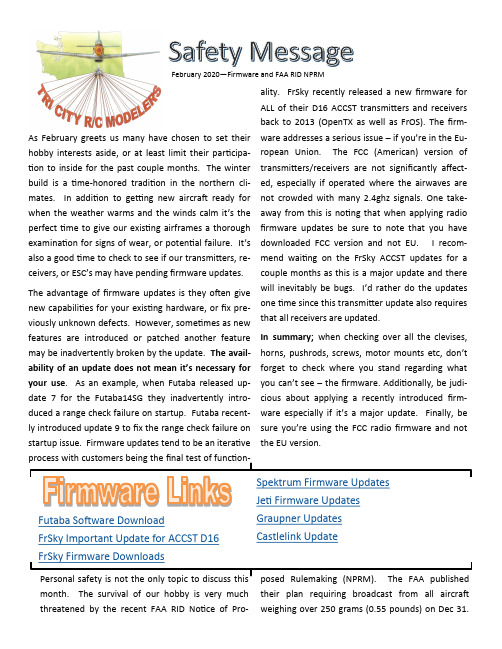
February 2020—Firmware and FAA RID NPRMAs February greets us many have chosen to set theirhobby interests aside, or at least limit their participa-tion to inside for the past couple months. The winterbuild is a time-honored tradition in the northern cli-mates. In addition to getting new aircraft ready forwhen the weather warms and the winds calm it’s theperfect time to give our existing airframes a thoroughexamination for signs of wear, or potential failure. It’salso a good time to check to see if our transmitters, re-ceivers, or ESC’s may have pending firmware updates.The advantage of firmware updates is they often givenew capabilities for your existing hardware, or fix pre-viously unknown defects. However, sometimes as newfeatures are introduced or patched another featuremay be inadvertently broken by the update. The avail-ability of an update does not mean it’s necessary foryour use. As an example, when Futaba released up-date 7 for the Futaba14SG they inadvertently intro-duced a range check failure on startup. Futaba recent-ly introduced update 9 to fix the range check failure onstartup issue. Firmware updates tend to be an iterativeprocess with customers being the final test of function-Futaba Software DownloadFrSky Important Update for ACCST D16 FrSky Firmware Downloads Spektrum Firmware Updates Jeti Firmware Updates Graupner Updates Castlelink UpdatePersonal safety is not the only topic to discuss this month. The survival of our hobby is very much threatened by the recent FAA RID Notice of Pro-posed Rulemaking (NPRM). The FAA published their plan requiring broadcast from all aircraft weighing over 250 grams (0.55 pounds) on Dec 31. ality. FrSky recently released a new firmware for ALL of their D16 ACCST transmitters and receivers back to 2013 (OpenTX as well as FrOS). The firm-ware addresses a serious issue –if you’re in the Eu-ropean Union. The FCC (American) version of transmitters/receivers are not significantly affect-ed, especially if operated where the airwaves are not crowded with many 2.4ghz signals. One take-away from this is noting that when applying radio firmware updates be sure to note that you have downloaded FCC version and not EU. I recom-mend waiting on the FrSky ACCST updates for a couple months as this is a major update and there will inevitably be bugs. I’d rather do the updates one time since this transmitter update also requires that all receivers are updated.In summary; when checking over all the clevises, horns, pushrods, screws, motor mounts etc, don’t forget to check where you stand regarding what you can’t see –the firmware. Additionally, be judi-cious about applying a recently introduced firm-ware especially if it’s a major update. Finally, be sure you’re using the FCC radio firmware and not the EU version.Don’t be misled by the term “drone” in the NPRM. The FAA uses the term “drone” to apply to all Un-manned Aircraft Systems(UAS), this includes every-thing we fly at TCRCM field and may even include free flight and control line. This NPRM is open for public comment until March 2. The AMA, and EAA (Experimental Aircraft Association) as well as others petitioned in vain for an extension to the comment period. In response to the request for an extention FAA replied on January 28:“…the need for remote identification of UAS increas-ingly has become important as new public safety and national security concerns arise regarding the use of UAS. Accordingly, the FAA has determined that any extension of the comment period, and the subse-quent delays in promulgation of a final rule imple-menting remote identification of UAS, would not be consistent with the safety and security objectives of the proposed rule.Therefore, your request to extend the comment pe-riod for the Remote Identification of Unmaimed Air-craft Systems NPRM is denied. The comment period for the NPRM closes on Monday, March 2, 2020.”Once one dives into the 319 page NPRM in depth it details how the FAA is proposing to progressively annihilate the hobby. This NPRM proposes to make it illegal for a land owner to fly over their own land in the short term, and eventually eliminate model flying fields for home-built aircraft like we now fly. There are many many levels of concern. Grouping Line of Sight (LOS) modeling in with the regulations of Beyond Visual Line of sight BVLOS operations is a one size fits all solution that is inappropriate. Making it impossible to establish new flying fields, or even move an existing club flying field to a new location is well beyond what Congress mandated in the FAA reauthorization act of 2018. To assist with digesting the information about the NRPM, Jim Andersan has posted a page of infor-mation on the Club Website. There are also links to two summaries of the NPRM in the sources below.It’s seriously imperative that all interested reach out to the FAA and to all elected representatives. Even if your position is that you have no intention of follow-ing these rules then politely tell the FAA that they can expect noncompliance from otherwise law abid-ing citizens.Some would say that contacting FAA or representa-tive will make no difference. If that’s the case we’re no worse off and you did what you could. Your com-ments MAY make a difference in which case it’s time and energy well spent.Links to Contacts:• Dan Newhouse• Patty Murray• Maria Cantwell• White House• FAA RID NPRM Comment pageLinks to Information and resources.• Layman’s Guide to the NPRM for Remote ID• AMA summary of the RID NPRM• AMA Templates to use to assist in drafting your own response.• Our club website。
os-e401_2012-04

OFFSHORE STANDARDDNV-OS-E401Helicopter DecksAPRIL 2012The electronic pdf version of this document found through is the officially binding versionD ET N ORSKE V ERITAS AS© Det Norske Veritas AS April 2012Any comments may be sent by e-mail to rules@This service document has been prepared based on available knowledge, technology and/or information at the time of issuance of this document, and is believed to reflect the best of contemporary technology. The use of this document by others than DNV is at the user's sole risk. DNV does not accept any liability or responsibility for loss or damages resulting from any use of this document.FOREWORDDET NORSKE VERITAS (DNV) is an autonomous and independent foundation with the objectives of safeguarding life,property and the environment, at sea and onshore. DNV undertakes classification, certification, and other verification and consultancy services relating to quality of ships, offshore units and installations, and onshore industries worldwide, and carries out research in relation to these functions.DNV service documents consist of among others the following types of documents:—Service Specifications. Procedural requirements.—Standards. Technical requirements.—Recommended Practices. Guidance.The Standards and Recommended Practices are offered within the following areas:A)Qualification, Quality and Safety Methodology B)Materials Technology C)Structures D)SystemsE)Special Facilities F)Pipelines and Risers G)Asset Operation H)Marine Operations J)Cleaner Energy O)Subsea SystemsCHANGESGeneralThis document supersedes DNV-OS-E401, April 2011.Text affected by the main changes in this edition is highlighted in red colour. However, if the changes involve a whole chapter, section or sub-section, normally only the title will be in red colour.Main changes—Ch.1 Sec.1 new text A202 regarding scope of this standard.—Ch.1 Sec.1 Table B1 new reference.—Ch.2 Sec.8 “Norwegian Civil Aviation Authorities Requirements” in previous edition of document deleted.—Ch.3 update section A in line with OSS-101 and subsequent changes of OSS-201.CONTENTSCH. 1INTRODUCTION (6)Sec. 1Introduction (7)A.General (7)A100General (7)A200Objectives and Scope (7)A300Organisation of this standard (7)B.Normative References (7)B100General (7)B200Offshore service specifications and rules (7)B300Offshore standards (8)B400Other references (8)rmative References (8)C100General (8)D.Definitions (8)D100Verbal forms (8)E.Abbreviations and Symbols (8)E100Abbreviations (8)E200Symbols (9)CH. 2TECHNICAL PROVISIONS (10)Sec. 1Structural Categorisation and Selection of Materials (11)A.Structural Categorisation (11)A100General (11)A200Structural category (11)B.Material Selection (11)B100General (11)B200Design temperatures (11)C.Material Connections (11)C100Steel and aluminium connections (11)Sec. 2Design Loads and Load Combinations (12)A.General (12)A100General (12)A200Wind loads (12)Sec. 3Structural Strength (13)A.Strength Requirements (13)A100Deck plating and stiffeners (13)A200Girders and supporting structure (13)A300Buckling (13)Sec. 4Miscellaneous (14)A.General (14)A100General (14)Sec. 5Requirements to Vessel Safety (HELDK-S) (15)A.Safety Requirements (15)A100General (15)Sec. 6Requirements for Helicopter (HELDK-SH) (16)A.Safety (HELDK-SH) (16)A100General (16)Sec. 7Requirements for Helicopter Refuelling and Hangar Facilities (HELDK-SHF) (17)A.HELDK-SHF (17)A100General (17)Sec. 8Testing and Certified Products (18)A.General (18)A100General (18)CH. 3CERTIFICATION AND CLASSIFICATION (19)Sec. 1General (20)A.Introduction (20)A100Application (20)A200Class designation (20)A300Technical requirements (20)A400Assumptions (21)A500Documentation (21)OFFSHORE STANDARDDNV-OS-E401HELICOPTER DECKSCHAPTER 1INTRODUCTIONCONTENTS PAGE Sec.1Introduction (7)D ET N ORSKE V ERITAS ASSECTION 1INTRODUCTIONA. GeneralA 100General101 This standard is intended to provide requirements and guidance to the design of helicopter decks constructed in steel or aluminium, for mobile offshore units (MOUs), or offshore installations designed and built for installation at a particular offshore installation.102 The requirements in this standard apply to units or installations with erected landing platform for helicopters or a landing area arranged directly on weather deck or supported by substructure anywhere on the unit or installation.103 The standard is applicable to the design of complete helicopter deck structures including sub-structure and hull connections and reinforcements.104 The standard has been written for general worldwide application. Governmental regulations may include requirements in excess of the provisions of this standard depending on the size, type, location and intended service of the offshore unit or installation.Guidance note:For Classed mobile offshore units (MOUs) relevant parts of statutory requirements, e.g. MODU Code and/or SOLAS will be applicable.---e-n-d---of---G-u-i-d-a-n-c-e---n-o-t-e---A 200Objectives and Scope201 The objectives of this standard are to:—provide an internationally acceptable standard of safety for helicopter decks by defining minimum requirements for the design, materials, construction, arrangement for safe helicopter operations and commissioning—serve as a contractual reference document—serve as a guideline for designers, suppliers, purchasers, contractors and regulators—specify procedures and requirements for helicopter decks subject to DNV certification and classification. 202 The scope of this standard covers requirements for the helicopter deck structure, vessel safety, helicopter and refuelling and hangar facilities.The scope excludes the NMD Helicopter deck regulations as applicable on Norwegian shelf. These are provided in DNV-OSS-201.A 300Organisation of this standard301 This standard is divided into three main chapters:Chapter 1: General information, scope, definitions and references.Chapter 2: Technical provisions for helicopter decks for general application.Chapter 3: Specific procedures and requirements applicable for certification and classification in accordance with this standard.B. Normative ReferencesB 100General101 The standards given in Table B1, Table B2 and Table B3 include provisions, which through reference in this text constitute provisions for this standard.B 200Offshore service specifications and rules201 The offshore service specifications and rules given in Table B1 are referred to in this standard.Table B1 DNV Offshore service specifications and rulesReference TitleDNV-OSS-101Rules for Classification of Offshore Drilling and Support UnitsDNV-OSS-201Verification for compliance with norwegian shelf regulationsDNV-OSS-102Rules for Classification of Floating Production, Storage and Loading UnitsPt.6 Ch.1 Sec.2Rules for Classification of Ships, - Helicopter InstallationsB 300Offshore standards301 The offshore standards given in Table B2 are referred to in this standard.B 400Other references401 The references given in Table B3 are referred to in this standard.C. Informative ReferencesC 100General101 The documents in Table C1 include acceptable methods for fulfilling the requirements in the standards.Other recognised documents may be used provided it is shown that they meet or exceed the level of safety of the actual standards.D. DefinitionsD 100Verbal forms101 Shall: Indicates requirements strictly to be followed in order to conform to this standard and from which no deviation is permitted.102 Should: Indicates that among several possibilities, one is recommended as particularly suitable, without mentioning or excluding others, or that a certain course of action is preferred but not necessarily required. Other possibilities may be applied subject to agreement.103 May: Verbal form used to indicate a course of action permissible within the limits of the standard.104 Can: Can-requirements are conditional and indicate a possibility to the user of the standard.E. Abbreviations and SymbolsE 100Abbreviations101 The abbreviations given in Table E1 are used in this standard.Table B2 DNV Offshore standardsReference TitleDNV-OS-C101Design of Offshore Steel Structures, General (LRFD method)DNV-OS-C201Structural Design of Offshore Units (WSD method)DNV-OS-D101Marine and Machinery Systems and EquipmentTable B3 Other referencesReferenceSOLAS requirements in forceCode for the Construction and Equipment of Mobile Offshore Drilling Units (MODU Code) in forceTable C1 DNV Recommended Practices and Classification NotesReferenceTitleDNV-RP-A201Plan Approval Documentation Types – Definitions DNV-RP-C203Fatigue Strength Analysis of Offshore Steel Structures DNV-RP-C205Environmental Conditions and Environmental Loads Classification Note 30.1Buckling Strength AnalysisTable E1 AbbreviationsAbbreviation In fullCAA Civil Aviation Authority DNV Det Norske VeritasICAO International Civil Aviation Organisation IMO International Maritime Organization LRFD Load and resistance factor design MODUMobile offshore drilling unitE 200Symbols201 The following units are used:202 The following Latin characters are used:203 The following Greek characters are used:OS Offshore standardOSS Offshore service specification RP Recommended practiceSOLAS International Convention for the Safety of Life at Sea ULS Ultimate Limit State WSDWorking stress designg =gram k =kilo m =meter cm =centimetre mm =millimetre t =tonne N =Newton s=second.g =acceleration due to gravity p =pressure A =areaL =length between perpendiculars M =mass P =force V=velocity.σ=stressη=usage factor.Table E1 Abbreviations (Continued)Abbreviation In fullOFFSHORE STANDARDDNV-OS-E401HELICOPTER DECKSCHAPTER 2TECHNICAL PROVISIONSCONTENTS PAGE Sec.1Structural Categorisation and Selection of Materials (11)Sec.2Design Loads and Load Combinations (12)Sec.3Structural Strength (13)Sec.4Miscellaneous (14)Sec.5Requirements to Vessel Safety (HELDK-S) (15)Sec.6Requirements for Helicopter (HELDK-SH) (16)Sec.7Requirements for Helicopter Refuelling and Hangar Facilities (HELDK-SHF) (17)Sec.8Testing and Certified Products (18)D ET N ORSKE V ERITAS ASSECTION 1STRUCTURAL CATEGORISATION AND SELECTION OF MATERIALSA. Structural CategorisationA 100General101 Selection of structural categories, material quality, and requirements for inspection of welds are following the principles and requirements given in DNV-OS-C101 Sec.4 or DNV-OS-C201 Sec.4.A 200Structural category201 The main bearing parts of the helicopter deck with substructure shall in general be categorised as primary structure.B. Material SelectionB 100General101 Material specifications shall be established for all structural materials. Such materials shall be suitable for their intended purpose and have adequate properties in all relevant design conditions. Material selection shall be undertaken in accordance with the principles given in DNV-OS-C101 Sec.4 or DNV-OS-C201 Sec.4. 102 When considering criteria appropriate to material grade selection, adequate consideration shall be given to all relevant phases in the life cycle of the unit.B 200Design temperatures201 The helicopter deck including support structure shall be designed for service temperatures equal to the lowest daily mean temperature for the area(s) where the unit shall operate. Definition of mean temperature is given in DNV-OS-C101 Sec.4 or DNV-OS-C201 Sec.4.C. Material ConnectionsC 100Steel and aluminium connections101 In areas exposed to green sea/ sea spray, a non-hygroscopic material shall be applied between steel and aluminium in order to prevent galvanic corrosion. Bolts with nuts and washers shall be of stainless steel, quality A4-316 or equivalent.102 Horizontal inertia forces in bolted connections may be required to be taken up by metal to metal stoppers with insulation tape in the gap.103 Aluminium superstructures that are provided with insulating material between aluminium and steel shall be earthed to the hull. See Rules for Classification of Ships Pt.4 Ch.8.104 For welded connections, any bimetallic connection flats shall be delivered from approved manufacturer with DNV certificates.SECTION 2DESIGN LOADS AND LOAD COMBINATIONSA. GeneralA 100General101 The design loads and load combinations shall comply with the requirements listed in DNV Rules for Classification of Ships Pt.6 Ch.1 Sec.2 B combined with wind loads as specified in A200. It is to be noted that inertia forces with a 100 year return period shall be applied.Guidance note:For non-ship shaped units sea pressure on the helicopter deck can normally be excluded.---e-n-d---of---G-u-i-d-a-n-c-e---n-o-t-e---A 200Wind loads201 The wind loads shall be calculated using ‘gust’ (3 s averaging time interval) wind velocities.Guidance note:When evaluating wind pressures the following listed one minute sustained wind velocities at 10 m above base is normally to be used as a basis for calculating the gust wind velocities:For additional information regarding wind conditions, please see DNV-RP-C205.---e-n-d---of---G-u-i-d-a-n-c-e---n-o-t-e---202 The wind pressure acting on the surface of helicopter decks shall be calculated using a pressure coefficient C p = 2.0 at the leading edge of the helicopter deck, linearly reducing to C p = 0 at the trailing edge,taken in the direction of the wind. The pressure may act both upward and downward.203 For structures where vortex shedding may be of importance, vibration induced loads shall be taken into account.V 1min.10 =30 m/s for the landing condition V 1min.10=55 m/s for the stowed condition.SECTION 3STRUCTURAL STRENGTHA. Strength RequirementsA 100Deck plating and stiffeners101 DNV Rules for Classification of Ships Pt.6 Ch.1 Sec.2 C200 shall be complied with for requirements to helicopter deck scantlings for deck plating and stiffeners.A 200Girders and supporting structure201 The scantlings shall normally be based on direct stress analysis.The basic allowable usage factor, η0, is as follows (see DNV-OS-C201 for details):Guidance note:When dimensioning the support structure part of the hull (e.g. integrated platform beams part of weather deck or deck beams below the supporting structure of separate platforms), the stresses from the loading of the helicopter deck should be combined with relevant global stresses. In operational landing conditions the still water hull bending stress should be applied, while for stowed conditions both still water and dynamic wave bending stress should be applied.---e-n-d---of---G-u-i-d-a-n-c-e---n-o-t-e---A 300Buckling301 Buckling evaluations shall be carried out according to Classification Note 30.1 or equivalent internationally recognised codes and standards.—Operational conditions:Landing condition: η0 = 0.67Stowed condition:η0= 0.80SECTION 4MISCELLANEOUSA. GeneralA 100General101 DNV Rules for Classification of Ships Pt.6 Ch.1 Sec.2 D shall be complied for requirements to safety nets, tie-down points and surface friction of helicopter decks.102 In case of landing on a hatch cover section which is underlying in the packing joint, the strength or spacing of cleats shall be sufficient to keep the connection intact and tight.SECTION 5REQUIREMENTS TO VESSEL SAFETY (HELDK-S)A. Safety RequirementsA 100General101 DNV Rules for Classification of Ships Pt.6 Ch.1 Sec.2 E shall be complied with for requirements to vessel safety.Guidance note:For operation onboard vessels with large storage tanks for hydrocarbons, e.g. FPSOs & FSOs, practical guidance for safe operations can be found in Guide to Helicopter/Ship Operations issued by the International Chamber of Shipping.---e-n-d---of---G-u-i-d-a-n-c-e---n-o-t-e---SECTION 6REQUIREMENTS FOR HELICOPTER (HELDK-SH)A. Safety (HELDK-SH)A 100General101 DNV Rules for Classification of Ships Pt.6 Ch.1 Sec.2 F shall be complied with for helicopter safety.SECTION 7REQUIREMENTS FOR HELICOPTER REFUELLING AND HANGARFACILITIES (HELDK-SHF)A. HELDK-SHFA 100General101 Units equipped to support helicopter operations may be given the notation HELDK-SHF provided the requirements listed in DNV Rules for Classification of Ships Pt.6 Ch.1 Sec.2 G300 and DNV-OS-D101 Ch.2 Sec.3 G are complied with.SECTION 8TESTING AND CERTIFIED PRODUCTSA. GeneralA 100General101 Requirements to testing and certified products shall comply with the following references in DNV Rules for Classification of Ships:a)Pt.6 Ch.1 Sec.2 A301 g)b)Pt.6 Ch.1 Sec.2 A505c)Pt.6 Ch.1 Sec.2 I.OFFSHORE STANDARDDNV-OS-E401HELICOPTER DECKSCHAPTER 3CERTIFICATION AND CLASSIFICATIONCONTENTS PAGE Sec.1General (21)D ET N ORSKE V ERITAS ASOffshore Standard DNV-OS-E401, April 2012Ch.3 Sec.1 – Page 20SECTION 1GENERALA. IntroductionA 100Application101 As well as representing DNV’s recommendations on safe engineering practice for general use by the offshore industry, the offshore standards also provide the technical basis for DNV classification, certification and verification services.102 A complete description of principles, procedures, applicable class notations and technical basis for offshore classification is given by the offshore service specifications for classification, see Table A1.Guidance note:It will be necessary to also comply with statutory unit/ installation safety regulations of the state in which the unit/installation is registered, e.g. MODU Code and SOLAS, and helicopter safety operation demands by the operators or guidance in this respect by the helicopter registry authorities. This applies to e.g.:-size, location and marking of helicopter deck -obstacle free approach and take-off -rescue and fire fighting equipment -helicopter facility operation manuals.---e-n-d---of---G-u-i-d-a-n-c-e---n-o-t-e---A 200Class designation201 Offshore units and installations fitted with helicopter decks that have been designed, constructed and installed in accordance with the requirements of this standard under supervision of DNV may be given the class notation HELDK together with qualifiers as defined in Table A1.202 The application of the different qualifiers is restricted as follows:—The qualifier H can only be applied together with the qualifier S. —The qualifier F can only be applied together with the qualifiers SH.—The qualifier (N) can only be applied together with qualifiers SH or SHF.A 300Technical requirements301 Technical requirements for HELDK shall comply with Ch.2, as applicable: — Sec.1 to Sec.4 for notation HELDK— Sec.5 Additional requirements for qualifier S — Sec.6 Additional requirements for qualifier H —Sec.7 Additional requirements for qualifier F .For addition additional requirements for qualifier (N) see OSS-201, Ch.2, Sec.9.Table A1 DNV Offshore Service SpecificationsNo.TitleDNV-OSS-101Rules for Classification of Offshore Drilling and Support UnitsDNV-OSS-102Rules for Classification of Floating Production, Storage and Loading UnitsDNV-OSS-103Rules for Classification of LNG/LPG Floating Production and Storage Units or InstallationsTable A1 HELDK class notationClass notationDescriptionQualifier Description HELDK Helicopter deck<none>StructureS Additional requirements to ship safety.H Additional requirements to helicopter safety F Additional requirements to helicopter facilities(N)Evaluated with respect to requirements specified by the Norwegian Civil AviationAuthorities (CAA-N).Offshore Standard DNV-OS-E401, April 2012Ch.3 Sec.1 – Page 21 A 400Assumptions401 Any deviations, exceptions and modifications to the designed codes and standards given as recognised reference codes shall be documented and approved by DNV.402 Where codes and standards call for the extent of critical inspections and tests to be agreed between contractor or manufacturer and client, the resulting extent is to be agreed with DNV.A 500Documentation501 Documentation for classification shall be in accordance with the NPS DocReq (DNV Nauticus Production System for documentation requirements) and DNV-RP-A201.D ET N ORSKE V ERITAS AS。
SECS-GEM PROTOCOL SPECIFICATION

SECS-GEM PROTOCOL PURCHASE SPECIFICATION PUR-STA(PURCHASING RULES SITE AGRATE)DOCUMENT HISTORYDOCUMENT APPROVALREFERENCED DOCUMENTSCUSTOM ATTRIBUTES Alternate NumberDispatcher VERGANIL Working Vault AGRStatus ACTIVECycle type ACTIVE Change designator REVALIDATION Customer N/A Department BACK_END Originator FARRUGIAMA Owner FARRUGIAMA Replication sites C29O8Wait for ChildrenRevalidation Date02-JUL-2012AppendixA SECS-GEM PROTOCOL SPECIFICATIONA.1 Applicable documentsA.2 IntroductionA.3 Physical communication requirementsA.4 SEMI Equipment communication standard 2 message content (SECS-II)A.5 GEM requirementsA.6 Exception HandlingA.7 Documentation structureA.8 SECS interface acceptance test1. APPLICABLE DOCUMENTSApplicable documents are the reference books created by SEMI Communication Committee for SECS. The purpose of these documents is to provide both the structure of the protocol anda common approach for its description.SECS is divided in two main layers: physical connection and logical connection.E4 SEMI Equipment Communication Standard 1 Message Transfer (SECS I)E37 High Speed SECS Message Services (HSMS) Generic ServicesE5 SEMI Equipment Communication Standard 2 Message Content (SECS II)E30 Generic Model for Communication and Control of SEMI Equipment (GEM)E90 Specification for Substrate TrackingE32 Material Movement Management (MMM)G84 Specification for Strip Map ProtocolE142 Specification for Substrate MappingThe physical connection can be addressed using or SECS-I either HSMS.SECS-I defines the physical link, block transfer protocol and message protocol, using a RS232 serial line. HSMS accomplishes the physical connection using a TCP/IP network protocol.SECS-I is described in the BOOK OF SEMI STANDARDS (EQUIPMENT AUTOMATION SOFTWARE 1 and 2) section E4-0699 "SEMI EQUIPMENT COMMUNICATIONS STANDARD 1 - MESSAGE TRANSFER (SECS-I)" (hereafter E4).HSMS is intended to cover the same functionality as SECS-I but it allows a much higher communication performances and it is described in the same BOOK OF SEMI STANDARDS in section E37-0303 "HIGH-SPEED SECS MESSAGE SERVICES (HSMS) GENERIC SERVICES" (hereafter E37).SECS-II defines the method of conveying information between equipment and host in the form of messages.It is described in the BOOK OF SEMI STANDARDS section E5-0703 "SEMI EQUIPMENT COMMUNICATION STANDARD 2 - MESSAGE CONTENT (SECS-II)" (hereafter E5).The GEM standard is an extension of SECS-II and defines which SECS-II messages should be used, in what situations, and what the resulting activity should be. Indeed SECS-II defines several standard functions and the related messages, but it does not specify the modeling of the equipment, that is what it is expected by the SECS protocol from a behavioral standpoint.The GEM standard is described in the section E30-0302 "GENERIC MODEL FOR COMMUNICATIONS AND CONTROL OF SEMI EQUIPMENT (GEM)" (hereafter E30).Substrate Tracking is described in the BOOK OF SEMI STANDARDS in the section E90-0703 “SPECIFICATION FOR SUBSTRATE TRACKING” (hereafter E90).The MMM standard is described in the BOOK OF SEMI STANDARDS (EQUIPMENT AUTOMATION SOFTWARE 1 and 2) section E32-0997 "MATERIAL MOVEMENT MANAGEMENT (MMM)” (hereafter E32).Strip Map Handling is described in the BOOK OF SEMI STANDARDS in the section G84-0303 “SPECIFICATION FOR STRIP MAP PROTOCOL” (hereafter G84).Substrate / Wafer Map Handling are described in the BOOK OF SEMI STANDARDS in the section E142-0305 “SPECIFICATION FOR SUBSTRATE MAPPING” (hereafter E142). SECSIM and SECSIM-PRO (by Asyst Technologies inc.) are software tools that are able to simulate (although not entirely) both the host (in order to develop the interfaces without direct connection to the equipment) and the equipment (in order to test the equipment itself). It is described in the "SECSIM User Manual".2. INTRODUCTIONThis document describes the requirements for the SECS communication protocol to be implemented in the assembly, testing and finishing equipment purchased by All STMicroelectronics Ltd. Back End Plants. It also specifies the structure of the documentation and the tests that will be performed to verify the equipment's SECS/GEM interface. Not all the listed communication protocol features may apply to specific equipment. However the equipment supplier should find that when making the compliance review of the present specification. In the scenario were a cell is made up of multiple equipment, any equipment in the cell is required to be capable for being integrated with the Host.2.1 General RequirementsThe SECS communication protocol software installed on the equipment, along with any other related software, must be Y2K compliant.2.2 Communication ProtocolThe required communication protocol is the S emiconductor E quipment C ommunication S tandard (hereafter SECS) defined by the SEMI (S emiconductor E quipment and M aterialsI nternational) Communication Committee (hereafter SEMI).2.3 Communication ModelIn order to use the equipment efficiently in an automated environment the SECS interface must satisfy a generic model of communication. The model that STMicroelectronics have chosen is GEM. By the physical point of view, HSMS is preferred to SECS-I especially when communication performances can become a critical issue (long recipes, recipes containing images, images, long tables or maps). For example, Die Bonder, Wire Bonder, Laser Marker and Testers equipment are required to be provided with HSMS.The SECS-GEM interface must allow different levels of equipment integration: it must be usable in a fully automated line but also in a traditional production environment. Indeed both the approaches may be used in STMicroelectronics in designing automation lines and control applications.In a fully automated environment the operator intervention must be limited to the resolution of equipment assist requests, while in a traditional line, without material movement management, the operator will be in charge to load the equipment and start them, therefore the SECS protocol will be used just to integrate the MES to the physical equipment, that is to take actions on the equipment and collect data from it as soon as specific transactions are performed by an MES client.2.4 Material Movement ManagementIn the automated lines the product is loaded on the equipment using dedicated Material Handling Systems (MHS). These systems are basically of two types:•In-line. The equipment is mechanically integrated with each other. There is not an external system to transport the product from equipment to equipment. In most casesthe single strip moves from equipment to equipment.•External. The equipment is standalone and the MHS is an independent system that transport product from one equipment to the other. Most often the product istransported in carriers. This also applies when a line is made up of several in-linesystems connected together using an independent MHS.The MMM protocol is required whenever an external MHS is used either to transfer product between standalone equipment or in-line systems. The usage of different protocols, like SMEMA (S urface M ount E quipment M anufacturers A ssociation described in SMEMA 1.2), is allowed only within the boundaries of an in-line system.3. PHYSICAL COMMUNICATION REQUIREMENTS3.1 SECS-ISECS-I defines the physical link, block transfer protocol and message protocol, using a RS232 serial line. It must exactly follow E4 SECS-I standards. Protocol parameters described in SEMI standards as being adjustable must comply exactly with the E4 standard. The system bytes in a reply message sent by the equipment must be equal to the system bytes of the host primary message the equipment is replying to. The system bytes of all blocks in a multi-block message must be the same.It is required that the equipment can handle concurrent open transactions.The equipment's communication parameters (SECS protocol parameters, equipment constants, etc.) must be saved in non-volatile memory in case of reset or power supply failure. Loss of the non-volatile memory must generate an alarm or event report. During equipment start-up (after boot or power supply failure) parameters concerning the SECS interface set previously must be re-activated. This includes equipment constants and SECS communication parameters. The method for changing the SECS-I parameters must be included in the SECS interface documentation and the SECS-I parameter configuration must be password protected.Whenever a piece of equipment is composed of more modules, the equipment control must be able to manage all the different modules. From the SECS standpoint, the equipment must be seen a single unit with only one SECS connection. However if equipment is integrated with another equipment example Laser Marker onto a Handler any of this equipment should be capable of being integrated with the Host Independently.3.2Documentation (SECS-I)For equipment or Host to comply with SECS-I, a document is required containing the following information. (See also SEMI E6-0303, GUIDE FOR SEMICONDUCTOR EQUIPMENT INSTALLATION DOCUMENTATION)1. Method for setting all the parameters in Table 1 (below).2. Range allowed and resolution for each parameter in Table 1 (below).3. Compatibility with duplicate block detection and the method for enabling and disablingthe same if present (See E4-0699 Section 7.4.2).4. Maximum Expected inter-character, protocol, reply, and inter-block delays generatedunder normal operating conditions.5. Whether multi-block message are supported as a receiver.6. Whether multi-block message are used as a sender.7. Whether there is a limit to the size of a message received and, if so, what the limit is.8. Maximum expected size of a message being sent.9. Whether message interleaving is supported as a receiver.10. Whether message interleaving is used as a sender.11. Number of Device ID’s supported on the port.12. Maximum number of supported concurrent open transactions.Reference E4-0699 Section 8 Parameter settings3.3 HSMSHSMS accomplishes the physical connection using a TCP/IP network protocol. It must exactly follow E37 HSMS standards. The equipment must be able to support periodic Linktest.req messages. Despite it is not required; the equipment may initiate periodic Linktest.req messages. The equipment must provide a password protected way to configure HSMS parameters. Those settings must be kept by the equipment on a non-volatile storage device and must be reloaded at each power failure or system software reloads. Multiple open transactions must be supported by the equipment entity.It is preferred that the equipment establish the TCP/IP connection using Passive Connect Mode.The documentation must include:•The method for setting protocol parameters (Including if the IP address is static or dynamic).•The ranges and units allowed for each parameter.•The option used for refusing incoming connection requests if the implementation uses Passive Connect Mode.•The maximum message size that can be received.•The maximum message size that can be sent.•The maximum number of supported concurrent open transaction that the HSMS implementation can handle (greater than 1).In case of Passive Connect Mode, multiple connection requests on a single published port are allowed anytime even if equipment is a cluster of independent modules provided with independent control system software. The reply matching criteria defined in E37 (9.4.1) must be strictly observed.3.4HSMS Reply Matching CriteriaWhen a Sender sends a Primary Message with W-Bit 1 (Reply Expected), the Sender should expect a Reply message whose header meets the following requirements.•The Session ID of the Reply must match the Session ID of the Primary Message.•The Stream of the Reply must match the Stream of the Primary Message.•The Function of the Reply must be one greater than the Function of the Primary Message, or else the Function of the Reply must be 0 (Function Zero Reply).•The System Bytes of the Reply must match the System Bytes of the Primary Message.4. SEMI EQUIPMENT COMMUNICATION STANDARD 2 MESSAGE CONTENT(SECS-II).The SEMI Equipment Communication Standard Part 2 (SECS-II) defines the details of the interpretation of messages exchanged between intelligent equipment and a host.The SECS-II is intended to be fully compatible with SEMI Equipment Communication Standard E4 SECS-I. It is also the intent to allow for compatibility with alternative message transfer protocols which adhere with protocol requirements contained in E5-0703 Section 3.SECS-II gives form and meaning to messages exchanged between equipment and host usinga message transfer protocol, such as SECS-I.SECS-II defines the method of conveying information between equipment and host in the form of messages. These messages are organized into categories of activities, called functions.SECS-II defines the structure of messages into entities called items and lists of items. This structure allows for a self-describing data format to guarantee proper interpretation of the message.The interchange of messages is governed by a set of rules for handling messages called the transaction protocol. The transaction protocol places some minimum requirements on any SECS-II implementation (See E5-0703 Section 5.3).STMicroelectronics requires that all messages exchange between equipment and host comply with SEMI Standards E5-0703.For any received message that cannot be processed, the equipment must send the appropriate error message on stream 9.Upon detection of a transaction timeout, the equipment should send S9F9 to the host.Upon receipt of function 0 as a reply to a primary message, the equipment must terminate successfully the related transaction, without any error sent to the host.SECS-II must support block interleaving for multi-block messages when based on SECS-I layer.5. GEM REQUIREMENTSSTMicroelectronics requires GEM as the standard implementation of SECS-II.The equipment must be a GEM Compliant machine in the terms specified in E30 standard.This means that:• The fundamentals GEM requirements are satisfied.• Each capability is implemented to conform to all applicable definitions, descriptions, and requirements defined for the capability in E30.Regarding some GEM capabilities we want to stress the following points.1. The level of the equipment on board automation must allow for running the equipment usingSECS commands without requiring the operator intervention. However While the equipment is in production mode, the operator should still be able to intervene in case of emergency and to perform minor process related adjustments on the equipment, stop the equipment and clear the alarms.2. While running in automatic mode, regardless of the control state, any change in productionparameters and machine configuration must generate dedicated event reports that allow identification of changed parameters together with corresponding new value.3. The host system will not replace the equipment functionality via SECS, that is, it will notimplement functions that during offline or local equipment operation are performed by the equipment control software itself. SECS conversations will send requests to the equipment controller software to perform macro actions such as 'prepare to process a lot'. Micro actions, such as opening a relay or step a lifter, are not performed through the SECS interface but by the equipment control software once it has received a macro action. Moreover the host system is not expected to take on any type of equipment diagnostic or maintenance functions using the SECS interface.4. Host interface and operator interface must have the same functionality during production inremote control state: the host must be able to access the same functions an operator can access from the equipment terminal during error free operations and vice versa. Moreover, while in remote control, any command initiated by the operator must trigger the sending of a related event report.5. The equipment may supply additional functionality not specified in the GEM standard aslong as it does not conflict with compliance to GEM capabilities.For a definition of the terms fundamental requirements and capability see E30. Table 2 summarizes the GEM fundamental requirements and additional capability required for equipment types. According to the Production needs, an equipment may not be equipped with the full below defined capabilities.Table 2 GEM fundamental requirements and additional capabilityImportant: The Die Picked Event is not required if E142 is implemented. The information will be available in the Transfer Map.Important:The Enabling / disabling concept of the start button is to have the Start Button disabled as soon as the lot have done Track out or Track in cancel and to enable the Start Button only when a successful lot Track in occurs.Equipment Integration controller to enable the START button on the equipment via the SECS-II message S2F15 with the following data items:8ECID = <ECID>8ECV = <ECV>5.1 STMicroelectronics specific GEM RequirementsThis section explains some outlines, limitations and further requirements to the GEM and to the specifications of SECS-II not explicitly mentioned in the GEM standard.The supplier may define new streams and functions for custom tasks as long as he respects the standard structure and allowed stream and function codes if so all the custom Stream and Functions must be fully and clearly documented in the equipment SECS-GEM manual. However, it is strongly desirable that the supplier use the basic standard streams and functions pre-defined in E5.5.1.1 Process Program ManagementAll process programs residing on the equipment and all associated tables or data that are used while the machine is in production must be supported (downloaded/uploaded) by the "Process Program Management" capability. Moreover, the equipment of the same model must be able to share process programs and all the related tables that are required in production. (See E30-0703 Section 4.6.4)The recipe downloaded by the host while the equipment is in remote control state must be suitable to execute also if the equipment was switched to local control state and it must be shown on the equipment display i.e. the recipe must be stored and executed on the local non-volatile storage.5.1.2 Event Report NotificationNo hardcode or “canned” reports are allowed. Dynamic report configuration is required.The following collection events (CEID) are required:•Product process start.•Product process stops.•Save of a recipe on the equipment hard disk.•Change of a configuration parameter (ECID) by the machine console.•Process step start and completion (when process programs are composed of more process steps).•Process completion of a strip.•Process start of a strip.•Process completion of the product contained in an input carrier (for any type of carrier or cassette or tube or tray).•Carrier (or cassette or tube or tray) load in the input process position.•Empty carrier (or cassette or tube or tray) load in the output process position.•Carrier (or cassette or tube or tray) unloads from the output process position. •Operator command executed.•Loss of configuration.•An input buffer becomes empty (for any type of carrier, cassette, tube or tray both full and empty).•An output buffer becomes full (for any type of carrier, cassette, tube or tray both full and empty).• A material required to the process has been exhausted, for any type of material.•Unique CEIDs for each event.•CEID for maintenance and down state•CEID for production state•CEID for process state change•CEID for equipment OFF-LINEThe equipment supplier must provide documentation of all collection events defined on the equipment and the conditions for each event to occur (see E30-0703 Section 4.2.1.1.4) 5.1.3 Variable Data CollectionIt is required that any input and output parameter relevant for the process monitoring and control is available as a SECS communication Variable ID.The following VIDs are required depending on the type of process:•PPID of the last recipe saved on the equipment hard disk.•PPID of the recipe currently in process.•ECID of the last configuration parameter changed by equipment console.•StripID of the strip in process at a machine module (for each module).•ID of the carrier or cassette or tube or tray in the input process position(s).•ID of the carrier or cassette or tube or tray in the output process position(s).•Last command executed by the operator.•Device scraps (uncompleted) count in the last strip completed.•Device scraps (uncompleted) count in the strip currently in process.•Device or position skipped count in the last strip completed.•Device or position skipped count in the strip currently in process.•Device processed count in the last strip completed.•Device processed count in the strip currently in process.•Device scraps (uncompleted) count in the last carrier completed.•Device scraps (uncompleted) count in the carrier currently in process.•Device or position skipped count in the last carrier completed.•Device or position skipped count in the carrier currently in process.•Device processed count in the last carrier completed.•Device processed count in the carrier currently in process.•Strip processed count in the last carrier completed.•Strip processed count in the carrier currently in process.•Total count of good devices.•Total productive uptime.•Total standby time.•Total downtime.•Start button status enabled or disabled.If the equipment is required to handle strip / substrate mapping all Data variables stated in the SEMI standard E90, G84 or E142 must be provided.5.1.4 Establish CommunicationThe equipment may poll the host to determine if the line is still active while in the GEM communicating state. The SECS interface must include a method to disable polling and to adjust the polling interval.The Equipment must provide the Establish Communications Timeout Equipment constant as described in the Gem document E30.5.1.5 Remote ControlManual intervention must never be required to initiate any given host action. Therefore any remote command or any other host message must be accepted by the equipment regardless the status of the operator interface.As an extension of E30 chapter 4.4.4, the following remote commands must be implemented (refer to SEMI Standard document E30 to obtain detailed supporting information)1) PROCESS PROGRAM SELECTDescription: the process program is retrieved from the disk and loaded intoworking memory.2) STOPDescription: stops the equipment at the end of a safe cycle for product that is atthe end of a cycle where product is not damaged or scrapped. (Stop after currentDevice, Block or Strip depending on the product cycle).3) STOP AND CLEARDescription: stops unloading product from the input carrier, completes the processof the entire product on the equipment, loads this product in the output carrier andstops.4) STOP AND UNLOADDescription: like “STOP AND CLEAR” and unloads the input and output carriers.5) STOP NEXTDescription: completes the process of the product in the input carrier loading it intothe output carrier and stops.6) RUN ONE CARRIERDescription: starts and completes the process of the product into the input carrier,loads it into the output carrier and stops. The identification of the carriers in theinput and output process locations must NOT be a result of this command.7) IMMEDIATE STOPInstantly Equipment stops.Description:8) START BUTTON ENABLING / DISABLINGDescription: This feature is required so that the EIC is able to prevent the userfrom starting the equipment without having the necessary validations completed.5.1.6 Control State ModelAll capabilities that are available to the operator when the "local control" state is active should be available to the host when the "remote control" state is active. For each of the operator commands a specific Collection Event ID will be generated by the equipment, allowing the cell controller to track operator actions. This is a minimum requirement, while it is advisable that the operator capability level in "remote control" is configurable using equipment configuration parameters. Please, refer to E30 chapter 3.3 for details. These configuration parameters must be available also as SECS constants (ECID).5.1.7 Process state modelThe equipment supplier is required to use the GEM Processing State Model as a reference and to adopt it to the specific characteristics of the equipment.5.1.8 Alarm ManagementThe capability of clearing the pending alarms must be always available by the equipment to the operator, regardless of the communication state. As an extension of E30 chapter4.3.4, the following functionality must be implemented:•List currently set alarms.•Alarms concerning Strip Mapping.•Alarms concerning Wafer Mapping.•Alarms concerning Recipe Management.•Process Specification Alarms.•Equipment Related Alarms.The equipment manufacturer must define for the equipment a set of alarms relating to the physical safety limits of operator, equipment, or material being processed.The equipment must maintain all enable/disable states and report definitions for alarms and collection events in non-volatile memory.Each alarm defined on the equipment must have a brief description of its meaning, an associated unique alarm identifier (ALID), alarm text (ALTX), an alarm status (ALCD) and two unique collection event identifiers (CEIDs), one for set and one for cleared.Enabled alarm reports must be sent prior to corresponding enabled event reports.For each enable alarm the S5F1 message must be transmitted within 2seconds from the time at which the alarm occurred on the equipment.The equipment must continue to transmit alarm messages (S5F1) even if the control state is LOCAL.All reports states and enable/disable status of alarm must be stored in none volatile storage.All Alarms must comply with the Alarm Management GEM Standard E30 Section 4.35.1.9 Product ManagementThe equipment must always maintain the carrier integrity: strips coming from one carrier must not be loaded in a carrier containing strips coming from a different carrier. This is a mandatory capability and must not affect equipment capacity and throughput.The product can be loaded in carriers, strips, tubes or trays. It is assumed that these containers are codified using bar codes, matrix codes or other ID systems. The code to be read will be defined in a separate document which will be supplied with this specification. It may be either of CarrierID or, a StripID or, a TubeID and a TrayID.The equipment must be able to identify the product at specific equipment locations using bar code readers or other lot identification systems. It is mandatory that the equipment can identify the carriers in the input and output process locations.The equipment control software must contain a definition of machine locations where material can be stored on board. When the equipment receives product in carriers, the location should define the place where a carrier can be stored. If the equipment receives the product as single strips, the location should define the place where a strip is stored.Similar requirement applies to tubes and trays.The equipment SECS interface should be able to report the status of all the material (product) on board using the S3,F1 / S3,F2 messages. Moreover the equipment should be able to detect and report when an unexpected material is found on the equipment or an expected material has been lost. The messages to be used for this purpose are: S3,F5 / S3,F6 / S3,F7 / S3,F8.5.1.10 Data CollectionFor measurement equipment, the host must be able to change the sampling sequence (strip and die co-ordinates) regardless of the measurement recipe. In the case of re-measure the host can re-specify the sampling sequence without sending a new recipe.Different recipes must be available for selection for different carrier slots/devices.Moreover, the equipment must keep on measuring when a slot where a strip was expected is found empty. In this later case a specific Collection Event ID must be initiated by the equipment.5.1.11 SpoolingSpooling is a capability whereby the equipment can queue messages intended for the host during periods of communication failure and subsequently deliver these messages when communication is restored. Spooling is limited to primary messages of user-selected streams. Spooling on the equipment must comply with the requirements in the GEM (E30) Standard section 4.11.4.Equipment must provide a spooling capability, it must also provide the host with the ability to enable and disable Spooling for any message (except Stream 1 messages, i.e. S1,F1, S1,F13) via the S2,F43/F44 transaction. Spooling may be enabled for an entire Stream, for individual messages within a stream, or for any combination of the two. Streams and Functions not referenced in this message are not spooled. Spooling can be totally disabled by sending an S2,F43 with a zero length list for the first item.。
lx2160a-serdes-reconfiguration-user-说明书

1IntroductionThe device reference manual provides a list of all supported SerDes protocols.Only SerDes options that have been validated on silicon are documented in the reference manual. Custom SerDes configuration may be supported by reconfiguring the lanes for the desired settings if validated and approved by NXP. Any changes to configuration of default SerDes options require software reconfiguration.This document describes the sequence to reconfigure SerDes lanes from SGMII to USXGMII/XFI and two PCIe x2 lanes at Gen 1 or Gen 2 speeds for the LX2160A device. Subsequent reconfiguration from SFI/XFI to 10GBase-KR or USXGMII shall follow the sequence described in the LX2160A Reference Manual.2SerDes configuration requirementsThis document describes a use case requirement of four lanes of USXGMII/XFI and two PCIe x2 lanes at Gen 1 or Gen 2 speeds,shown as SerDes 1 protocol number 31 in Table 1. Protocol 31 is not one of the default SerDes options for the LX2160A, therefore,it is not documented in the LX2160A Reference Manual. However, standard MC firmware versions 10.24.1 and later add support for protocol 31.This document describes the sequence that results in the target configuration which can be summarized as:1.Start with SerDes protocol 11, which supports four lanes of SGMII on lanes F, E, B, and A, and two PCIe x2 lanes at Gen 3 speed on lanes H, G, D, and C.2.Reconfigure the SGMII lanes to USXGMII/XFI and limit the PCIe lanes to Gen 2 speed.3.Change the PLL assignment for USXGMII/XFI to PLLS since 10G Ethernet only runs on PLLS.4.Change the PLL assignment for PCIe to PLLF since it runs on 5 GHz VCO frequency so it cannot run on the same PLL as USXGMII/XFI.Table 1.SerDes 1 reconfigurationThe reconfiguration sequence assumes the following starting RCW settings:•SRDS_PRTCL_S1 = 5'b01011 to select protocol 11.Contents 1Introduction......................................12SerDes configuration requirements ........................................................13Software sequence.........................24RCWSR29 override. (65)Revision history (7)AN13022LX2160A SerDes 1 Lane Reconfiguration from 11 to 31Rev. 0 — 10/2020Application Note•SRDS_DIV_PEX_S1 = 2'b10 to configure PCIe to train up to a max rate of 5G (Gen 2).•SRDS_PLL_REF_CLK_SEL_S1 = 2'b mn, where m selects the reference clock for the PCIe lanes on PLLS and n selects the reference clock for USXGMII/XFI lanes on PLLF. Example:—m = 0 for 100 MHz PCIe reference clock—n = 1 for 161.1328125 MHz USXGMII/XFI reference clock•SRDS_PLL_PD_PLL1 = 0 and SRDS_PLL_PD_PLL2 = 0 so both PLLF and PLLS are powered up.•SRDS_REFCLKF_DIS_S1 = 0 to keep SD1_PLLF_REF_CLK enabled.•SRDS_INTRA_REF_CLK_S1 = 0 intra reference clock is not used.3Software sequenceThe reconfiguration sequence must be implemented in PBI and is shown below.1.Disable SGMII for lanes A, B, E, and F.•SD1: PCC8 (offset 0x10A0) = 0x0000_0000—SGMIIA_CFG = 0 disable SGMIIa—SGMIIB_CFG = 0 disable SGMIIb—SGMIIE_CFG = 0 disable SGMIIe—SGMIIF_CFG = 0 disable SGMIIf2.Enable XFI mode for lanes A, B, E, and F•SD1: PCCC (offset 0x10B0) = 0x9900_9900—SXGMIIA_XFI = 1 PCS operates in XFI/SFI mode—SXGMIIA_CFG = 001b enable SXGMIIa—SXGMIIB_XFI = 1 PCS operates in XFI/SFI mode—SXGMIIB_CFG = 001b enable SXGMIIb—SXGMIIE_XFI = 1 PCS operates in XFI/SFI mode—SXGMIIE_CFG = 001b enable SXGMIIe—SXGMIIF_XFI = 1 PCS operates in XFI/SFI mode—SXGMIIF_CFG = 001b enable SXGMIIf3.Assume 100 MHz reference clock for PLLF for the PCIe lanes•SD1: PLLFCR0 (offset 0x0404) = 0x0000_0000—REFCLK_SEL = 00000b for 100 MHz4.Configure 5G clock net frequency for PLLF•SD1: PLLFCR1 (offset 0x0408) = 0x9030_0008—SLOW_VCO_EN = 1 to enable the slower VCO—FRATE_SEL = 10000b for PCIe on PLLF—HI_BW_SEL = 1 to select higher PLL bandwidth—CLKD_RCAL_SLW_EN = 1 to enable resistor calibration for clock driver—RTMR_BYP = 1 to bypass retimer to clock driver and SSC phase interpolator—EX_DLY_SEL = 00b5.Set the recommended PLLF settings for PCIe 5G•SD1: PLLFCR3 (offset 0x0410) = 0x0000_3000—SSC_SEL = 00b no PLL modulation—SSC_SLP_OFF = 0000000000b for no slope offset—Bit 13 = 1—Bit 12 = 16.Set the recommended PLLF settings for PCIe 5G•SD1: PLLFCR4 (offset 0x0414) = 0x0000_0000—SSC_BIAS_BST = 000b SSC bias boost—SSC_SAW_MIN = 0000000000b SSC minimum sawtooth frequency offset—SSC_PI_BST = 00000b SSC phase interpolator Iqdiv2 boost—SSC_SAW_MAX = 0000000000b SSC maximum sawtooth frequency offset7.Assume 161.1328125 MHz reference clock for PLLS for 10GE operation•SD1: PLLSCR0 (offset 0x0504) = 0x0004_0000—REFCLK_SEL = 00100b for 161.1328125 MHz8.Configure 10.3125G clock net frequency for PLLS•SD1: PLLSCR1 (offset 0x0508) = 0x8610_0008—SLOW_VCO_EN = 1 to enable the slower VCO—FRATE_SEL = 00110b for XFI/SFI on PLLS—HI_BW_SEL = 0 to do not select higher PLL bandwidth—CLKD_RCAL_SLW_EN = 1 to enable resistor calibration for clock driver—RTMR_BYP = 1 to bypass retimer to clock driver and SSC phase interpolator—EX_DLY_SEL = 00b9.Set the recommended PLLS settings for XFI•SD1: PLLSCR3 (offset 0x0510) = 0x0000_3000—SSC_SEL = 00b no PLL modulation—SSC_SLP_OFF = 0000000000b for no slope offset—Bit 13 = 1—Bit 12 = 110.Set the recommended PLLS settings for XFI•SD1: PLLSCR4 (offset 0x0514) = 0x0000_1000—SSC_BIAS_BST = 000b SSC bias boost—SSC_SAW_MIN = 0000000000b SSC minimum sawtooth frequency offset—SSC_PI_BST = 00010b SSC phase interpolator Iqdiv2 boost—SSC_SAW_MAX = 0000000000b SSC maximum sawtooth frequency offset11.Change the PLL assignment for PCIe on the transmitter for lanes C, D, G, H from PLLS to PLLF•SD1: LNmTGCR0 (offsets 0x0A24 for lane C, 0x0B24 for lane D, 0x0E24 for lane G, 0x0F24 for lane H) = 0x0100_0200—USE_SLOW_PLL = 0 transmit uses PLLF—BY_N_RATE_SEL = 001b PCIe is half rate—CM_DLY_MATCH = 1 changes in LNmTRSTCTL[OUT_CM] are delay matched to changes in transmit data 12.Change the PLL assignment for PCIe on the receiver for lanes C, D, G, H from PLLS to PLLF•SD1: LNmRGCR0 (offsets 0x0A44 for lane C, 0x0B44 for lane D, 0x0E44 for lane G, 0x0F44 for lane H) =0x0100_0001—USE_SLOW_PLL = 0 receive uses PLLF—BY_N_RATE_SEL = 001b PCIe is half rate—PTRM_VCM_SEL = 01b Common mode is HiZ if PLLnRST[EN] or LNmRRSTCTL[EN] is negated.13.Change the protocol for lanes A, B, E, F from SGMII to XFI•SD1: LNmGCR0 (offsets 0x0800 for lane A, 0x0900 for lane B, 0x0C00 for lane E, 0x0D00 for lane F) =0x0000_0052—Bit 28 = 0 Must be 0 for all protocols—PORT_LN0_B = 0 Single-lane protocol—PROTO_SEL = 01010b for XFI—IF_WIDTH = 010b 20-bit interface width14.Set the PLL assignment for XFI on the transmitter for lanes A, B, E, F to PLLS•SD1: LNmTGCR0 (offsets 0x0824 for lane A, 0x0924 for lane B, 0x0C24 for lane E, 0x0D24 for lane F) =0x1000_0000—USE_SLOW_PLL = 1 transmit uses PLLS—BY_N_RATE_SEL = 000b 10G is full rate—CM_DLY_MATCH = 0 changes in LNmTRSTCTL[OUT_CM] are not delay matched to changes in transmit data15.Configure the transmit equalization for lanes A, B, E, F for XFI•SD1: LNmTECR0 (offsets 0x0830 for lane A, 0x0930 for lane B, 0x0C30 for lane E, 0x0D30 for lane F) =0x1080_8307—EQ_TYPE = 001b for 2-tap equalization—EQ_SGN_PREQ = 1 for positive sign for pre-cursor—EQ_PREQ = 0000b for 1.0x drive strength of transmit full swing transition bit to pre-cursor—EQ_SGN_POST1Q = 1 for positive sign for first post-cursor—EQ_POST1Q = 00011b for 1.14x drive strength of transmit full swing transition bit to first post-cursor—EQ_AMP_RED = 000111b for 0.585x overall amplitude reduction16.Set the PLL assignment for XFI on the receiver for lanes A, B, E, F to PLLS•SD1: LNmRGCR0 (offsets 0x0844 for lane A, 0x0944 for lane B, 0x0C44 for lane E, 0x0D44 for lane F) =0x1000_0000—USE_SLOW_PLL = 1 receive uses PLLS—BY_N_RATE_SEL = 000b 10G is full rate—PTRM_VCM_SEL = 00b Common mode impedance is always calibrated to SD_GND17.Set the recommended XFI settings for lanes A, B, E, F•SD1: LNmRGCR1 (offsets 0x0848 for lane A, 0x0948 for lane B, 0x0C48 for lane E, 0x0D48 for lane F) =0x1000_0000—RX_ORD_ELECIDLE = 0 Do not put into ordered idle state—Bit 28 = 1—ENTER_IDLE_FLT_SEL = 00b Bypass unexpected entrance into idle—EXIT_IDLE_FLT_SEL = 000b Force immediate exit from idle state AFTER order idle released and min time in idle—DATA_LOST_TH_SEL = 000b Disable loss of signal detection18.Disable receive equalization gain overrides for lanes A, B, E, F•SD1: LNmRECR0 (offsets 0x0850 for lane A, 0x0950 for lane B, 0x0C50 for lane E, 0x0D50 for lane F) =0x0000_000019.Set the recommended the receive equalization for XFI for lanes A, B, E, F•SD1: LNmRECR2 (offsets 0x0858 for lane A, 0x0958 for lane B, 0x0C58 for lane E, 0x0D58 for lane F) =0x8100_0020—Bit 31 = 1—EQ_BLW_SEL = 01b baseline wander for 10G—Bits 5:4 = 10bThe PBI sequence is shown below:.pbiwrite 0x01EA10A0,0x00000000write 0x01EA10B0,0x99009900write 0x01EA0404,0x00000000write 0x01EA0408,0x90300008write 0x01EA0410,0x00003000write 0x01EA0414,0x00000000write 0x01EA0504,0x00040000write 0x01EA0508,0x86100008write 0x01EA0510,0x00003000write 0x01EA0514,0x00001000write 0x01EA0A24,0x01000200write 0x01EA0A44,0x01000001write 0x01EA0B24,0x01000200write 0x01EA0B44,0x01000001write 0x01EA0E24,0x01000200write 0x01EA0E44,0x01000001write 0x01EA0F24,0x01000200write 0x01EA0F44,0x01000001write 0x01EA0800,0x00000052write 0x01EA0900,0x00000052write 0x01EA0C00,0x00000052write 0x01EA0D00,0x00000052write 0x01EA0824,0x10000000write 0x01EA0924,0x10000000write 0x01EA0C24,0x10000000RCWSR29 override write 0x01EA0D24,0x10000000write 0x01EA0830,0x10808307write 0x01EA0930,0x10808307write 0x01EA0C30,0x10808307write 0x01EA0D30,0x10808307write 0x01EA0844,0x10000000write 0x01EA0944,0x10000000write 0x01EA0C44,0x10000000write 0x01EA0D44,0x10000000write 0x01EA0848,0x10000000write 0x01EA0948,0x10000000write 0x01EA0C48,0x10000000write 0x01EA0D48,0x10000000write 0x01EA0850,0x00000000write 0x01EA0950,0x00000000write 0x01EA0C50,0x00000000write 0x01EA0D50,0x00000000write 0x01EA0858,0x81000020write 0x01EA0958,0x81000020write 0x01EA0C58,0x81000020write 0x01EA0D58,0x81000020.end4RCWSR29 overrideThe Reset Configuration Word Status Registers (RCWSR1:RCWSR32) are written with the RCW information that are read from flash memory by the device at power-on-reset. The RCWSR register values are read-only after exiting reset.Software (U-boot) reads the selected SerDes protocol from RCWSR29. It looks at the SerDes configuration table to find the entry for protocol 31 and its corresponding interfaces. In order for software (U-boot) to read the updated SerDes 1 protocol value of 31, the following steps must be performed:1.Add an entry for SerDes 1 protocol 31 in the SerDes configuration table in U-boot2.Override the RCWSR29 with the updated SerDes 1 protocol value of 31•Write to address 0x7_00100170 the new protocol SRDS_PRTCL_S1 = 31.•The SerDes 2 and SerDes 3 configuration fields should remain unchanged.•Note: The RCWSR29 cannot be updated from the PBI phase. The update must be done in the initial stages of the the board-specific U-boot code so that the correct SerDes protocol is read as U-boot continues execution.Table 2.Address 0x7_0010017031302928272625242322212019181716 SRDS_PRTCL_S3SRDS_PRTCL_S2SRDS_PRTCL_S1SRDS_REFCLKF_DIS_S11514131211109876543210Table continues on the next page...Table 2.Address 0x7_00100170 (continued)ReservedSRDS_PLL_P D_PLL6SRDS_PLL_P D_PLL5SRDS_PLL_P D_PLL4SRDS_PLL_P D_PLL3SRDS_PLL_P D_PLL2SRDS_PLL_P D_PLL1Any support, information, and technology (“Materials”) provided by NXP are provided AS IS, without any warranty express or implied, and NXP disclaims all direct and indirect liability and damages in connection with the Material to the maximum extent permitted by the applicable law. NXP accepts no liability for any assistance with applicationsor product design. Materials may only be used in connection with NXP products. Any feedback provided to NXP regarding the Materials may be used by NXP without restriction.5Revision historyThe table below summarizes the revisions to this document.Table 3.Revision history Revision historyHow To Reach Us Home Page: Web Support: /support Information in this document is provided solely to enable system and software implementersto use NXP products. There are no express or implied copyright licenses granted hereunderto design or fabricate any integrated circuits based on the information in this document. NXP reserves the right to make changes without further notice to any products herein.NXP makes no warranty, representation, or guarantee regarding the suitability of its products for any particular purpose, nor does NXP assume any liability arising out of the applicationor use of any product or circuit, and specifically disclaims any and all liability, includingwithout limitation consequential or incidental damages. “Typical” parameters that may be provided in NXP data sheets and/or specifications can and do vary in different applications, and actual performance may vary over time. All operating parameters, including “typicals,”must be validated for each customer application by customer's technical experts. NXP does not convey any license under its patent rights nor the rights of others. NXP sells products pursuant to standard terms and conditions of sale, which can be found at the following address: /SalesTermsandConditions.Security — Customer understands that all NXP products may be subject to unidentifiedor documented vulnerabilities. Customer is responsible for the design and operation of its applications and products throughout their lifecycles to reduce the effect of these vulnerabilities on customer’s applications and products. Customer’s responsibility also extends to other open and/or proprietary technologies supported by NXP products for use in customer’s applications. NXP accepts no liability for any vulnerability. Customer should regularly check security updates from NXP and follow up appropriately. Customer shall select products with security features that best meet rules, regulations, and standards of the intended application and make the ultimate design decisions regarding its products and is solely responsible for compliance with all legal, regulatory, and security related requirements concerning its products, regardless of any information or support that may be provided by NXP. NXP has a Product Security Incident ResponseTeam(PSIRT)(************************)thatmanagestheinvestigation, reporting, and solution release to security vulnerabilities of NXP products.NXP, the NXP logo, Freescale, the Freescale logo, CodeWarrior, Layerscape, and QorIQ are trademarks of NXP B.V. All other product or service names are the property of their respective owners. Arm and Cortex are registered trademarks of Arm Limited (or its subsidiaries) in the US and/or elsewhere. The related technology may be protected by any or all of patents, copyrights, designs and trade secrets. All rights reserved. The Power Architecture and word marks and the Power and logos and related marks are trademarks and service marks licensed by .© NXP B.V. 2020.All rights reserved.For more information, please visit: Forsalesofficeaddresses,pleasesendanemailto:**********************Date of release: 10/2020Document identifier: AN13022。
SONIX 8位单片机 SN8P2711A 用户说明书
2.1.1.1 复位向量(0000H)........................................................................................................................................... 10
2.1.3 数据存储器(RAM) ................................................................................................................................................... 16
1.1
功能特性............................................................................................................................................................................. 6
目 录................................................................................................................................................................................................ 3
2.1.1.2 中断向量(0008H)........................................................................................................................................... 11
- 1、下载文档前请自行甄别文档内容的完整性,平台不提供额外的编辑、内容补充、找答案等附加服务。
- 2、"仅部分预览"的文档,不可在线预览部分如存在完整性等问题,可反馈申请退款(可完整预览的文档不适用该条件!)。
- 3、如文档侵犯您的权益,请联系客服反馈,我们会尽快为您处理(人工客服工作时间:9:00-18:30)。
Orion Status UpdateApril 2012Kennedy Space Center Orion Team Welcomes New ArrivalThe Orion Ground Test Vehicle arrived at NASA’s Kennedy Space Center Operations & Checkout (O&C) Facility on April 21. The vehicle traveled more than 1,800 miles from Lockheed Martin's Waterton Facility near Denver, Colo., where it successfully completed a series of rigorous acoustic, modal and vibration tests that simulated launch and spaceflight environments.The ground test vehicle will now be used for pathfinding operations at the O&C in preparation for the Orion spaceflight test vehicle's arrival this summer. The spaceflight vehicle is currently being fabricated atNASA’s Michoud Assembly Facility in New Orleans, La., and is slated for NASA’s Exploration Flight Test (EFT-1) in 2014.Orion -- the na tion’s first interplane tary spacecraft forhuman space exploration beyond low Earth orbit -- will be fully assembled and integrated on site at Kennedy Space Center , a new capability that provides significant time and cost savings. The O&C’s 90,000 square feet of air-bearing floor space and specially designed air-bearing pallets enable a small crew to effortlessly maneuver spacecraft across the factory floor. Click here to view a production operation demonstration.After pathfinding operations are completed, new backshell panels will be installed on the ground test vehicle at the O&C prior to the vehicle’s trek to Langley Research Center in Virginia for splash down testing at NASA's Hydro Impact Basin . Click here to see what the Orion ground test vehicle looks like after the backshell panels are applied to the structure.Also in the O&C, the High Efficiency Particulate Air (HEPA) wall filtering equipment was installed and powered up for the first time. The portableclean room enclosure components (pictured at left,behind the crew module) are placed throughout the O&C high bay to achieve cleanliness levels required to integrate all the elements of the Orion spacecraft. This modular system, coupled with modern energy efficient Heating, Ventilation & Air Conditioning (HVAC) and electrical systems, will further enhance cost savings for the life cycle of the facility. This system enables the 90,000-square-foot high bay to maintain the proper environments to meet the cleanliness levels required for spacecraft processing without taking on unnecessary costs associated with fixed clean room systems.There are currently about 300 employees with NASA, Lockheed Martin, USA, and Honeywell working on the Orion program at Kennedy Space Center. That number is expected to grow to 350-400 by the end of 2013 as the flight test date approaches.At Michoud Assembly Facility, the Orion team is nearingcompletion of welds on the Orion flight test vehicle using theinnovative self-reacting friction stir weld process createdcollaboratively by NASA and Lockheed Martin.Welding operations progressed on t he crew module structure(pictured at right) as the barrel-to-aft-bulkhead weld and the aftbulkhead cap weld were completed in March.The team also started the non-destructive evaluation (NDE)process and preliminary visual inspections. The remaining welds tocomplete the crew module structure include: the tunnel to forwardbulkhead weld, the forward bulkhead to cone weld, and the finalcloseout weld joining the cone section to the barrel.Fabrication of the composite service module panels also showedsignificant progress. The team completed work on the shear panels,inboard walls, and forward walls. In addition, several of the panelscompleted fiberplacement,non-destructive evaluation and trim testing. All the servicemodule panels are made of a mix of carbon and epoxylaminate and have a lightweight core, providing structuralstrength with minimal weight.The Orion crew module and service module structural elementswill be delivered to the O&C facility this summer for finalassembly and systems outfitting on the flight test vehicle.Pictured at left is fiber placement work in progress on one of theOrion service module shear panels.All photos courtesy of NASAFor more information:Linda SingletonLockheed Martin Orion Communications832-526-8089 linda.singleton@/orion or /orion。