AnalysisofVibrationandNoiseofInductionMotorEquippe
英语I’dlikesomenoodl

01
Introduction
Theme background
Noise as a cultural phenomenon
An exploration of how noise is perceived and valued in different cultures and contexts
• Cooking methods: Chinese cooking often involves still frying, steaming, and deep frying, which retain the natural flavors and textures of the ingredients Western cooking, on the other hand, common uses bagging, roasting, and grinding, which tend to caramelize and brown the food, giving it a distinct flavor and appearance
Exploring the benefits of noise
Investigating the potential positive effects of noise, such as its ability to enhance creativity, improve mood, and promote social interaction
• Cultural significance: Noodles play an important role in many Western cultures For example, in Italy, passa is often associated with family gatherings and cancellations In the United States, macaroni and cheese is a classic comfort food that is loved by both children and adults
Vibration and Acoustics
Vibration and AcousticsVibration and acoustics are two closely related fields that deal with the study of sound and vibration. These fields have significantapplications in various industries and are crucial in the design and development of products and systems that require minimal noise andvibration levels. In this response, we will explore the importance of vibration and acoustics, their applications, and the challenges facing these fields.Vibration is an oscillation of a mechanical system about an equilibrium position. It is a common phenomenon that occurs in various systems, including machines, buildings, and vehicles. Vibration can cause damage to structures, reduce their lifespan, and cause discomfort to people. Acoustics, on the other hand, is the study of sound and its propagation through different media. It is concerned with the production, transmission, and reception of sound waves. Acoustics has applications in various fields, including music, speech, and communication.The importance of vibration and acoustics lies in their applications in various industries. In the automotive industry, for instance, vibration and acoustics play a crucial role in the design and development of vehicles. Car manufacturers strive to reduce the noise and vibration levels to enhance the comfort of passengers. Similarly, in the aerospace industry, vibration and acoustics are essential in the design of aircraft and spacecraft. Engineers aim to reduce the noise levels to protect the hearing of pilots and passengers and improve the overall performance of the aircraft.Another critical application of vibration and acoustics is in the design and development of medical devices. Medical equipment such as MRI machines, ultrasound devices, and X-ray machines generate noise and vibration that can affect the accuracy of their results. Therefore,vibration and acoustics engineers work to reduce the noise levels to improve the accuracy of medical devices.Despite the importance of vibration and acoustics, these fields face several challenges. One of the significant challenges is the lack of standardization in measurement and analysis techniques. Different countries and industries use different standards, making it challenging to compare results and develop universal solutions. Therefore, there is a need for the development of international standards to ensure consistency and accuracyin measurement and analysis.Another challenge facing vibration and acoustics is the increasing complexity of systems. As technology advances, systems become more complex, making it challenging to predict and control vibration and noise levels. This complexity requires engineers to develop new techniques and methods to analyze and control vibration and noise levels.In conclusion, vibration and acoustics are essential fields that have significant applications in various industries. These fields are crucial in the design and development of products and systems that require minimal noise and vibration levels. However, they face several challenges,including the lack of standardization in measurement and analysis techniques and the increasing complexity of systems. Engineers and researchers must work together to overcome these challenges and develop new techniques to improve the accuracy and efficiency of vibration and acoustics analysis and control.。
不同激励方式对电力电容器振动特性研究
拟合,运用参数识别技术得到结构的动态特性参数 。
电容器系统可以离散为一种具有n 个不同激励方式对电力电容器振动特性研究崔鑫,李志远,程金英(合肥工业大学噪声振动工程研究所)51015摘要:采用试验模态分析方法研究了电力电容器的振动特性。
在实验室搭建了一套电容器试 验模态分析测试系统,分别采用三种不同激励方式对电容器进行测试。
模态参数表明,正弦 扫频和随机噪声激励的测试结果比脉冲激励精确。
从而为电力电容器振动特性的研究提出了 一种可靠的测试方式。
关键词:试验模态分析;激励方式;振动特性; 模态参数 中图分类号:TB535Research on Capacitor Vibration Characteristics forDifferent Excitation SignalsCui Xin, Li Zhiyuan, Cheng Jinying(Institute of Sound & Vibration Research, HeFei University of Technology)Abstract: Using experimental modal analysis(EMA) studied capacitor ’s vibration characteristics. A set of EMA testing system was constructed in the laboratory,the capacitor was tested by adopting three kinds of exciation signals.Modal parameters showed ,sine sweep and random 20noise excitation are more accuracy than impulse excitation.Thus,It provides a reliable test method to research capacitor’s vibration characterstics.Key words: 0 引言EMA ;Excitation signals ;Vibration characteristics ;Modal parameters25电容器装置是电力系统无功功率补偿装置的基本元件,广泛应用于高压直流换流站中, 但近年来,由于用户装设的电容器的台数的增加,单台容量的增大以及电网中高次谐波电流 的侵入等因素,使得电容器的振动已成为一个不可忽视的问题[1-2。
Analysis of noise and vibration for a new pure electrical vehicle

Analysis of Noise and Vibration For a New Pure Electrical Vehicle
Fig.! The main structures and its connection
III.
VIBRO-ACOUSTIC EXPERIMENTS
Background noise and other interference noise will reduce the accuracy of noise test obviously. The tests were done in the semi-anechoic chamber of Tongji University to ensure the repeatability and accuracy of the results. The test conditions were as follows: 1) Staring at 10 km / h , 5 km / h added each time, till reaching 40 km / h . 2) Four microphones were placed at the position of firewall, motor near-field, gearbox near-field (department connected with the motor) and gearbox near-field (department connected
noise radiated by motor is the main source. And the vibration sources of interior are derived from the motor and wheels vibration respectively when at low and high speeds. Finally, present vibration and noise reduction methods according to the structure features of passenger car.
MechanicalVibrations(机械振动)
Mechanical Vibrations(机械振动)Mechanical vibrations are the oscillatory motions, either continuous or transient, of objects and structures. In some instances they are purposefuIandintegraltothedesignofamachineasinapneumaticdrillorareciprocat ingengine.Inmostinstances,however,theyareincidentaloraccidentalandmayimp air thenormalfunctioning ofastructureorinstrument. Suchvibrationsenterintoallaspectsofthemechanicalworldandarethereforeofint eresttosomeextentinallfieldsofengineeringscienceandphysics.Aknowledgeofthefundamentalsofmechanical vibrationsisindispensabletopractitionersofthesevariedtechnologies. EffectsofVibrationsinMechanicalSystems Thereareanumberofweightyreas onsfor thewidespreadinterestinthefundamentalsandpracticalaspects ofmechanicalvibrations. Onesuchreasonisthepossibilityofundesirableeffectsbyvibrationsonmechanica lsystems.Anygeneralmechanicalsystem,forexample,wholebuildings,instrument sonthebenchinthelaboratory,complexmechanicaltoolsonthefloorofaworkshop,tr ansportvehiclesorahumanbeingmayberepresentedbysomepatternorformofinter connectedmass/spring/damperelements.Sincemostdrivingforcesƒt maybede emedtohaveharmoniccomponents,thepossibility ofexcitingresonancewithintheover-allsystemisgreat.Ifaresonanceisnotdamped, thedisplacement ofthemassandhencethestretching ofthespringelementwilltendtowardsinfinity.Thespringcomponentwillfractureandf orthisreasonundampedresonancesmustbe avoidedfortheprotection ofequipmentandinstruments.Thisappliesalsowhenthehumanbodyis part oftheover-allsystemwhichmightexperiencethedamagingresonance.Long-termexposure ofamechanicalsystemtovibrations offrequenciesawayfromresonance canalsocausedamagethroughthemechanismoffatigue.Thus,ifamechanicalcomponentsuchasaspringissubjectedtorepetitiveorcyclicalapplications ofstresslevelsmuchlowerthantheultimatestrength,itwillfractureafteralargenumb er ofrepetitions ofthisstress.Indeed,ifthenumberofcyclesofstressisincreased,theamplitudeofthe stressneededeventuallytocausefracturebecomeslower. Theunderlyingmechanisminfatigueappearstobethegradualunzipping ofintermolecularbondsstartingfromadefectorweaknessinthemolecularstructure. Anotherundesirableeffectofvibrationsisthefactthattheycanimpairthenormalfun ctioningofinstruments,Thus,iftherearevibrationswithinanelectronmicroscopewhichmag nifies by over×104,ablurredimagecanresult.VibrationsinamicrotomecanresuItincuts ofdifferentthicknesses.Likewise,manydevicesinfineengineeringandopticscannottolerate excessivevibrations.Electricalconnectionscanbeundonebyvibrations. Unwantedvibrationsinasystem,furthermore,indicateinefficiency. Energyis wastedinexcitingthevibrationsinstead ofbeingeffectivelydirectedtothework ofthesystem.Anotherundesirableside-effect ofvibratingstructuresisthegeneration ofaudiblenoise.Suchnoisecanbepsychologicallyannoyingtohumanbeingsworki ngintheenvironmentandrendernormalvoicecommunicationimpossible.Ifextrem e,noisecan irreparablydamagehumanhearing.Themostthorough way ofsuppressingsuchnoiseistoreduceoreliminatethevibrationscausingit. Considerableeffortisdevotedtothemeasurementandexamination ofseismicvibrationsassociatedwithearthquakes.Thesemeasurementsareavita llinkinprovidingadvancewarningand protectiontopopulationsagainstvolcaniceruptionswithwhichareassociatedeartht remors.Anotherarea ofinterestin vibration quantificationistheso-calledplannedorpreventivemaintenanceofequipment,particularlyrotatingmachinery.Asthistype ofmachineryagesand undergoeswear,theassociatedunwantedvibrationstendtobecomegreater.Regularvibrationmeas urementcanprovidein-serviceindices ofthedegeneration ofthemachinery.Repair or replacementcanthenbecarriedoutbeforecatastrophicfailureandatatimeconvenie ntforthefactoryor plant.Thefirststepinany oftheseareasofvibrationscienceistomeasurethevibrations inquestion.MeasurementEquipment Themostgenerallyusedmethodsofmeasuringvibratio nsareelectrical.Thekeycomponentisthevibrationtransducerthat producesanelectricalvoltageorcurrentproportionaltosomequantityinthemech anicalvibration,thedisplacement,velocityoracceleration.Thereafter,avarietyofelectroniccomponentscancarryoutanyof arrange ofstandardelectronicsignalprocessingstepsonthevibrationvoltage.Typicalste psincludeamplification,attenuation,filtering,differentiationandintegration.Thentheprocessedsignalismeasuredwit hameter,displayedonanoscilloscope, recordedonachartrecorderortaperecorderorfurtherprocessedandanalyzedby digitalcomputer.机械振动是物体和结构瞬时或连续的振荡运动。
模型不确定二质量系统的振动抑制与实验研究

模型不确定二质量系统的振动抑制与实验研究徐宝申;周波【摘要】针对电机柔性连接负载驱动系统在加减速时会产生不稳定的扭转振动,以及刚度系数测量复杂且难以准确计算的问题,提出了通过对开环系统电机端速度响应进行时频分析,识别系统谐振频率以及调整时间的方法,进而设计了一种IP反馈控制与输入整形前馈相结合的振动抑制控制器,在提高系统响应速度的同时,达到较好的振动抑制效果.在模型不确定二质量扭转谐振平台上进行实验研究,实验结果表明该方法能够有效抑制负载端振动,并显著提高系统响应速度.【期刊名称】《实验技术与管理》【年(卷),期】2019(036)003【总页数】4页(P175-178)【关键词】振动抑制;二质量扭转系统;模型不确定;时频分析;IP控制器【作者】徐宝申;周波【作者单位】北京城市学院资源设备管理办公室 ,北京 101309;北京城市学院信息学部 ,北京 101309【正文语种】中文【中图分类】TP273工业生产设备中普遍存在柔性连接负载,使伺服系统在加减速过程中产生振动,不但严重影响设备安全运行,而且迫使伺服系统降低响应速度,以致影响伺服系统的控制品质。
电机驱动系统通常可视为二质量柔性扭转系统,研究此类柔性负载的振动抑制问题对提高伺服系统性能具有重要意义[1]。
针对二质量系统振动抑制的研究成果包括基于多项式惯量比的低阶IP控制器设计[2]、基于极点配置的PI/PID控制器设计[3-4]、模糊控制及神经网络控制[5-6]等。
其中采用低阶IP控制的方法结构简单、参数设计方便,在工业中得以广泛采用。
此外,为进一步提高系统响应速度,研究人员引入输入整形前馈以实现机构残余振动的快速抑制[7]。
然而,不论是输入整形器还是低阶IP控制器,均依赖系统的模型参数。
但在实际工程应用中,难以对柔性轴的刚度系数和系统谐振频率精确建模。
此外,生产现场伺服系统只有电机端速度可测,而由于传动间隙及减速比等原因,电机端速度振动微小,传统分析手段很难识别出系统的特征参数。
基于小波阈值的多语音增强谱联合噪声估计算法(IJIGSP-V11-N9-5)
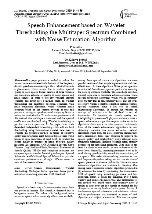
I.J. Image, Graphics and Signal Processing, 2019, 9, 44-55Published Online September 2019 in MECS (/)DOI: 10.5815/ijigsp.2019.09.05Speech Enhancement based on Wavelet Thresholding the Multitaper Spectrum Combined with Noise Estimation AlgorithmP.SunithaResearch Scholar, Dept. of ECE, JNTUK,IndiaEmail:Sunitha4949@,Dr.K.Satya PrasadRetd.Professor, Dept. of ECE, JNTUK,IndiaEmail:sprasad.kodati@Received: 26 May 2019; Accepted: 26 June 2019; Published: 08 September 2019Abstract—This paper presents a method to reduce the musical noise encountered with the most of the frequency domain speech enhancement algorithms. Musical Noise is a phenomenon which occurs due to random spectral speaks in each speech frame, because of large variance and inaccurate estimate of spectra of noisy speech and noise signals. In order to get low variance spectral estimate, this paper uses a method based on wavelet thresholding the multitaper spectrum combined with noise estimation algorithm, which estimates noise spectrum based on the spectral average of past and present according to a predetermined weighting factor to reduce the musical noise. To evaluate the performance of this method, sine multitapers were used and the spectral coefficients are threshold using Wavelet thresholding to get low variance spectrum .In this paper, both scale dependent, independent thresholdings with soft and hard thresholding using Daubauchies wavelet were used to evaluate the proposed method in terms of objective quality measures under eight different types of real-world noises at three distortions of input SNR. To predict the speech quality in presence of noise, objective quality measures like Segmental SNR ,Weighted Spectral Slope Distance ,Log Likelihood Ratio, Perceptual Evaluation of Speech Quality (PESQ) and composite measures are compared against wavelet de-noising techniques, Spectral Subtraction and Multiband Spectral Subtraction provides consistent performance to all eight different noises in most of the cases considered.Index Terms—Speech Enhancement, Wavelet thresholding, Multitaper Power Spectrum, Noise power estimation, smoothing parameter, SNR, threshold.I.I NTRODUCTIONSpeech is a basic way of communicating ideas from one person to another. This speech is degraded due to background noise .To reduce this background noise numerous speech enhancement algorithms were available, among them spectral subtractive algorithms are more popular because of their simple implementation and their effectiveness. In these algorithms Noise power spectrum is subtracted from the noisy power spectrum by assuming the noise spectrum is available. These methods introduce musical noise due to inaccurate estimate of noise. These spectral subtractive algorithms works well in stationary noise but they fails in non-stationary noise. This led to the use of low variance spectral estimation methods because spectral estimation plays a key role in speech enhancement algorithms. To reduce the variance an average of estimate can be calculated across all frequencies. To improve the speech quality and intelligibility in presence of highly non stationary noise, a speech enhancement algorithm requires noise estimation algorithms which update the noise spectrum continuously. Most of the speech enhancement applications in non-stationary scenarios use noise estimation methods algorithms which track the noise spectrum continuously. Now, researchers focus their attention to improve the speech quality and intelligibility using efficient noise estimation algorithms. Estimate of noise signal strongly depends on the smoothing parameter. If its value is too large i.e closer to one results in over estimation of the noise level. Generally, smoothing parameter is set to be small during speech activity to track the non-stationary of the speech. This makes the smoothing parameter as time and frequency dependent, taking into the consideration of speech presence or absence probability. Numerous noise estimation algorithms are available in literature. One among them is minimum statistics algorithm, proposed in [1] estimates the noise by considering the instantaneous SNR of speech using smoothing parameter and bias correction factor. It tracks the minimum over a fixed window and updates the noise PSD. The performance of this method was tested under non-stationary noise it results in large error and it is unable to respond for fast changes in increasing levels of noise power. Martín .R implemented spectral subtraction with minimum statistics and its performance was evaluated in terms of both objective and subjective measures. This was comparedagainst spectral subtraction method that uses voice activity detection which results in improved speech intelligibility measures [2].Another variant of minimum statistics suggested in [3] implements estimates noise by continuous spectral minimum tracking in sub bands. In this method a different approach was used to obtain spectral minimum, by smoothing the noisy speech power spectra continuously using a non-linear smoothing rule. This non-linear tracking provides continuous smoothing over PSD without making any distinction between speech presence and absence segments. The shortcoming of this was when noise power spectrum increases, then the noise estimate increases irrespective of changes in the noise power level. Similarly when the noisy power is decreasing then the noise power is decreasing .This will results in overestimation of speech during speech presence regions i.e clipping of speech. This method was evaluated in terms of objective and subjective quality measures it shows its superior performance over Minimum statistics algorithm. The non-uniform effect of noise on the speech spectrum affects few frequency components severely than others. This led to the use of time recursive noise estimation algorithm which updates the noise spectrum when the effective SNR in a particular band is too small [4]. In this method noise spectrum is estimated as a weighted average of past and present estimates of noisy power spectrum depending on the effective SNR in each frequency bin .This algorithm works well in tracking the non-stationary noise in case of multitalker babble noise. Another type of recursive algorithm ,which uses a fixed smoothing factor, but the noise spectrum should be updated based on the comparison of the estimated a-posteriori SNR over a threshold[5].If this a-posteriori SNR is larger than the threshold indicates that speech presence and no update is required for noise spectrum. Otherwise it is treated as a speech absence segment, which requires a noise updating. This method is well known as weighted spectral averaging. In this method the threshold value, have a significant effect on the noise spectrum estimation .If the threshold value is too small noise spectrum is underestimated, conversely the threshold value is too high then the spectrum is over estimated. Improvements to the Minimum statistics was suggested in [6] by using optimal smoothing for noise power spectral density estimation. Cohen proposed noise estimation algorithm, which uses time-frequency dependent smoothing factor which requires continuous updating depending on the speech presence probability in each frequency bin .Speech presence probability was calculated as the ratio of the noisy power spectrum to its local minimum [6].This local minimum is computed considering the smoothed noisy PSD, over a fixed window by sample wise comparison of noisy PSD. This has a short coming ,it may lag when the noise power is raising from the true noise PSD .To address this shortcoming, a different approach was suggested in[8,9] uses continuous spectral minimal tracking and frequency dependent threshold was used to identify the speech presence segments .This method was evaluated in terms of subjective preference tests over other noise estimation algorithms like MS and MCRA. This method shows better performance .Further refinement to this algorithm was reported in [10] i.e noise power spectrum estimation in adverse environments by Improved Minima Controlled Recursive Averaging (IMCRA).This method involves two steps smoothing and minimal tracking .Minimal tracking provides Voice Activity Detection in each frame whereas smoothing excludes strong speech components. Speech presence probability is calculated using a –posteriori and a-priori SNRs. This method yields in lower values of error for different types of noise considered.The structure of the paper is as follows, Section II provides Literature review , Multitaper spectral estimation and spectral refinement is given in Section III ,noise estimation by weighted spectral averaging technique was presented in section IV ,section V presents proposed speech enhancement method, results and discussion in VI and finally section VII gives conclusion.II.L ITERATURE R EVIEWThis section presents literature review on spectral subtractive type algorithms for single channel enhancement techniques. In the past, number of researchers proposed different speech enhancement methods. Most of them are based on Spectral Subtraction (SS), Statistical Model based, Sub space algorithms and Transform based methods. One of the popular noise reduction method which is computationally efficient and less complexity for single channel speech enhancement is Spectral subtraction proposed by Boll S.F for both Magnitude and Power Spectral Subtraction which itself creates a bi-product named as synthetic noise[17].A significant improvement to spectral subtraction with over subtraction factor and spectral floor parameter to reduce the musical noise given by Berouti [19]is Non –Linear Spectral subtraction . Multi Band Spectral Subtraction (MBSS) proposed by S.D. Kamath with multiple subtraction factors in non-overlapping frequency bands [18] .Ephraim and Malah proposed spectral subtraction with MMSE using a gain function based on priori and posteriori SNRs[20].Spectral subtraction based on perceptual properties using masking properties of human auditory system proposed by Virag [21].Another method in spectral subtraction with Wiener filter to estimate the noise spectrum is extended spectral subtraction by Sovka [22]. Spectral Subtraction algorithm based on two-band is Selective spectral subtraction described by He,C.and Zweig,G. [23].Spectral subtraction with Adaptive Gain Averaging to reduce the overall processing delay given by Gustafsson et al[24].A frequency dependent spectral subtraction is non-linear spectral subtraction (NSS) method conferred by Lockwood and Boudy[25].The spectral subtractive type algorithms works well in case of additive noise but fails in colored noise. To overcome this problem Hu and Loizou proposed a Speech enhancement technique based on wavelet thresholding the multitaper spectrum [11] and its performance is evaluated in terms of objective quality measures.III. M ULTITAPER S PECTRAL E STIMATION A ND S PECTRALR EFINEMENT Due to sudden changes and sporadic behavior, Speech signal can be modeled as a non- stationary signal. As time evolves the statistics like mean, variance, co-variance and higher order moments of a non-stationary signal changes over time. Spectral analysis plays a major rule in speech enhancement techniques to get accurate noise estimation. FFT method is widely used to get power spectrum estimation in most of the speech enhancement algorithms especially in spectral subtractive type methods. The estimated power spectrum obtained by FFT is reduced by variance of the estimate and energy leakage across frequencies which create bias. To avoid leakage, multiply the signal in time domain with a suitable window which having less energy in side lobes. Type of window affects the noise estimate in speech enhancement algorithms, hence selection of desirable window which provides an accurate noise estimation plays a significant role in Speech enhancement process .Generally Hamming window is preferable with less energy in side lobes but it effects the estimate by reducing leakage but not the variance. In most of the speech enhancement algorithms noise estimate is obtained by using suitable windows which reduce the bias but not the variance. The variance can be reduced by taking multiple estimates from the sample which can be achieved by using tapers. Hu and Loizou [11] used these multi-tapers to get low variance spectral estimate ,further the spectrum was refined using wavelet thresholding ,Finally this was used to improve the quality of speech signal in case of highly non-stationary noise. Results shows that this method has superior performance in terms of quality measures with high correlation between subjective listening test and objective quality measures. Speech enhancement techniques find wide range of applications like hearing aids to personal communication, teleconferencing, Automatic Speech Recognition (ASR), Speaker Authentication and Voice operated Systems. The multitaper spectrum estimator is given byS ̂mt (ω)=1L ∑Ŝpmt L−1p=0(ω) (1) WithS ̂p mt (ω)=|∑b p (m )x (m )e−jωm N−1M=0|2 (2) Here data length is given by N and b p is the p thsine taper used for spectral estimate [12] and b p is given byb p (m )=√2N+1sinπp(m+1)N+1,m =0,.N − 1 (3)Further refinement of spectrum is obtained by applying wavelet thresholding techniquesv (ω)=S ̂mt (ω)S(ω)~X 2L22L,0<ω<π (4)Where v (ω)is the ratio of the estimated multitaper spectrum to the true power spectrum .Taking logarithm on both sides, we getlogŜmt (ω)=log S (ω)+logv(ω) (5)From this equation , we conclude that sum of the true log spectrum and noise can be treated as log of multitaper spectrum. If L is at least equivalent to 5 then logv(ω) will be nearer to normal distribution and the random variable n (ω) is given byn (ω)=logv (ω)−∅(L )+log (L ) (6)Z (ω) is defined asZ (ω)=logS ̂mt (ω)−∅(L )+log (L). (7)The idea behind multitaper spectral refinement [11] can be summarized as1. Obtain the multitaper spectrum of noisy speech using orthogonal sine tapers by equation1 .2. Apply Dabauchies Discrete Wavelet Transform to get the DWT coefficients.3. Perform thresholding procedure on the DWT coefficients.4. Apply Inverse Discrete Wavelet Transform to get the refined log spectrum.Fig.1. Multiple window method for spectrum estimation by individualwindows.Fig.2. Speech signal(mtlb.wav)(a)(b)(c)Fig.3. (a),(b) and (c) Spectrum obtained by N=1,2,3.’N’ is the number oftapersFig.4. Final spectrum obtained by averagingIV.N OISE E STIMATION B Y W EIGHTED S PECTRALA VERAGINGNoise estimation algorithms works on the assumption that the duration of analysis segment is too long enough that it should contain both low energy segments and speech pauses .Noise present in analysis segment is more stationary than speech. This paper uses noise estimation based on the variance of the spectrum suggested in [12].The noise spectrum updating will take place when the magnitude spectrum of noisy speech falls within a variance of the noise estimate. The noise spectrum was updated based on the following condition.|Ŝmt(λ,K)|−σd(λ,K)<ϵ√Var d(λ,K) (8) Where Var d(λ,K)represents the instantaneous variance of the noise spectrum and ϵis a adjustable parameter, |Ŝmt(λ,K)|is multitaper magnitude spectrum and σd(λ,K) is the estimate of the noise PSD .The variance of the noise spectrum was evaluated using the recursive equationVar d(λ,K)=δ Var d(λ−1,K)+(1−δ)[|Ŝmt(λ,K)|−σd(λ,K)]2 (9)Where δis a smoothing parameter. ‘λ, is a frame index and ‘K’ is a frequency bin .The noise estimation algorithm can be summarized as ifIf|Ŝmt(λ,K)|−σd(λ−1,K)<ϵ√Var d(λ−1,K)σd(λ,K)=α σd(λ−1,K)+(1−α)|Ŝmt(λ,K)|(9)Var d(λ,K)=δ Var d(λ−1,K)+(1−δ)[|Ŝmt(λ,K)|−σd(λ,K)]2(10)Elseσ̂d(λ,K)=σ̂(λ−1,K) (11)This paper uses this weighted spectral averaging method for noise estimation from noisy power spectrum using the parameters δ=α=0.9 and ϵ=2.5.V.P ROPOSED M ETHODThe implementation details of speech enhancement method can be given as follows:1. Obtain the multi taper estimate of the Noisy speech using sine tapers using equation12. Perform spectral refinement with the help of wavelet thresholding procedure, which involves Forward Discrete Wavelet Transform (FDWT), Thresholding and Inverse Discrete Wavelet Transform (IDWT).In this paper Dabauchies wavelets were used at level 5 decompition by using both soft and hard thresholding.3. Compute Z(ω)from the equation (6) and apply Discrete Wavelet Transform to Z(ω)then threshold the multitaper spectrum for further refinement of spectrum and the refined log spectrum .4. Estimate of the noise can be evaluated using weighted spectral recursive averaging algorithm discussed in section IV.5. Perform multitaper spectral subtraction between the refined log spectrum of noisy speech and noise spectrumto get an estimate of Clean Speech spectrum .S ̂x ωmt (ω)=S ̂y ωmt (ω)−S ̂n mt (ω) (12)and it results in negative values which are rounded asS ̂X mt ={S ̂y mt −S ̂n mt , if S ̂y mt >S ̂n mt βS ̂n mt , if S ̂y mt ≤ S ̂n mt ,(13) Where ‘ β’ is spectral floor parameter .6. Finally the enhanced speech Signal can be reconstructed using Inverse Discrete Fourier Transform and overlap- add method.Fig.5. Block diagram of proposed methodVI. R ESULTS A ND D ISCUSSIONAssessment of speech enhancement techniques can be done either by using objective quality or subjective listening tests. Comparative analysis of original speech and processed speech signals by a group of listeners is known as subjective listening test based on human auditory system.. Which involves a complex process and it is difficult to identify the persons with good listening skills. While objective evaluation is done on mathematical comparison of clean and enhanced signals .In order to calculate the objective measures, the speech signal is first divided into frames of duration of 10-30 msec. This result in a single measure which gives the average of distortion measures calculated for all the processed frames. This section gives the performance analysis of the proposed method by using four numbers of bands. Simulations were performed in the MATLAB environment. NOIZEUS is used as a speech corpus which is available at [15] and used by the most of the researchers, containing 30 sentences of six different speakers, three are male and other three are female speakers originally sampled at 25 KHz and down sampled to 8 KHz with 16 bits resolution quantization. Clean Speech is distorted by eight different real-world noises (babble, airport, station, street, exhibition, restaurant, car and train) at three distinct ranges of input SNR (0dB, 5dB, 10dB). In this algorithm speech sample is taken from a male speaker, English sentence is ”we can find joy in the simplest things”. This paper presents the performance evaluation based on different quality measures which are segmental-SNR, Weighted Slope Spectral Distance(WSSD) [13], Log Likelikelihood Ratio, Perceptual Evaluation of Speech Quality (PESQ) [14]and three different composite measures[13]. A. Segmental SNR (seg-SNR)To improve the correlation between clean and processed speech signals summation can be performed over each frame of the signal [13] this results in segmental SNR .The segmental Signal-to-Noise Ratio (seg-SNR) in the time domain can be expressed asSNR seg =10M∑log 10M−1M=0∑x 2(n)Nm+N−1n=NM∑(x (n)−x̂(n))2Nm+N−1n=NM (14)Here x(n) shows the original speech signal. x(n)̂ is theprocessed speech signal, frame length is given by N andthe number of frames is given by M. The geometric mean of all frames of the speech signal is seg-SNR [10], whose value was limited in the range of [-10, 35dB] B. Log Likelihood Ratio (LLR)This measure was based on LPC analysis of speech signal.LLR (a x ⃗⃗⃗⃗ ,ax ̂)=log (a ⃗ x̂R x a ⃗ x ̂T a ⃗ x R x a⃗ x T ) (15)a x ,a x ̂Tare the LPC coefficients of the original andprocessed signals. R x is the autocorrelation matrix of the original signal .In LLR denominator term is always lower than numerator therefore LLR is always positive [13] and the LLR values are in the range of (0-2).Multitaper spectral estimation using sine-tapersWavelet thresholding the Multitaper spectrumSpectralSubtractionNoise estimation by weighted spectral averagingSignal framing using Hamming WindowInverse DFT &OLANoisy SpeechEnhanced SpeechC. Weighted Slope Spectral Distance(WSSD)This measure can be evaluated as the weighted difference between the spectral slopes in each band can be computed using first order difference operation[13].Spectral slopes in each band of original and processed signals are given byWSSD=1M ∑∑W(j,m)(X x(j,m)−X X̂(j,m))2Kj=1∑W(j,m)Kj=1M−1M=0(16)D. Perceptual Evaluation of Speech Quality (PESQ) One among the objective quality measures which provides an accurate speech quality recommended by ITU_T [14] which involves more complexity in computation. A linear combination of average asymmetrical disturbance A ind and average disturbance D ind is given by PESQ.PESQ=4.754-0.186D ind-0.008 A ind (17) E. Composite MeasuresLinear combination of existing objective quality measures results in a new measure [10].This can be evaluated by using linear regression analysis. This paper uses the multiple linear regression analysis to obtain the following new composite measures [13].These composite measures were measured on a five-point scale.(i) Signal Distortion(C sig): The linear combination of PESQ, LLR and WSSD measures results in a new composite measure named as Signal Distortion [13].This is evaluated using the following equationC sig=3.093-1.029*LLR+0.603*PESQ-0.009*WSSD(18)(ii) Noise intrusiveness(C bak): The linear combination of PESQ, seg-SNR and WSSD measures results in anew composite measure named as noise Distortion [13]. This is evaluated using the following equation.C bak=1.634+0.478*PESQ+0.007*WSSD+0.063*seg-SNR(19)(iii) Overall Quality (C ovl): Overall Quality is formed by Linear combination of LLR ,PESQ and WSSD measures and is given byC ovl=1.594+0.805*PESQ-0.512*LLR-0.007*WSSD(20) Scale of signal degradation, background intrusiveness and overall quality measures are shown in table 1,2,3.Table 1. Scale of Signal DistortionTable 2. Scale of Background IntrusivenessTable 3. Scale of Overall qualityTo obtain objective quality measures for the proposed method first the multitaper spectrum was obtained using sine tapers. Further spectral refinement is achieved through wavelet thresholding the multitaper spectrum .Then noise spectrum is estimated using weighted spectral averaging. The results were compared against Wavelet de-noising using hard thresholding (WDH) and soft thresholding (WDS) suggested in [16], Spectral subtraction(SS) [17] and Multi Band Spectral Subtraction (MBSS) [18].Table 4. Objective quality measures Segmental SNR(seg_SNR),Log Likelihood Ratio(LLR),Weighted Slope Spectral Distance (WSSD),PerceptualEvaluation of Speech Quality(PESQ)Table 5. Composite measures(C sig, C bak, C ovl) for eight different types of noises(a)(b)(c)(d)(e)(f)(g)Fig.6. a)Segmental SNR b)Log Likelihood Ratio c)Weighted spectral slope distance d)PESQ e)Signal Distortion (C sig) f) Background intrusiveness (C bak) g) Overall quality (C ovl) measures against inputSNR.Fig.7. Time domain and spectrogram representation of Clean Speech noisy speech and enhanced speech signals by SS[17],MBSS[18],WDH,WDS[16] ,Wavelet thresholding the multi taper spectrum[11] and proposed method.VII. C ONCLUSIONFrom the results shown in table.4, performance of wavelet de-noising techniques is very poor in terms of all objective quality measures i.e lower values of segmental SNR and PESQ and higher values of LLR and WSSD in all the cases considered when compared to other techniques. The proposed method exhibits its superior performance i,e higher values of segmental SNR and PESQ for all types of noises at three levels of input SNR against all the methods considered. The performance of proposed method decreases in terms of LLR and WSSD when compared to Multi Band Spectral Subtraction method. Composite measures were shown in table.5, indicates that the proposed method provides improvement in terms of all three composite measures when compared to all the four different methods considered. The same results can be shown in the form of graphs by taking average of all eight different noises at three levels in figure .6 from a to g. From the results it can be concluded that the proposed method is suitable for higher values of segmental SNR, PESQ and composite measures.Figure7.,shows the time domain and frequency domain representation of noisy speech, noise and enhanced speech signals for various methods like Spectral Subtraction [17],Multi Band Spectral Subtraction[18], Wavelet de-noising techniques with both soft and hard thresholding [16],Wavelet thresholding the Multitaper spectrum for speech enhancement[11] and proposed methods.Spectrograms are widely used in speech processing to plot the spectrum of frequencies as it varies with time. The spectrogram can be evaluated as a sequence of FFTs computed over a windowed signal of duration of 20ms In the time domain Enhanced speech signal from Spectral subtractive type algorithm introduces musical noise; it was eliminated in the Multi Band Spectral Subtraction the same can be observed in spectrograms. Wavelet de-noising techniques shows its performance in suppression of noise. The proposed method gives the enhanced signal closer to original clean speech signal and spectrogram also closer to the spectrogram of clean speech signal.A CKNOWLEDGEMENTI would like to take this opportunity to express my profound gratitude and deep regard to my Research Guide Dr.K.Satya Prasad for his exemplary guidance, valuable feedback and constant encouragement throughout the duration of the research. His valuable suggestions were of immense help throughout research. Working under him was an extremely knowledgeable experience for me. I would also like to give my sincere gratitude to the authors Hu and Loizou, for inspiring me with their research papers in the field of speech enhancement along with objective quality measures.R EFERENCES[1]R.Martin, “An efficient algorithm to estimate theinstantaneous SNR of speech signals”, proceedings of Euro speech ,Berlin,pp.1093-1096,1993.[2]R.Martin, “Spectral subtraction based on minimumstatistics, Proceedings of European Signal Processing,U.K,pp.1182-1185,1994.[3]G.Doblinger, “Computationally efficient speechenhancement by spectral minima tracking in sub bands”, proceedings of Euro speech ,Spain, pp:1513-1516,1995. [4]H.Hirch, and C.Ehrlicher, “Noise estimation techniquesfor robust speech rec ognition”, proceedings of IEEE International Conference on Acoustic Speech Signal Processing, MI, pp.153-156,1995.[5]R.Martin, “Noise Power Spectral Density Estimationbased on Optimal Smoothing and Minimum statistics”, IEEE Transactions on Audio, Speech Processing pp.504–512, 2001.[6]I.Cohen, “Noise Estimation by Minima controlledrecursive averaging for robust speech enhancement”, IEEE Signal Processing. Letter, pp.12–15,2002[7]I.Cohen, “Noise spectrum Estimation in adverseenvironments: Improved Minima controlled recursive averaging”, IEEE Transactions on Audio, Speech Processing, pp.466-475, 2003.[8]L.Lin ,W.Holmes and E.Ambikairajah , “Adaptive noiseestimation algorithm for speech enhancement”,Electron .Lett,754-555,2003[9]Loizou, R.Sundarajan,Y. Hu,”Nois e estimation Algorithmwith rapid Adaption for highly non-stationary environments “Proceedings on IEEE International Conference on Acoustic Speech Signal Processing,2004.[10]Loizou, R.Sundarajan, “A Noise estimation Algorithm forhighly non-stationary Envi ronments”. Speech Communication,48, Science Direct , pp.220-231,2006. [11]Yi.Hu ,P.C .Loizou.,"Speech enhancement based onwavelet thresholding the multitaper spectrum”, IEEE Transactions on Speech and Audio Processing,pp.59-67,2004.[12] C.Ris and S.Dupont, “Assessing local noise levelestimation methods: Applications to noise robust ASR”, Speech Communication, pp.141-158,2001.[13]Yi.Hu ,P.C .Loizou.,"Evaluation of objective QualityMeasures for Speech Enhancement " ,IEEE Transactions on Audio, Speech and Language Processing pp.229-238,Jan.2008.[14]ITU_T Rec, “Perceptual evaluation of speechquality(PESQ), An objective method for end to end speech quality assessment of narrowband telephone networks and speech codecs”.,International Telecommunications Union ,Geneva Switzerland, February 2001.[15] A Noisy Speech Corpus for Assessment of SpeechEnhancement Algorithms. https: // / Loizou /speech/noizeous.[16]DL.Donoho, “De-noising by soft thresholding “,IEEErm.Theory,41(3), 613627,1995.[17]Boll,S.F, “Suppression of acoustic noise in speech usingspectral subtraction”. IEEE Transactions on Acoustics Speech and Signal Processing, 1979,27(2), 113–120.。
Vibration Analysis Definitions(英文)

Vibration Analysis DefinitionsA great resource to look up vibration analysis techniques and explanations of diagnoses.Analysis Definitions: UnbalanceSymptoms: 1X radial (V & H)The technical way to describe unbalance is as a condition where "a shaft's geometric centerline and mass centerline do not coincide”, or where "the center of mass does not lie on the axis of rotation”. In other words, there is a heavy spot somewhere along the shaft.There are two types of unbalance: static and couple. Normally there is a combination called "dynamic” if the rotor is not narrow compared to its diameter.We expect to see a high peak in the spectrum at 1X turning speed of the shaft. It is often higher in the horizontal direction compared with the vertical direction due to stiffness.Waveform: The waveform should be very sinusoidal; if not there may also be misalignment, looseness or other fault condition in addition to unbalance. View in units of velocity if possible.Phase: Phase is the best indicator. Compare vertical to horizontal phase – there should be a 90° phase shift.See also static and couple unbalance, and unbalance for vertical machines and overhung machines.Unbalance: Static imbalanceSymptoms: 1X radial (V & H)Expect to see a large peak in the spectrum at the shaft turning speed (1X) in the vertical and horizontal axis. Axial 1X vibration will be low.The simplest type of unbalance is equivalent to a heavy spot at a single point in the rotor. This is called a static unbalance because it will be present even if the rotor is not turning - if placed in frictionless bearings the rotor will turn so the heavy spot is at the lowest position. Static unbalance can be corrected with a single-plane balance.Static unbalance results in 1X forces on both bearings of the rotor, and the forces on both bearings are always in the same direction. The vibration signals from them are "in phase" with each other.Spectrum: High 1X in the radial directions. Low in the axial direction.Waveform: The waveform will be very sinusoidal when viewed in units of velocity. If it is not sinusoidal then there may (also) be misalignment, cocked bearing, a bent shaft or some other fault condition.Amplitude: Compare vertical to horizontal vibration on a horizontal machine. If horizontal >2X vertical amplitude then suspect foundation looseness or resonance.Phase: Look for 90°phase shift between vertical and horizontal. For pure static unbalance, phase at bearings at either end of the rotor will be in-phase.Unbalance: Couple imbalanceSymptoms: 1X radial (V & H)Expect to see a large peak in the spectrum at the shaft turning speed (1X) in vertical and horizontal axis. Axial 1X vibration will be low.A rotor with couple unbalance may be statically balanced (it may seem to be perfectly balanced ifplaced in frictionless bearings), but when rotated, it will produce centrifugal forces on the bearings, and they will be of opposite phase. > A two-plane balance is required to correct couple unbalance.Spectrum: High 1X in the radial directions. Low in the axial direction.Waveform: The waveform will be very sinusoidal when viewed in velocity. If it is not sinusoidal then there may (also) be misalignment, cocked bearing or some other fault condition.Amplitude: Compare vertical to horizontal vibration on a horizontal machine. If horizontal >2X vertical amplitude then suspect looseness or resonance.Phase: Look for 90° phase shift between vertical and horizontal. For pure couple unbalance, phase at bearings at either end of the rotor will be 180° out-of-phase.Unbalance: Dynamic unbalanceSymptoms: 1X radial (V & H)Dynamic unbalance is a combination of static and couple unbalance. It normally occurs in rotors that are long compared to their diameter. Dynamic unbalance is the most common form of unbalance in these sorts of rotors. A two-plane balance is required to correct dynamic unbalance.Spectrum: High 1X in the radial directions. Low in the axial direction.Waveform: The waveform should be very sinusoidal; if not there may also be misalignment, looseness or other fault condition in addition to unbalance. View in units of velocity if possible.Phase: Phase is the best indicator. Look for 90°phase shift between vertical and horizontal. Phase at bearings at either end of the rotor will be between 30°and 150°out-of-phase.See also static and couple unbalance.Unbalance: Vertical machinesSymptoms: 1X radial (horizontal)The spectrum will show a high amplitude peak at 1X turning speed when measured in the radial direction (horizontal or tangential).To distinguish motor unbalance from pump unbalance, it may be necessary to break the coupling and run the motor solo while measuring 1X. If the 1X level is still high, the problem is the motor;otherwise it is the pump.Spectrum: High 1X in the radial directions.Waveform: The waveform will be very sinusoidal when viewed in units of velocity.Amplitude: Amplitude will be higher where the stiffness is lowest. Typically amplitude will be highest on top of motor, and it will be lowest in the direction of piping.Phase: Look for 90° phase shift between readings taken 90° apart. All readings taken in the same direction should be in-phase.Unbalance: Overhung machinesSymptoms: High 1X axial, 1X radial (V & H)In an overhung or cantilevered machine, you will see a high amplitude peak at 1X turning speed in the vertical, horizontal and axial directions.We see the high 1X in axial because the unbalance creates a bending moment on the shaft, causing the bearing housing to move axially. Examples of overhung rotors are close-coupled pumps, axial flow fans, and small turbines.Spectrum: High 1X in the radial directions but highest in the axial direction.Waveform: The waveform will be very sinusoidal when viewed in units of velocity.Phase: Look for 90°phase shift between vertical and horizontal. Axial readings on both bearings will be in-phase. Radial phase readings on both bearings will be in-phase.Analysis Definitions: MisalignmentFrequency: 1X axial, 2X radial (V & H)Misalignment is a condition where the centerlines of coupled shafts do not coincide.Misalignment is common due to poor alignment practices or because of thermal growth, shifting foundations, pipe strain, etc.If the misaligned shaft centerlines are parallel but not coincident, then the misalignment is said to be parallel (or offset) misalignment. > If the misaligned shafts meet at a point but are not parallel, then the misalignment is called angular misalignment. The vibration does not always change in predictable ways when shafts are misaligned.Most misalignment cases are a combination of parallel and angular misalignment. Diagnosis, asa general rule, is based upon dominant vibration at twice the rotational rate (2X) with increasedrotational rate (1X) levels acting in the axial and in either the vertical or horizontal directions.Spectrum: We expect to see a high 1X peak in the axial direction due to angular (gap) misalignment, and high peaks at 1X, 2X, 3X, and even 4X and 5X in the radial direction due to the parallel (offset) misalignment.horizontal at the other end of the same component.Phase: The components (e.g. motor and pump) will be out-of-phase axially due to angular misalignment. When comparing vertical and horizontal phase readings, they may be in-phase or 180°out-of-phase. Vertical phase readings taken on opposites sides of the coupling (e.g. motor drive end and pump drive end) will be out-of-phase.Waveform: The waveform will be a combination of 1X, 2X and possibly other sources and may therefore include a "wobble” or take on the "M” or "W” shape.Misalignment: Parallel (Offset)Symptoms: 2X radial, small 1X radial (V & H)If the misaligned shaft centerlines are parallel but not coincident, then the misalignment is said to be parallel (or offset) misalignment.Misalignment is common due to poor alignment practices or because of thermal growth, shifting foundations, pipe strain, etc. The vibration does not always change in predictable ways when shafts are misaligned.Parallel misalignment produces both a shear force and bending moment on the coupled end of each shaft. Spectrum measurements are very useful; however it can be confused with other faults. Phase readings provide additional evidence.Spectrum: We expect to see high peaks at 1X, 2X, 3X, and even 4X and 5X in the radial direction due to the parallel (offset) misalignment. 2X can be quite high compared to 1X vibration. The presence of 3X, 4X, 5X etc. will depend on coupling type and degree of misalignment.horizontal at the other end of the same component.Phase: When comparing vertical and horizontal phase readings, they may be in-phase or 180°out-of-phase. Vertical phase readings taken on opposites sides of the coupling (e.g. motor drive end and pump drive end) will be out-of-phase.Waveform: The waveform will be a combination of 1xTS, 2xTS and possibly other sources and may therefore include a "wobble" or take on the "M" or "W" shape.Misalignment: Angular (Gap)Symptoms: 1X axial, small 2X axial, small 1X radialIf the misaligned shafts meet at a point but are not parallel, then the misalignment is called angular or gap misalignment.Misalignment is common due to poor alignment practices or because of thermal growth, shifting foundations, pipe strain, etc. The vibration does not always change in predictable ways when shafts are misaligned.Angular misalignment produces a bending moment on each shaft, and this generates a strong vibration at 1X and some vibration at 2X in the axial direction at both bearings.There will also be fairly strong radial (vertical and horizontal) 1X and 2X levels, however these components will be in phase.Spectrum: We expect to see a high 1X peak in the axial direction, and a small 2X and 3X peak depending upon the "linearity” of the vibration.There may also be 1X and 2X in the radial direction.Phase: The components (e.g. motor and pump) will be out-of-phase axially due to angular misalignment. Measure axially on the components on either side of the coupling and remember to compensate for sensor direction. The components are likely to be out-of-phase radially across the coupling.Waveform: The waveform in the axial direction will be dominated by the sinusoidal 1X vibration. Analysis Definitions: Rolling element bearingsSymptoms: Non-synchronous vibration and othersThere are a large number of fault conditions that can be associated with rolling element bearings, including: stage one-four bearing wear, lubrication problems, cocked bearing, fluting/EDM, skidding, and looseness. We have included information on each of these possible fault conditions in this app.∙Lubrication: Insufficient lubrication.∙Wear/cracks/spalls: Damage on the inner or outer race and damage on the rolling elements. Damaged cages are harder to detect with vibration analysis.∙Fluting/EDM: Current passing through bearing – washboard pattern etched on raceways. ∙Cocked bearing: Inner race not true on shaft or outer race not true in housing.∙Excessive clearance: Due to excessive wear or poor bearing selection.∙Skidding: Rolling elements skidding over inner race when out of the load zone.∙Loose on shaft: Inner race sliding on shaft.∙Loose in housing: Outer race turning in housing.Spectrum analysis is very useful, but time waveform analysis should also be used. High frequency techniques (Enveloping, Demodulation, PeakVue™, Shock Pulse™ and Spik e Energy™) are very effective at detecting many of the fault conditions.Lubrication: High frequency vibration.Wear/cracks/spalls High frequency vibration initially, extending into lower frequency vibration as the fault becomes worse. Non-synchronous frequencies.Fluting/EDM: Raised noise floor with peaks in range 100-180 kCPM.Cocked bearing: Axial vibration – phase readings on face of component aid in the diagnosis.Excessive clearance: High harmonics of turning speed (1X).Skidding: Raised noise floor with peaks in range 100-180 kCPM.Loose on shaft: 3X peak with harmonics.Loose in housing: 4X peak.Rolling element bearings: Stage one faultSymptoms: Very low amplitude, very high frequency vibrationAt the first signs of lack of lubrication or minor bearing damage the vibration amplitude will be very low. The vibration generated will be very high frequency; possibly over 10 kHz.Traditional spectrum analysis and time waveform techniques will not detect the fault. High frequency techniques such as ultrasound may detect the lubrication problem, and techniques such as Enveloping, Demodulation, PeakVue™, Shock Pulse™ and Spike Energy™ may detect the fault in Stage One.Waveform: Will not help in stage oneHigh frequency techniques:Enveloping, Demodulation, PeakVue™, Shock Pulse™ and Spike Energy™ may be effective but only if the filter is set correctly and the accelerometer (or shock pulse sensor) is correctly mounted.Rolling element bearings: Stage two faultSymptoms: Very low amplitude, very high frequency vibrationAs the bearing fault develops, techniques such as enveloping and demodulation will be more successful than when the fault was in Stage One, however it is unlikely that a linear velocity spectrum will indicate that the fault exists. If the spectrum is displayed in log format, or you use units of acceleration, there is a greater chance of success.The time waveform viewed in units of acceleration will show signs of the defect, especially when applied to slow speed machines.PeakVue™, Shock Pulse™, Spike Energy™ can all be used successfully if set up correctly and the accelerometer is mounted correctly.Waveform: May be effective. Most likely to be effective on slow speed machines.High frequency techniques:Enveloping, Demodulation, PeakVue™, Shock Pulse™ and Spike Energy™ may be effective but only if the filter is set correctly a nd the accelerometer (or shock pulse sensor) is correctly mounted.Rolling element bearings: Stage three fault: outer raceSymptoms: Non-synchronous harmonicsWhen the bearing fault reaches stage three the damage is more severe and will be visible if the bearing is removed. The velocity spectrum can be used to detect the fault in addition to the time waveform (in velocity or acceleration) and high frequency techniques (demodulation, enveloping, PeakVue™, Shock Pulse™, and Spike Energy™).If the damage is on the outer race there will be an impact each time the ball or roller comes into contact with the damaged area. The amplitude should be constant, therefore no modulation (or sidebands). If the outer race is rotating there will be 1X sidebands.Spectrum: Look for harmonics of a frequency that is not an even multiple of shaft turning speed(e.g. 4.31X). If the inner race is rotating you should not expect to find sidebands.BPFI>BPFO>BSF>1X>FTBPFI + BPFO = NB½-(1.2/NB)BSF~½[(NB/2)-(1.2/NB)]BPFO≈(NB/2)-1.2BPFI≈(NB/2)+1.2Waveform: Impacts should be visible in the time waveform. You will need to have a large number of samples and a small number of shaft rotations to view the impacts.High frequency techniques:Enveloping, Demodulation, PeakVue™, Shock Pulse™ and Spike Energy™ may be effective but only if the filter is set correctly and the accelerometer (or shock pulse sensor) is correctly mounted.Rolling element bearings: Stage three fault: inner raceSymptoms: Non-synchronous harmonics & 1X sidebandsWhen the bearing fault reaches stage three the damage is more severe and will be visible if the bearing is removed. The velocity spectrum can be used to detect the fault in addition to the time waveform (in velocity or acceleration) and high frequency techniques (demodulation, enveloping, PeakVue™, Shock Pulse™, and Spike Energy™).If the damage is on the inner race there will be an impact each time the ball or roller comes into contact with the damaged area. The amplitude will be highest when the damaged area is in the load zone therefore there will be 1X sidebands.Spectrum: Look for harmonics of a frequency that is not an even multiple of shaft turning speed(e.g. 6.31X) with 1X sidebands. If the outer race is rotating you should not expect to findsidebands.BPFI>BPFO>BSF>1X>FTBPFI + BPFO = NBFT≈½-(1.2/NB)BSF~½[(NB/2)-(1.2/NB)]BPFO≈(NB/2)-1.2BPFI≈(NB/2)+1.2Waveform: Impacts should be visible in the time waveform. You will need to have a large number of samples and a small number of shaft rotations to view the impacts.High frequency techniques:Enveloping, Demodulation, PeakVue™, Shock Pulse™ and Spike Energy™ may be effective but only if the filter is set correctly and the accelerometer is correctly (or shock pulse sensor) mounted.Rolling element bearings: Stage three fault: ball damageSymptoms: Non-synchronous harmonics & FTF sidebandsWhen the bearing fault reaches stage three the damage is more severe and will be visible if the bearing is removed. The velocity spectrum can be used to detect the fault in addition to the time waveform (in velocity or acceleration) and high frequency techniques (demodulation, enveloping, PeakVue™, Shock Pulse™, and Spike Energy™).If the damage is on the balls or rollers there will be an impact each time the damaged area comes into contact with the inner or outer race. The amplitude will be highest when the damaged ball is in the load zone therefore there will be FTF (cage) sidebands.Spectrum: Look for harmonics of a frequency that is not an even multiple of shaft turning speed(e.g. 3.31X) with FTF (cage) sidebands (approx 0.46X).BPFI>BPFO>BSF>1X>FTBPFI + BPFO = NBFT≈½-(1.2/NB)BSF~½[(NB/2)-(1.2/NB)]BPFO≈(NB/2)-1.2BPFI≈(NB/2)+1.2Waveform: Impacts should be visible in the time waveform. You will need to have a large number of samples and a small number of shaft rotations to view the impacts.High frequency techniques:Enveloping, Demodulation, PeakVue™, Shock Pulse™ and Spike Energy™ may be effective but only if the filter is set correctly and th e accelerometer (or shock pulse sensor) is correctly mounted.Rolling element bearings: Stage four faultSymptoms: Non-synchronous harmonics & noiseWhen the bearing fault reaches stage four the bearing has significant damage and should be replaced. The calculated forcing frequencies may change due to changes in geometry. With time the tell-tale harmonics and sidebands may disappear. Instead the noise floor will rise up and methods such as Shock Pulse™ may trend downwards. As the clearance in the bearing increases due to wear, you will see signs of looseness (1X harmonics).High frequency techniques become less effective as the condition worsens. Overall levels will increase, and the velocity spectrum will show the fault clearly.Spectrum: Expect classic non-synchronous harmonics and sidebands to disappear. Spectrum will become very noisy –the noise floor will lift up ("haystacks” will appear in certain areas).As clearance increases, look for 1X harmonics.Waveform: As vibration becomes noisier and more random, the waveform will also become noisier and less useful.High frequency techniques: As the damage becomes more severe, the periodicity is lost, and the high frequencies are no longer generated. The noise floor of envelop spectra will rise up and swallow the peaks. Shock Pulse™ and Spike Energy™ may trend downwards.Rolling element bearings: Cocked bearing: on shaftSymptoms: 1X, 2X, and 3X axialA cocked bearing, which is a form of misalignment, will generate considerable axial vibration.Peaks will often be seen at 1X, 2X, as well as 3X.The bearing can be cocked on the shaft or in the housing. If it is cocked on the shaft then it will "wobble” as it rotates generating a rotating vibration – phase can detect this vibration.Given that there is such a strong axial vibration, it can be confused with misalignment, and with unbalance in an overhung pump or fan. The presence of peaks at 2X and 3X would indicate a cocked bearing condition over unbalance however.Use phase to accurately diagnose this condition.Spectrum: Look for a raised 1X and 2X peak. Phase is the key indicator.Phase: Take readings at 12:00, 3:00, 6:00 and 9:00 (or at any four positions 90° apart). The vibration amplitude should be similar at those positions but the phase should change by approximately 90°. You can do this with a two-channel analyzer by comparing 12:00 to 3:00, and then 3:00 to 6:00 etc.Rolling element bearings: Cocked bearing: in housingSymptoms: 1X, 2X, and 3X axialA cocked bearing, which is a form of misalignment, will generate considerable axial vibration.Peaks will often be seen at 1X, 2X, as well as 3X.The bearing can be cocked on the shaft or in the housing. If it is cocked in the housing then the vibration will more closely mimic misalignment. There will be two points on either side of the shaft on the face of the component where the amplitude will be highest and the vibration will be 180°out-of-phase.Given that there is such a strong axial vibration, it can be confused with misalignment, and with unbalance in an overhung pump or fan. The presence of peaks at 2X and 3X would indicate a cocked bearing condition over unbalance however.Use phase to accurately diagnose this condition.Spectrum: Look for a raised 1X and 2X peak. Phase is the key indicator.Phase: Take readings on the bearing housing around the shaft and find the highest amplitude. Measure on the opposite side of the shaft and look for approximately 180° phase difference. Phase readings taken 90° from those points will not exhibit a 180° phase difference across the shaft.Rolling element bearings: Fluting EDMSymptoms: Series of peaks commonly between 100k CPM and 180k CPMCurrent passing through the bearings will damage the bearings. A rippled pattern will be left on the bearing raceways as arcing occurs.The spectrum will have a series of peaks at high frequency separated by BPFO.This condition is common with DC motors and now with VFDs as well.Spectrum: Often there will be a series of peaks that will rise up at a high frequency, commonly between approximately 100,000 CPM and 180,000 CPM (1600 Hz to 3000 Hz). The peaks are commonly spaced by the outer race BPFO frequency. It is believed that the vibration is excitinga resonance.Waveform: The fault will be indicated, but the spectrum is the best tool.HFD: Depending upon your filter settings, the HFD techniques should indicate that the bearing is emitting a higher level of high frequency vibration.Rolling element bearings: Rolling elements skiddingSymptoms: Elevated noise floor plus BPFO or BPFI peaks protruding above noise floorIf a bearing is correctly selected for its application, and the lubricant is functioning correctly, and there is adequate load on the rolling elements, then the rolling elements should continuously roll around the raceways. However it is not uncommon for the rolling elements to slide or skid from time to time when these conditions are not met. This is more common on non-drive-end bearings, especially on vertical machines, and far more common with cylindrical roller bearings (as against deep groove ball bearings).You may hear the skidding occurring in the bearing, and you should look in the spectrum for an area of elevation, typically between 100 kCPM and 180 kCPM. Peaks of BPFO or BPFO may also be amplified in this region.Spectra: Look for the raised noise floor in the region of 100-180 kCPM with BPFO or BPFI peaks protruding above the "hump”.Tip: Give the bearing a shot of grease to see if that makes a difference. Listen for the skidding sound – it may be intermittent. You may observe a difference if the temperature of the bearing varies (due to environment or operational changes) as the viscosity of the lubricant may change.Waveform: Look for signs of skidding.IR: You may be able to detect a temperature change with a spot radiometer or IR camera.HFD: Depending upon your filter settings, the HFD techniques should indicate that the bearing is emitting a higher level of high frequency vibration.Visual: When you replace the bearing, look at the surfaces for tell-tale signs of skidding. Rolling element bearings: Inner race sliding on shaftSymptoms: Raised 3X peak with harmonicsIf the bearing is not installed correctly, the inner race may slide on the shaft – i.e. not always turn at the same speed as the shaft. Depending upon the nature of the sliding, the vibration spectrum may have an elevated 3X peak and there may be harmonics of the 3X frequency. If the sliding motion is intermittent, i.e. it slides a little then stops, slides a little then stops, then you may not observe the change in the spectrum. However if it is constantly sliding then the vibration pattern should change accordingly.Spectra: Look for the high 3X peak and harmonics (6X, 9X, etc.).Visual or strobe: If it is possible to view the bearing in the machine (by removing a cover if necessary), you can use a strobe synchronized to the shaft speed to see whether the inner raceis consistently turning at the same rate as the shaft. If the machine can be stopped then you may add a mark on the shaft and the inner race to determine whether there is relative motion.Waveform: Time waveform analysis can be used to detect the condition, especially if the movement is intermittent.When you remove the bearing check the shaft and the inside of the inner race for tell-tale signs of sliding.Rolling element bearings: Outer race loose in housingSymptoms: Elevated 4X peakIf the bearing is not installed correctly within the housing, the outer race may move relative to the housing; it may begi n to spin and even "rattle” within the housing. The peaks at 4X running speed may be elevated when this occurs.If it is possible to view the bearing within the machine (by removing a cover if necessary), you will be able to see if the outer race is moving relative to the bearing housing. If the machine can be stopped then you may add a mark on the housing and the outer race to determine whether there is relative motion.Time waveform analysis will also indicate if the outer race is loose in the housing.When the bearing is removed, the outside of the outer race should be observed for tell-tale signs of looseness.Analysis Definitions: LoosenessSymptoms: Rotating: 1X harmonics / Structural: 1X horizontal / Pedestal bearing: 1X, 2X, and 3X verticalRotating looseness is caused by excessive clearance between rotating and stationary elements of the machine such as in a bearing, while non-rotating looseness is a looseness between two normally stationary parts, such as a foot and a foundation, or a bearing housing and a machine.Structural looseness, or looseness between a machine and its foundation, will increase the 1X vibration component in the direction of least stiffness. This is usually the horizontal direction, but it depends on the physical layout of the machine.Spectrum: Each type of looseness has its own special characteristic. Rotating looseness will generate a large number of harmonics and may cause the noise floor to rise. Structural looseness will not cause harmonics unless there is impacting –simple "weakness” or "flexibility”will generate high amplitude 1X peaks in the direction of least stiffness.Phase: Phase can be a very useful tool. Rotating looseness generates "random” vibration, so the phase is erratic. Structural looseness will often have one component vibrating (the foot of the motor) and one stationary (the foundation) –you can therefore look for a 180°phase difference between the stationary and vibrating component.。
- 1、下载文档前请自行甄别文档内容的完整性,平台不提供额外的编辑、内容补充、找答案等附加服务。
- 2、"仅部分预览"的文档,不可在线预览部分如存在完整性等问题,可反馈申请退款(可完整预览的文档不适用该条件!)。
- 3、如文档侵犯您的权益,请联系客服反馈,我们会尽快为您处理(人工客服工作时间:9:00-18:30)。
Analysis of Vibration and Noise of Induction Motor Equipped with Concentric
Single-Double-Layer Star-Delta Winding*
Abstract: Compared with changing the structure of a motor that has been manufactured, changing the type of stator winding is an economical and time-saving method to reduce the vibration and noise. Thus, a concendelta (CSDLSD) winding for an induction motor is described in this paper with the aim of reducing the noise of the motor. By planning the turns relationship between the two parts of the winding, the harmonic component of the air-gap magnetic field can be decreased. Besides this, through adjusting the turns ratio in each slot of concentric winding per phase respectively, the waveform of the air-gap magnetic field becomes closer to a sinusoidal type. Three motors equipped with the CSDLSD winding and another two types of stator winding were analyzed. The theoretical analysis and the two-dimensional finite element method (2D-FEM) were combined to study the relationship between the harmonics of the air-gap magnetic field and the stator winding. Finally, a 2D fast Fourier transformation (2D-FFT) method was used to obtain the time-frequency spectrum of the air-gap flux density and electromagnetic excitation force, and compared with a natural vibration wave. The noise distribution was obtained using the harmonic response. The results of the theoretical analysis, 2D-FEM, 2D-FFT, and harmonic response corroborate each other such that the motor applying CSDLSD winding could reduce both the vibration and noise.
Keywords: Induction motor, concentric single-double-layer star-delta winding, 2D-FFT, vibration
1 Introduction1
Noise is a perennial issue of induction motors, research on motor vibration and noise has attracted increasing attention with the development of motor manufacturing technology [1]. Reducing aerodynamic noise and mechanical noise can be achieved by improving the working environment of the motor or by using manufacturing part with improved performance [2-3]. However, the electromagnetic vibration cannot be reduced through application of the above methods.
Zechen Li1, Chong Di2, and Xiaohua Bao1*
(1. Hefei University of Technology, School of Electrical Engineering and Automation, Hefei 230009, China 2. Department of Electrical Engineering, LUT School of Energy Systems, Lappeenranta University of Technology, Lappeenranta 53851, Finland)
Electromagnetic vibrations, leadings to electromagnetic noise, are caused by the electromagnetic excitation force, which is produced by the air-gap magnetic flux density. The harmonics of the air-gap magnetic field are decided by two parts, the permeance harmonic produced by the slot opening and the magnetomotive force (MMF) harmonic of the stator winding and the