东芝vf-nc3选型彩页(中文版)wd
东芝ELCOSMO-III 安装图纸随机资料

东芝电梯(中国)有限公司安装部安装技术中心技术开发科2013年05月ELCOSMO-III 安装基准(CV620)Rev.0【井道概略图】Rev.0 C/W后落式C/W侧落式目录尺寸注意点机房部分井道部品轿厢部品DBL-5轿门DBL-5厅门钢丝绳施放滚轮导靴调整P1页P3页P19页P35页P44页P51页P55页P59页Rev.0尺寸注意点Rev.1注意:目前ELCOSMO-III机种副轨中心距离墙面不得小于170mm/P11人份以上(P8人份155mm)。
C/W侧落注意:目前厅门地坎与轿厢地坎之间的尺寸为25mm原先为30mm。
C/W侧落/后落共通机房部分(C/W后落式)1.机械梁的安装2.曳引机座的安装3.曳引机的安装4.压力传感器·轿厢侧绳头板的安装(压力传感器配线注意点)5.限速器的安装6.控制柜·停电平层装置·受电盘的安装( )内尺寸为8根钢丝绳的场合确认的要求的要求Rev.0机械梁的安装使用水平尺确认满足1:600的要求防震橡胶螺栓·大平垫M8×30×4个)螺栓·弹垫·大平垫(M8×30×6个)使用垫片调整满足1:600的要求曳引机座②曳引轮倾倒(A-B=0~1)※只允许反符合侧倾倒螺栓·弹垫·平垫(M16×55×4个)②②③螺栓·平垫螺栓·弹垫(M10×40×2个)防倾倒螺栓螺栓/ 螺母压力传感器轿厢侧绳头板2~3mmRev.0压力传感器·轿厢侧绳头板的安装压力传感器配线限速器配线注意点!压力传感器配线必须与其他配线相隔50mm 以上。
Rev.0压力传感器配线注意点骑马夹压力传感器配线限速器器配线天井面天井面限速器螺栓·平垫· 弹垫/(M8×30×2个)螺栓·平垫· 弹垫(M8×30×2个)限速器Rev.0限速器的安装控制柜停电平层装置受电盘膨胀螺栓M12×4个膨胀螺栓M12×4个膨胀螺栓M8×55×4个控制柜Rev.0控制柜·停电平层装置·受电盘的安装曳引机侧配线Rev.0机房配线位置示意图机房部分(C/W侧落式)1.机械梁的安装2.曳引机座的安装3.曳引机的安装4.压力传感器·绳头板的安装5.限速器的安装6.控制柜·停电平层装置·受电盘的安装确认的要求的要求机械梁的安装Rev.0使用水平尺确认满足1:600的要求·弹垫·螺母螺栓·弹垫·大平垫(M8×30×8个)使用垫片调整满足1:600的要求防震橡胶底座②螺栓·弹垫·平垫(M16×55×2个)(A-B=0~1)螺栓·弹垫·平垫(M16×40×2个)②焊接螺母曳引机座曳引机座机械梁曳引机座2~3mm注意!此处间隙调整为钢丝绳挂设完毕后进行。
NEC Tokin Product Guide
10K 1K 100 10
Impedance (⏲)
02-200
10K 1K 100 10
02-100
02-300
02-500
02-101
3 6 1 3 6 1 3 6 1 3 6 1 3
1 1K
10K
100K
1M
10M
30M
1 1K
3
6
1
3
6
1
3
6
1
3
6
1
3
10K
100K
1M
10M
30M
Frequency (Hz)
●本PDF商品目录的内容发生变更或停止生产時,恕不另行通知,请在订购时确认最新信息。 ●在订购本PDF商品目录中的产品时,请申请交货规格书,以便进一步确认更详细的规格参数。 ●在使用本PDF商品目录中的产品时,请确认印刷版商品目录中的“安全相关注意事项”的内容以及其他与安全有关的注意事项。
0001EMCVOL01C1503E1
0001EMCVOL01C1503E1
公模
SC Coils 标准型
[RoHS [RoHS 对应品 对应品] ]
型号
最大定额电流 (A)
SC-02-101 SC-02-100 SC-02-200 SC-02-300 SC-02-500 SC-02-800 SC-05-100 SC-05-200 SC-05-500 SC-05-800 SC-10-100 SC-10-200 SC-15-100 SC-15-200 SC-20-100 SC-30-100
2 2 2 2 5 5 5 4 4 10 10 10 12 15 15 18
电感值 (mH) 最小 1 2 3 5 1 2 3 5 8 1 2 3 1.5 0.5 1 0.5
富士伺服说明书
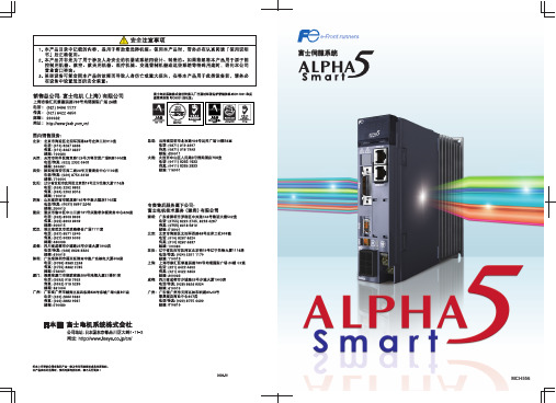
GYG电机 中惯性
GYS电机
3000r/min
最大旋转速度 0.75kW以下:6000r/min 1.0kW以上:5000r/min
GYC电机
3000r/min
最大旋转速度 0.75kW以下:6000r/min 1.0kW以上:5000r/min
GYG电机
2000r/min
最大旋转速度 3000r/min
新自动调谐
对低刚性的装置也可进行最适当的调谐!!
特
长
即使长皮带结构,齿隙大的齿轮或齿条&小齿轮结构,若使用Smart也可轻松调整
至今…
指令速度
若刚性低,将发生 谐振且导致不能提 高响应性。
反馈速度
转矩
而Smart…
指令速度
即使刚性低,也很 难发生谐振、且能 提高响应性,因此 抵抗外紊乱(冲击 负载)性能也很 强。
显示 RYH
【基本型号】 ALPHA5 Smart系列
显示
【功率】
201 20 × 101 = 200W、100W、50W
401
40 × 101 = 400W
751
75 × 101 = 750W、500W
152 15 × 102 = 1.5kW、1.0kW、850W
型
号
说
显示
【系列】
明
F
1500 ~ 3000r/min系列
500
50 × 100 = 0.05kW
101
10 × 101 = 0.1kW
201
20 × 101 = 0.2kW
401 40 × 101 = 0.4kW、0.375kW
501
50 × 101 = 0.5kW
东芝 TS608电话 说明书

兄弟 fax-2820 说明书

按
(复印 ) 键使其变绿。
装入原稿。 使用拨号盘输入要复印的份数 (最多 99 份) 。 按选项键和 ▲ 或 ▼ 键选择 Stack/Sort (堆叠 / 排序) 。 按功能 / 设定键。 按 ▲ 或 ▼ 键选择 Sort (排序) 。 按功能 / 设定键。 按启动键。
v
目录
1
简介
使用本说明书 .......................................................................................................1-1 选择安装位置 .......................................................................................................1-2 如何使用完整的使用说明书 (仅适用于 MFC-7220)..........................................1-3 浏览文档 (适用于 Windows®).....................................................................1-3 如何查找扫描说明 ......................................................................................1-3 浏览文档 (适用于 Macintosh®)...................................................................1-4 如何查找扫描说明 ......................................................................................1-4 控制面板概述 .......................................................................................................1-5 装入原稿 ..............................................................................................................1-7 使用自动进稿器 (ADF) ..................................................................................1-7 关于纸张 ..............................................................................................................1-8 推荐使用的纸张 .............................................................................................1-8 选择适用的纸张 .............................................................................................1-8 纸盒容量 ....................................................................................................1-9 如何装入纸张 ...............................................................................................1-10 将纸张或其他介质装入纸盒 .....................................................................1-10 装入信封 ......................................................................................................1-11 将纸张或其他介质装入手动进纸槽 ...........................................................1-12 有关传真设备 .....................................................................................................1-13 传真音和握手 ...............................................................................................1-13 ECM (错误修正模式)................................................................................1-13 多线连接 (PABX) .........................................................................................1-13
东芝CV330A资料之欧阳总创编

控制柜保险1、保险1F-1 1F-2 1F-3 2F-1 2F-2 2F-4 F-1 F-2 F-3 8F-1 8F-2 8F-3 3FA 3FB●●●●●●●●●●●●●●2、保险说明注:1. ●为走慢车必须安装保险,—为走慢车必须拆除保险。
上述带—保险除3FA、3FB可安装上外,其他保险必须拆除,否则在安装过程中操作不当易造成PU、I/O、及操纵盘基板烧毁。
2.高层及带停电平层的电梯会增加1F-5、2F-5、2F-3等保险安全回路说明1、端子排符号排序PC1C NC NC NC NC P24A P24A P24A P24A NC2….NC2共8个 KNOR R201 T201 NC BKC A2 A7 A10 A11 DC HDC CC DLS2、安全回路封线解析PC1C-A2:机房急停(CCS)、底坑急停两个(1KS1,1KS2)A2-A7:轿顶急停(2KS)、安全钳开关(SOLS)A7-A10:上极限(2LS)、下极限(1LS),轿厢缓冲器开关(BUFS1),对重缓冲器开关(BUFS2),涨绳轮开关(GRS)A10-A11:限速器开关(SLS)A11-HDC:厅门联锁(20+NLS)HDC-DCR:轿门联锁(GLS)走慢车封线1、试运行慢车:①机房打检修②PC1A与A11封③门联锁短封钥匙扳到封闭一侧④CNH1-1(DNLS)、CNH1-2(UPLS)、KNOR与E (地线)短封⑤正确接上码盘线BP5A\BN5A\\PNS\DNS\ZNS⑥接上抱闸线B1,B2⑦插上CNMB插子(抱闸微动开关)CNM12温控开关2、电机线及码盘线接法注:现场安装发现电梯反向的,将U和W调换一下,同时将PNS和DNS调换,方向即改过来了。
一般故障分析1、控制柜继电器排序RLR LZN LBKR SMR 1BKR 2BKR KNORR AMC1 AMC2■■■■■■■■■2、控制柜接触器排序(控制柜左下角)AMC1 AMC2 SC 1BK 1BKX 2BK3、读故障号●●●MOD NUM STB ● PRS①按动最左面〈MOD〉按钮两下,PU基板上显示O.O后面O闪烁②按中间〈NUM〉按钮8下,至显O.8③连续按最后面的〈STB〉按钮,第9下显示出来的数既是故障号④调出故障号后,按动右下角的〈PRS〉按钮一下就恢复原来状态了4、清除故障,解决一般死机状态①按动最左面〈MOD〉按钮两下,PU基板上显示O.O后面O闪烁②按中间〈NUM〉按钮,至显O.E③按右面〈STB〉一下显E1,按〈STB〉一下显OE④按右面〈STB〉一下显E1,按〈NUM〉一下显E2,按〈STB〉一下显OE⑤按右面〈STB〉一下显E1,按〈NUM〉两下显E3,按〈STB〉一下显OE⑥按〈MOD〉按钮一下,清除故障完毕5、故障编码表Ⅰ、故障代码30(STH)检查出暂存器发热异常,电梯停止后SMC跳闸。
AUO_G173HW01_v0_20110530
() Preliminary Specification(V) Final SpecificationModule 17.3” FHD Color TFT-LCD Model Name G173HW01 V0Customer Date Approved byNote: This Specification is subject to change without notice.Checked &Approved by DateVito Huang2011/5/30 Prepared byVivian Huang2011/5/30Audio Video Business Group /AU Optronics corporationContents1. Handling Precautions (4)2. General Description (5)2.1 Display Characteristics (5)3. Functional Block Diagram (10)4. Absolute Maximum Ratings (11)4.1 Absolute Ratings of TFT LCD Module (11)4.2 Absolute Ratings of Environment (11)5. Electrical characteristics (12)5.1 TFT LCD Module (12)5.2 Backlight Unit (14)6. Signal Characteristic (15)6.1 Pixel Format Image (15)6.2 The Input Data Format (16)6.4 Interface Timing (19)6.5 Power ON/OFF Sequence (20)7. Connector & Pin Assignment (21)7.1 TFT LCD Module (21)7.2 Backlight Unit (22)8. Reliability Test (23)9. Shipping Label (24)10. Packing Form (25)10.1 Packaging material (25)10.2 External packaging material required (25)10.3 Palletizing sequence (26)10.4 Packing instruction (27)11. Outline Drawing (28)Record of RevisionVersion & Date PageOld DescriptionNew Description0.0 2011/1/20 All First Edition for Customer0.1 2011/1/31 12 IDD unit: A IDD unit: mA 14 VCC Max: 12.6V VCC Max: 13.4V14 Operation LifeLED life time1.0 2011/5/30 5 White Luminance(cd/m 2): 500(Typ.) White Luminance(cd/m 2): 400(Typ.) 5 Optical Response Time(ms): 8(Typ.)Optical Response Time(ms): 40(Typ.)5 Power Consumption(Watt): TBD(Typ.) Power Consumption(Watt): 17(Typ.) 5 Weight(g): TBD(Typ.) Weight(g): 1080(Typ.)6 Update Viewing Angle 6 Update Optical Response Time6 Update Color / Chromaticity Coordinates6Update White Luminance 12 IDD (mA): 350(Typ), 600(Max) IDD (mA): 1200(Typ), 1400(Max) 12 PDD (Watt): TBD(Typ), 2(Max) PDD (Watt): 5(Typ), 6(Max)12Update the diagram of Vin rising time 14 P VCC (Watt): 11.88(Typ), 13.39(Max) P VCC (Watt): 12(Typ), 15(Max) 14 Update LED Forward Voltage 14 Update Note6 description 25 Update Shipping Label25 Update Packing Form28Update Outline Drawing1. Handling Precautions1) Since front polarizer is easily damaged, please be cautious and not to scratch it.2) Be sure to turn off power supply when inserting or disconnecting from input connector.3) Wipe off water drop immediately. Long contact with water may cause discoloration or spots.4) When the panel surface is soiled, wipe it with absorbent cotton or soft cloth.5) Since the panel is made of glass, it may be broken or cracked if dropped or bumped on hard surface.6) To avoid ESD (Electro Static Discharde) damage, be sure to ground yourself before handling TFT-LCD Module.7) Do not open nor modify the module assembly.8) Do not press the reflector sheet at the back of the module to any direction.9) In case if a module has to be put back into the packing container slot after it was taken out from the container, do not press the center of the LED light bar edge. Instead, pressat the far ends of the LED light bar edge softly. Otherwise the TFT Module may be damaged.10) At the insertion or removal of the Signal Interface Connector, be sure not to rotate nor tilt the Interface Connector of the TFT Module.11) TFT-LCD Module is not allowed to be twisted & bent even force is added on module in a very short time. Please design your display product well to avoid external force applying to module by end-user directly.12) Small amount of materials without flammability grade are used in the TFT-LCD module. The TFT-LCD module should be supplied by power complied with requirements of Limited Power Source (IEC60950 or UL1950), or be applied exemption.13) Severe temperature condition may result in different luminance, response time and lamp ignition voltage.14) Continuous operating TFT-LCD display under low temperature environment may accelerate lamp exhaustion and reduce luminance dramatically.15) The data on this specification sheet is applicable when LCD module is placed in landscape position.16) Continuous displaying fixed pattern may induce image sticking. It’s recommended to use screen saver or shuffle content periodically if fixed pattern is displayed on the screen.2. General DescriptionG173HW01 V0 is a Color Active Matrix Liquid Crystal Display composed of a TFT-LCD panel, a LED driver circuit, and a LED backlight system. The screen format is intended to support the FHD (1920(H) x 1080(V)) screen and 16.7M colors (RGB 6-bits + HiFRC data). All input signals are LVDS interface compatible. Inverter card of backlight is not included.2.1 Display CharacteristicsThe following items are characteristics summary on the table under 25 ℃condition:Items Unit Specifications Screen Diagonal [mm] 17.3W (17.25)Active Area [mm] 381.888 (H) x 214.812 (V)Pixels H x V 1920(x3) x 1080Pixel Pitch [mm] 0.1989 (per one triad) x 0.1989Pixel Arrangement R.G.B. Vertical StripeDisplay Mode Normally WhiteWhite Luminance [cd/m2] 400 (Typ.)Contrast Ratio 600 : 1 (Typ)Optical ResponseTime [msec] 40 (Typ, on/off)Nominal Input Voltage VDD [Volt] 3.3 VPower Consumption [Watt] 17 (Typ)Weight [Grams] 1080 (Typ)Physical Size (H x V x D) [mm] 403 (H) x 240 (V) x 12.5 (D) (Typ) Electrical Interface Dual channel LVDSSurface Treatment Hard-coating (3H), Glare treatment Support Color 16.7M colors (RGB 6-bit data + HiFRC data)Temperature Range (Ta) Operating Storage (Non-Operating) [o C][o C]0 to +70-20 to +70RoHS Compliance RoHS Compliance2.2 Optical CharacteristicsThe optical characteristics are measured under stable conditions at 25℃ (Room Temperature):ItemUnit Conditions Min.Typ.Max.NoteHorizontal (Right) CR = 10 (Left) 70 70 80 80 -Viewing Angle [degree]Vertical (Up) CR = 10 (Down) 50 70 60 80 - 1Luminance Uniformity [%] 13 Points 75 80 - 2, 3Rising - 37 50 Falling - 3 10 Optical Response Time[msec] Rising + Falling -4060 4, 5 Red x 0.590 0.640 0.690 Red y 0.296 0.346 0.396 Green x 0.264 0.314 0.364 Green y 0.574 0.624 0.674 Blue x 0.100 0.150 0.200 Blue y 0.004 0.054 0.104 White x 0.255 0.305 0.355 Color / Chromaticity Coordinates (CIE 1931)White y0.268 0.318 0.368 4 White Luminance (At LED=100mA) [cd/m2 ]320 400 - 4 Contrast Ratio 500 600 - 4 NTSC%72Optical Equipment: BM-5A, BM-7, PR880, or equivalentNote 1: Definition of viewing angleViewing angle is the measurement of contrast ratio≧10, or ≧5, at the screen center, over a 180° horizontal and 180° vertical range (off-normal viewing angles). The 180° viewing angle range is broken down as follows; 90° (θ) horizontal left and right and 90° (Φ) vertical, high (up) and low (down). The measurement direction is typically perpendicular to the display surface with the screen rotated about its center to develop the desired measurement viewing angle.Note 2: 13 points positionNote 3:Note 4: Measurement methodThe LCD module should be stabilized at given temperature for 30 minutes to avoid abrupt temperature change during measuring. In order to stabilize the luminance, the measurement should be executed after lighting Backlight for 30 minutes in a stable, windless and dark room.Note 5: Definition of response time:The output signals of photo detector are measured when the input signals are changed from “Full Black” to “Full White” (rising time), and from “Full White” to “Full Black” (falling time), respectively. The response time is interval between the 10% and 90% of amplitudes. Please refer to the figure as below.3. Functional Block DiagramThe following diagram shows the functional block of the 17.3 inches Color TFT-LCD Module:4. Absolute Maximum RatingsAbsolute maximum ratings of the module are as following:4.1 Absolute Ratings of TFT LCD ModuleItem Symbol Min Max Unit Logic/LCD Drive Voltage Vin -0.3 +3.6 [Volt]4.2 Absolute Ratings of EnvironmentItem Symbol Min Max Unit Operating Temperature TOP 0 +70 [o C] Operation Humidity HOP 5 95 [%RH] Storage Temperature TST -20 +70 [o C] Storage Humidity HST 5 95 [%RH] Note: Maximum Wet- and no condensation.5. Electrical characteristics 5.1 TFT LCD Module5.1.1 Power Specification Input power specifications are as follows:SymbleParameter Min.Typ.Max.UnitConditionVDD Logic/LCD DriveVoltage 3.0 3.3 3.6 [Volt] ±10%IDD Input Current - 1200 1400 [mA] VDD= 5.0V, All Black Pattern At 75Hz, +30%PDD VDD Power - 5 6 [Watt] VDD= 5.0V, All Black Pattern At 75Hz , Note 1IRush Inrush Current- - 2000 [A] Note 2VDDrpAllowable Logic/LCD Drive Ripple Voltage --100[mV] p-pVDD= 3.3V, All Black Pattern At 75HzNote 1: The variance of VDD power consumption is ±30%. Note 2: Measurement conditions:Vin rising time0V5.1.2 Signal Electrical Characteristics Input signals shall be low or Hi-Z state when VDD is off. Note: LVDS Signal Waveform.5.2 Backlight UnitFollowing characteristics are measured under a stable condition using a inverter at 25℃. (Room Temperature): Symbol Parameter Min.Typ.Max.Unit RemarkVCC Input Voltage 10.8 12 13.4 [Volt]I VCC Input Current - 0.99 - [A] 100% PWM DutyP VCC Power Consumption - 12 15 [Watt]100% PWM DutyF PWM Dimming Frequency 200 - 20K [Hz]Swing Voltage 3 3.3 5.5 [Volt]Dimming duty cycle 5 - 100 %I F LED Forward Current-100 -[mA] Ta = 25o C- (3.3) (3.7) [Volt]I F = 100mA, Ta = 0o C- 3.2 3.6 [Volt]I F = 100mA, Ta = 25o C V F LED Forward Voltage- (3.1) (3.5) [Volt]I F = 100mA, Ta = 70o C P LED LED Power Consumption- (10.24)11.52 [Watt]LED Life Time50,000 - - Hrs I F=100mA, Ta= 25o CNote 1: Ta means ambient temperature of TFT-LCD module.Note 2: VCC, I VCC, P VCC are defined for LED backlight.(100% duty of PWM dimming)Note 3: I F, V F are defined for one channel LED. There are four LED channel in back light unit.Note 4: If G173HW01 V0 module is driven by high current or at high ambient temperature & humidity condition. The operating life will be reduced.Note 5: Operating life means brightness goes down to 50% initial brightness. Minimum operating life time is estimated data.Note 6: LED lifetime is definition: brightness is decreased to 50% of the initial value. LED lifetime is restricted under6. Signal Characteristic6.1 Pixel Format ImageFollowing figure shows the relationship of the input signals and LCD pixel format.1st2nd1919th1920th1stLine1080thLin6.2 The Input Data FormatNote1: Normally, DE, VS, HS on EVEN channel are not used. Note2: 8-bit in6.3 Signal DescriptionThe module using a pair of LVDS receiver SN75LVDS82(Texas Instruments) or compatible. LVDS is a differential signal technology for LCD interface and high speed data transfer device. Transmitter shall be SN75LVDS83(negative edge sampling) or compatible. The first LVDS port(RxOxxx) transmits odd pixels while the second LVDS port(RxExxx) transmits even pixels.PIN #SIGNAL NAME DESCRIPTION1 RxOIN0- Negative LVDS differential data input (Odd data)2 RxOIN0+ Positive LVDS differential data input (Odd data)3 RxOIN1- Negative LVDS differential data input (Odd data)4 RxOIN1+ Positive LVDS differential data input (Odd data)5 RxOIN2- Negative LVDS differential data input (Odd data, H-Sync,V-Sync,DSPTMG)6 RxOIN2+ Positive LVDS differential data input (Odd data, H-Sync,V-Sync,DSPTMG)7 VSS Power Ground8 RxOCLKIN- Negative LVDS differential clock input (Odd clock)9 RxOCLKIN+Positive LVDS differential clock input (Odd clock)10 RxOIN3- Negative LVDS differential data input (Odd data)11 RxOIN3+ Positive LVDS differential data input (Odd data)12 RxEIN0- Negative LVDS differential data input (Even data)13 RxEIN0+ Positive LVDS differential data input (Even data)14 VSS Power Ground15 RxEIN1- Negative LVDS differential data input (Even data)16 RxEIN1+ Positive LVDS differential data input (Even data)17 VSS Power Ground18 RxEIN2- Negative LVDS differential data input (Even data)19 RxEIN2+ Positive LVDS differential data input (Even data)20 RxECLKIN- Negative LVDS differential clock input (Even clock)21 RxECLKIN+ Positive LVDS differential clock input (Even clock)22 RxEIN3- Negative LVDS differential data input (Even data)23 RxEIN3+ Positive LVDS differential data input (Even data)24 VSS Power Ground25 VSS Power Ground26 VSS Power Ground27 VSS Power Ground28 VDD +3.3V Power Supply29 VDD +3.3V Power Supply30 VDD +3.3V Power SupplyNote1: Start from left sideRxOIN0-VDDNote2: Input signals of odd and even clock shall be the same timing. Note3: Please follow PSWG.6.4 Interface Timing6.4.1 Timing CharacteristicsBasically, interface timings should match the 1920X1080 / 60Hz manufacturing guide line timing.Note : DE mode only6.4.2 Timing Diagram6.5 Power ON/OFF SequenceVDD power and lamp on/off sequence is as follows. Interface signals are also shown in the chart. Signals from any system shall be Hi-Z state or low level when VDD is off.Power Sequence TimingPower Sequence TimingValueUnitsParameterMin. Typ. Max.T1 0.5 - 10T2 0 - 50T3 200 - --T4 0.5 - 10T5 10 - -T6 10 - -msT7 0 - -T8 10 - -T9 - - 10T10 110 - -T11 0 50T12 0 10T13 500 - -7. Connector & Pin AssignmentPhysical interface is described as for the connector on module.These connectors are capable of accommodating the following signals and will be following components.7.1 TFT LCD Module7.1.1 ConnectorConnector Name / Designation Interface Connector / Interface card Manufacturer HRSType Part Number MDF76TW-30S-1HMating Type Part Number MDF76-30P-1C7.1.2 Pin AssignmentPin#Signal Name Pin#Signal Name1 RxOIN0-2 RxOIN0+3 RxOIN1-4 RxOIN1+5 RxOIN2-6 RxOIN2+7 VSS 8 RxOCLKIN-9 RxOCLKIN+ 10 RxOIN3-11 RxOIN3+ 12 RxEIN0-13 RxEIN0+ 14 VSS15 RxEIN1- 16 RxEIN1+17 VSS 18 RxEIN2-19 RxEIN2+ 20 RxECLKIN-21 RxECLKIN+ 22 RxEIN3-23 RxEIN3+ 24 VSS25 VSS 26 VSS27 VSS 28 VDD29 VDD 30 VDD7.2 Backlight UnitPhysical interface is described as for the connector on module. These connectors are capable of accommodating the following signals and will be following components.7.2.1 ConnectorConnector Name / Designation Lamp Connector / Backlight lamp Manufacturer HRSType Part Number DF14A-6P-1.25HMating Type Part Number DF14-6S-1.25C7.2.2 Pin AssignmentPin No. Symbol DescriptionPin1 VLED 12V inputPin2 VLED 12V inputPin3 GND GNDPin4 GND GNDPin5 On/OFF 3.3-5V:ON, 0V:OFFPin6 Dimming PWM8. Reliability TestEnvironment test conditions are listed as following table.Items Required Condition Note Temperature Humidity Bias (THB) Ta= 50℃, 80%RH, 240hoursHigh Temperature Operation (HTO)Ta= 70℃, 240hoursLow Temperature Operation (LTO) Ta= 0℃, 240hoursHigh Temperature Storage (HTS) Ta= 70℃, 240hoursLow Temperature Storage (LTS) Ta= -20℃, 240hoursVibration Test (Non-operation) Acceleration: 1.5 GWave: Random Frequency: 10 - 200 - 10 Hz Sweep: 30 Minutes each Axis (X, Y, Z)Shock Test (Non-operation) Acceleration: 50 GWave: Half-sineActive Time: 20 msDirection: ±X,±Y,±Z (one time for each Axis)Drop Test Height: 60 cm, package testThermal Shock Test (TST) -20℃/30min, 60℃/30min, 50 cycles 1Contact Discharge: ± 8KV, 150pF(330Ω ) 1sec,8 points, 25 times/ point.ESD (Electro-Static Discharge)Air Discharge: ± 15KV, 150pF(330Ω ) 1sec8 points, 25 times/ point.2Note 1: The TFT-LCD module will not sustain damage after being subjected to 100 cycles of rapid temperature change. A cycle of rapid temperature change consists of varying the temperature from -20℃to 60℃, and back again. Power is not applied during the test. After temperature cycling, the unit is placed in normal room ambient for at least 4 hours before power on.Note 2: According to EN61000-4-2, ESD class B: Some performance degradation allowed. No data lost.Self-recoverable. No hardware failures.9. Shipping LabelUnit: mm10. Packing Form10.1 Packaging materialFILM PROTECTBAG ANTI-STATICTAPETAPE CREPED PAPERPACKING CARTONLABEL SPECLABEL CARTON.CUSHION PACKING10.2 External packaging material required‧Carton : 524mm*321mm*360mm, weight (carton + cushion): 1250g‧Pallet : 1140mm*980mm*140mm‧Stretch film : 500mm (W)*300M (L)‧Corner angle : L type fiber board‧PET band : 19mm (W)‧ Label : 220mm*200mm10.3 Palletizing sequencepcs / box box / layer layer / pallet pcs / pallet Shipping by air 10 2*3 3 180 Shipping by sea 10 2*3 3 180A U O P T R O N I C S C O R P O R A T I O NP r o d u c t S p e c i f i c a t i o nm e n t v e r s i o n 1.0 27/29G 173H W 01 V 0P a c k i n g i n s t r u c t i o nA U O P T R O N I C S C O R P O R A T I O NP r o d u c t S p e c i f i c a t i o nm e n t v e r s i o n 1.0 28/29G 173H W 01 V 0A U O P T R O N I C S C O R P O R A T I O NP r o d u c t S p e c i f i c a t i o nm e n t v e r s i o n 1.0 29/29G 173H W 01 V 0。
东芝cv320a故障码调阅及故障代码
VF3系列故障码调阅流程总则:为了提高故障处理效率,特别制作本流程教材。
一、代号命名约定。
基板按钮位置命名,如下图所示后面的操作均以下图所示标识代号为准。
注意事项:1、请对图操作,如不一样,请勿操作。
2、严禁未授权人员操作,操作人员请严格按照步骤流程说明进行操作。
3、操作时候请适当出力,以免损坏基板。
二、调阅流程1、PUS故障第一条故障:设定内容及步骤含义:调阅第一条PUS的故障,读取 4000:0007 000a 000b 的数据调阅步骤a.故障码K开关拨到S,按D两次进行复位。
按A 2次,3号灯亮起,显示“00”按C 2次,按B 4次,按C 4次,交替显示“4000”后显示回“00”。
按B 1次,按C 6次,显示成“01”按B 2次,显示成“03”,按C 3次,显示“00”按B 7次,显示“07”,按C 1次,显示的数据即为故障码,将其记录入表格。
b.数据3调阅按D两次进行复位按A 2次,3号灯亮起,显示“00”按B 3次,显示“03”,按C 3次,显示“00”按B 10次,显示“0A”,按C 1次,显示的数据即为数据3的代码,将其记录如表格。
c.数据4调阅按D两次进行复位按A 2次,3号灯亮起,显示“00”按B 3次,显示“03”,按C 3次,显示“00”按B 11次,显示“0b”,按C 1次,显示的数据即为数据4的代码,将其记录入表格。
第二条故障:设定内容及步骤含义:调阅第二条PUS的故障,读取4000:0017 001a 001b 的数据。
调阅步骤a.故障码按D两次进行复位按A 2次,3号灯亮起,显示“00”按B 3次,显示“03”,按C 2次,显示“00”按B 1次,显示“10”,按C 1次,按B 7次,显示“17”按C 1次即可得到第二条故障码,将其记录入表格。
(如果此时调阅出的故障代码是“00”则以下的步骤可以省略,直接转到PUM故障调阅。
)b.数据3调阅按D两次复位。
按B 3次,显示“03”,按C 2次,显示“00”按B 1次,显示“10”,按C 1次,按B 10次,显示“1A”按C 1次即可得到第二条故障代码的数据3,将其记录入表格。
MOTOVARIO摩多利马达
MOTOVARIO摩多利马达/刹车马达 T/TB/S全系列的电机都配备散热装置,整机为铝合金或铸铝外壳,绝缘等级为F级,防护等级为IP55级,机座号从63到132,功率为0.09KW到11KW.型号说明: T系列-----三相交流电机D系列-----双速三相交流电机S系列-----单相电机TB系列----刹车三相交流电机DB系列----杀车双速三相交流电机SB系列----刹车单相电机HS系列----单相高启动扭矩马达加离心开关MOTOVARIO摩多利轴装式齿轮减速机 CS有五种大小型号功率从0.12千瓦到22千瓦加硬处理的钢齿轮减速比从7.3到360全部外壳材料为铸铁提供两级和三级减速外壳全部涂上Ral 5010深蓝环氧树脂漆油MOTOVARIO摩多利斜伞齿轮减速机 CB/CBA有八种大小型号功率从0.12千瓦到45千瓦(铝合金只到4.8千瓦)减速比从2到350型号070以下为铝合金外壳(BA),080开始为铸铁外壳(H)提供单级,两级和三级减速铝合金外壳即有轻盈的特点也不失牢固的优势外壳全部涂上RAL 5010深蓝环氧树脂漆油摩多利斜齿轮减速机 CH/CHA系列有八种大小型号功率从0.12千瓦到45千瓦加硬处理的钢斜齿轮伞齿轮材料为铜合金减速比从2到280全部外壳材料为铸铁和铝合金提供两级和三级减速最牢固的机械设计外壳全部皆涂上Ral 5010深蓝环氧树脂漆油无段变速减速机 SF/ST/FX共有7种型号,功率从0.15KW到9.2KW变速范围:速比I=3.5(型号:005/080 至010-090)速比I=6(型号:005-010)速比I=5(涵盖每个型号)嗓音低,运转时无震动高效率,可双向旋转可以根据需要在电机的两边安装调速手轮速度误差(最大):±0.5%速度误差(最小):±0.1%调节灵敏度:0.5rpm外壳材质(TK-VK-PK-SK):G200灰铸铁(IS0185)外壳材质(TX):铝合金轴材质:合金钢20MnCr5(UNI8550)内部元件:100Cr6 热处理钢外壳全部涂上Ral 5010深蓝色环氧树脂漆油外壳全部皆涂上Ral 5010深蓝色环氧树脂漆油摩多利蜗轮蜗杆减速机 NMRV有十一种大小型号功率从0.06千瓦到15千瓦拥有专利的铝合金外壳先进设计,轻便牢固能提供灵活多样的安装方式单级减速比从5到100,可两台搭配以达到更高速比型号105以下为铸钻外壳,110开始为铸铁外壳蜗杆材料:热加工硬化 20Mrcr5 不锈钢(UNI 8550)蜗轮材料:青铜GCu Sn12(UNI7013-72)铝合金外壳即有轻盈的特点也不失牢固的优势型号030以上的外壳全部涂上Ral 5010深蓝环氧树脂漆油松下电机三相感应马达1、三相电动机是在三相电源时使用的感应电动机2、额定时间连续3、(日本)国内规格的电动机采用的耐热等级为120(E)。
西门子 3VF 样本 低压控制产品与系统 说明书
s装置3VF 样本3VF Catalog分解图1 Exploded drawing描述2 Descriptions选型和订货参数Selection and ordering data线路保护型断路器Circuit-Breakers for Plant Protection3VF2 断路器,3极和4极,至100A, I cu至18kA7 3VF2 circuit-breakers, 3- and 4-pole, up to 100 A, Iup to 18kAcu3VF3 断路器,3极和4极,至160A, I cu至25kA9 3VF3 circuit-breakers, 3- and 4-pole, up to 160A, Iup to 25kAcu3VF3至3VF8断路器,3极,至2500A10 3VF3 to 3FV8 circuit-breakers, 3-pole, up to 2500A3VF3至3VF8断路器,4极,至2500A16 3VF3 to 3FV8 circuit-breakers, 4- pole, up to 2500A电动机保护型断路器Circuit-Breakers for Motor Protection3VF3、3VF5和3VF6断路器,3极,至500A14 3VF3, 3VF5 and 3VF6 circuit-breakers, 3-pole, up to 500A起动器组合用断路器Circuit-Breakers for Starter Combinations3VF3至3VF6断路器,3极,至500A14 3VF3 to 3VF6 circuit-breakers, 3-pole, up to 500A隔离型断路器Switch disconnector with short-circuit protection3VF3至3VF8断路器,3极,至2000A14 3VF3 to 3VF8 non-automatic circuit-breakers, 3-pole, up to 2000A3VF3至3VF8断路器,4极,至2000A20 3VF3 to 3VF8 non-automatic circuit-breakers, 4-pole, up to 2000A其他规格,附件和备件Further items, accessories and spare parts用于改装的附件-辅助开关和报警开关24 Accessories for retrofitting - Auxiliary and alarm switches用于改装的附件-分励脱扣器和欠压脱扣器26 Accessories for retrofitting - Shunt trips and Undervoltage releases附件-操作机构28 Accessories - Drive Mechanisms附件-连接件32 Accessories - Connections附件-锁具,罩盖36 Accessories - Locking devices, covers带DI模块的3VF3至3VF5断路器38 3VF3 to 3VF5 Circuit-breakers with DI Module技术参数40 Technical data特性曲线48 Characteristic curves线路示意图55 Circuit diagrams尺寸59 Dimensions附件-连接件Accessories - Connections相间隔板Interphase barrier主回路端子罩盖Terminal cover for main terminals 正面母排连接件Front busbar connection pieces用于3VF3的背后连接件Rear terminal for 3VF3用于3VF7的背后连接件Rear terminal for 3VF7多路进线端子Multiple feed-in terminal插入式安装底板Plug-in socket 附件-防护门框Accessories - Covers8断路器柜门开孔防护框Covering frame for door cutout附件-操作机构Accessories - Operating mechanisms9用于3VF3的电动机操作机构Motorized operating mechanism for 3VF310用于3VF4、3VF5、3VF6的旋转驱动机构Rotary drive for 3VF4, 3VF5, 3VF611柜门耦合旋转驱动机构,整套Rotary drive, complete for fitting in doorsand covers (with door coupling rotarymechanism)12DI模块DI module附件-辅助开关Accessories - Auxiliary Switches13辅助开关和报警开关,带连接线Auxiliary and alarm switchVersion with connecting leads14辅助开关和报警开关,带接线端子盒Auxiliary and alarm switchVersion with box terminals3VF3至3VF7断路器,3极和4极,至1250A 3VF3 to 3VF7 Circuit-Breakers, 3 and 4-pole, up to 1250A12标准所有3VF 断路器都符合IEC60947-1/DIN VDE0660,第100部分;IEC60947-2/DIN VDE0660,第101部分之标准。