plastic bottle catia 的可乐瓶练习
饮料瓶的三维结构设计
华中科技大学文华学院毕业设计(论文)饮料瓶的三维结构设计学生姓名:徐某某学号:********** 学部(系):机械与电气工程学部专业年级: 09机械设计制造与制造指导教师:韩某某职称或学位:讲师2012年 5 月 20 日目录摘要 (I)关键词 (I)Abstract ......................................................................................................................................................... I I Key words ...................................................................................................................................................... I I 1绪论 .. (1)1.1Pro/e的发展前景 (1)1.2设计饮料瓶的目的和意义 (3)2 三维造型设计 (5)2.1设计饮料瓶的方法比较以及遇到的难点 (5)2.1.1学Pro/e需要的基础 (5)2.2 设计过程 (9)2.2.1饮料瓶设计 (9)2.3 本节小结 (13)3 二维工程图的创建 (14)3.1 设计概述 (14)3.2 设计流程 (14)3.3 本节小结 (15)结论 (16)参考文献 (17)致谢 (18)饮料瓶的三维结构设计摘要本次三维设计使用的是PROE软件,PRO/E作为全世界最普及的3D CAD/CAM系统.被广泛应用于电子、机械、模具、工业设计、汽车、机车、自行车、航天、家电、玩具等各行业。
本文利用PROE进行饮料瓶的三维结构设计,这个模型必须使用曲面造型才能完成设计任务,在日常的模具产品设计中,曲面设计也是必不可少的。
CAXA制造工程师习题(塑料瓶底画法)

-第13章 综合实例13.1可乐瓶底的造型和加工13.1.1 凹模型腔的造型13.1.1.1造型方法分析可乐瓶底的表面主要由曲面构成,造型比较复杂。
由于直接用实体造型不能完成,所以先利用CAXA 制造工程师强大的曲面造型功能做出曲面,再利用曲面裁剪除料生成凹模型腔。
可乐瓶底的侧表面可以用网格面来生成,因为是由图6-30可乐瓶底曲面造型的二维图图6-29可乐瓶底曲面造型和凹模型腔造型五个完全相同的部分组成的,我们只要作出一个突起的两根截面线和一个凹进的一根截面线,然后进行环形阵列就可以得到其他几个突起和凹进的所有截面线,最后使用网格面功能生成曲面。
可乐瓶底的最下面的平面我们使用直纹面中的--“点+曲线”方式来做,这样做的好处是在做加工时两张面(直纹面和网格面)可以一同用参数线加工。
最后以瓶底的上口为准,构造一个立方体实体,然后用可乐瓶底的两张面把不需要的部分裁剪掉,就可以得到我们要求的凹模型腔。
13.2.1.2绘制截面线1.按下“F7”键将绘图平面切换到XOZ 平面。
2.单击“矩形”按钮,在立即菜单中选择“中心_长_宽”方式,输入长度42.5,宽度37,输入(21.25,0,-18.5)为中心点,绘制一个42.5×37的矩形。
如图6-31所示 3.单击“等距线”按钮,在立即菜单中输入距离3,拾取矩形的最上面一条边,选择向下箭头为等距方向,生成距离为3的等距线。
相同的等距方法,生成如图所示尺寸标注的各个等距线,如图6-32所示。
4.单击“裁剪”按钮,拾取需要裁剪的线段,然后单击“删除”按钮,拾取需要删除的直线,按右键确认删除,结果如图6-33所示。
5. 作过P1、P2点且与直线L1相切的圆弧。
单击 “圆弧图6-31矩形图6-32等距线图6-33 删除结果-”按钮,选择“两点_半径”方式,拾取P1点和P2点,然后按空格键在弹出的点工具菜单中选择“切点”命令,拾取直线L1。
6.作过P4点且与直线L2相切,半径为6的圆R6。
CATIA实操瓶子的设计方法
CATIA实操瓶子的设计方法在工业设计领域,CATIA 是一款功能强大的软件,能够帮助设计师实现各种复杂的设计构想。
今天,我们就来详细探讨一下如何使用CATIA 来设计一个瓶子。
首先,打开 CATIA 软件,新建一个零件文件。
在开始设计之前,我们需要明确瓶子的设计要求,比如瓶子的用途(是用于盛装液体还是固体)、容量大小、外观风格(简约、时尚、复古等)、材质(玻璃、塑料、金属等)以及生产工艺(吹塑、注塑、压铸等)。
假设我们要设计一个用于盛装饮料的塑料瓶,容量为 500 毫升,外观简约时尚。
第一步,绘制瓶子的轮廓草图。
选择“草图”工具,在基准平面上绘制瓶子的大致轮廓。
可以先画出一个长方形,作为瓶子的主体部分,然后在长方形的上方和下方分别绘制出弧形,以形成瓶颈和瓶底的初步形状。
注意,在绘制草图时,要合理使用约束工具,确保线条之间的位置和尺寸关系准确无误。
第二步,对草图进行拉伸操作。
选中绘制好的草图,选择“拉伸”工具,输入合适的拉伸长度,从而得到瓶子的初步实体模型。
接下来,对瓶子的瓶颈部分进行细化设计。
再次进入草图模式,在瓶颈处绘制新的草图,如螺纹或者防滑纹理等。
完成草图后,进行相应的特征操作,如旋转、扫掠等,以实现所需的效果。
瓶底的设计也不容忽视。
同样通过草图和特征操作,为瓶底设计出合适的形状,比如平底、凹底或者凸底,并考虑其稳定性和受力情况。
在设计过程中,要时刻关注瓶子的整体比例和对称性。
可以使用CATIA 中的“测量”工具,测量瓶子各部分的尺寸和角度,确保符合设计要求。
然后,对瓶子的表面进行处理。
如果想要瓶子表面呈现出光滑的效果,可以使用“曲面拟合”工具;如果希望有磨砂质感,则可以通过添加纹理或使用“布尔运算”来实现。
此外,还可以为瓶子添加一些装饰元素,如品牌标志、图案等。
这可以通过在瓶身表面绘制草图,然后进行浮雕或刻蚀等操作来完成。
当瓶子的主体设计完成后,不要忘记对其进行装配检查。
将瓶子放入虚拟的包装环境中,查看其与其他部件的配合是否良好,是否存在干涉等问题。
Catia曲面设计的流程
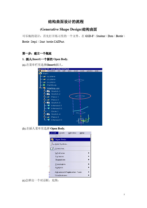
结构曲面设计的流程(Generative Shape Design)结构曲面可乐瓶的设计:首先打开练习里的一个文件,在GSD-F \ Student \ Data \ Bottle \ Bottle_Step1 \ Start_bottle.CA TPart.第一步:建立一个瓶底1. 插人(Insert)一个新的Open Body.(a).在菜单栏里选择(Insert)插人。
(b).在插人菜单里选择Open Body.(c)会弹出一个对话框,见图:2.在结构树上点击Open Body,用右键弹出菜单选择属性(Properties),见图3.选择(Feature Properties),把Open Body改成Bottle_Bottom_a 。
见图:4.建立一个交点( Intersection )(a)选择交点(Intersection)图标。
见图(b)在(first elemen)对话框里选择Sketch.2。
(c)在(second element)对话框里选择Intersect.1。
见图点击ok5.建立一个圆弧:(a)选择Work on Support的图标,见图:(b)选择zx平面作为基准面点击ok(c)选择(Circle )这个图标。
(d) 在(Circle type)里,选择“Center and Point”见图:(c)在(Center)复选框里,用右键弹出菜单,并且选择(Create Point)见图:(d)在这个点的复选框里,选择所需要的参数。
见图:(参考基准点)ReferenceÆPoint复选框里的(Intersect.4),在结构树上点击。
点击ok(c) 圆的中心点被建立了,在(point)复选框里,选择(Intersect.4), 在(Start)复选框里, 选择-90deg, (End)复选框里, 选择90deg。
见图点击ok6.建立二根相切的直线:(a)选择点(Point)的图标:点的参数见图:(b)选择对称(Symmetry)的图标:(c)在元素(Element)复选框里,选择(Point.2), 对称参考轴(Reference)复选框里,选择(Intersect.1), 见图:点击ok7.双击线(Line)的图标:(a)在线的类型里(line type), 选择(Tangent to Curve), 见图:(b)在(Curve)的复选框里,选择(Circle.2), (Element.2)的复选框里,选择(Point.2),相切选项里(Tangency options), 选择(BiTangent). 见图:点击ok(c)重复(b)的操作的方法,做另一个对称的线。
CATIA曲面练习之饮料瓶建模
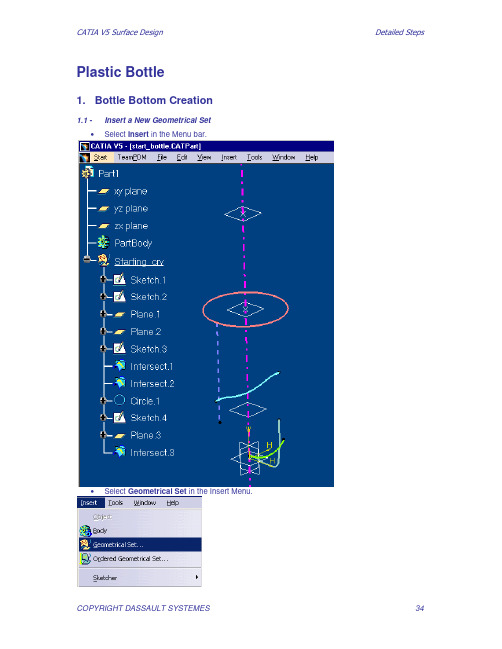
1. Bottle Bottom Creation
1.1 • Insert a New Geometrical Set Select Insert in the Menu bar.
•
Select Geometrical Set in the Insert Menu.
COPYRIGHT DASSAULT SYSTEMES
COPYRIGHT DASSAULT SYSTEMES
51
•
Redo the same operation with the Plane Symmetry.2
•
Click on OK to confirm the Split creation. 52
COPYRIGHT DASSAULT SYSTEMES
COPYRIGHT DASSAULT SYSTEMES
50
•
Click on OK to confirm the fillet creation.
1.15 •
Create the complete bottom. Select the Split icon then the EdgeFillet.1 you have just created and the Plane.4 and keep the side as shown.
• •
Click OK. Select the Circle icon.
•
Choose ‘’Center and Point’’ as Circle type.
•
Open a contextual menu in the Center field and choose Create Point 37
catia逆向建模范例(油壶)
CATIA Training Q u i c k S u r f a c eR e c o n s t r u c t i o nD e t a i l e d S t e p sTable of ContentsPlastic bottle exercise (3)Step (1): Scans creation (3)Step (2): Curves creation (5)Step (3): Surfaces creation (10)Step (4): Creating the rough model (18)Step (5): Filleting the model (21)Plastic bottle exerciseStep (1): Scans creationLoad the file exercise_start.CATPart from the indicated directory. Start the Quick Surface Reconstruction workbench.1. Create a first scan at the symmetry plane:a. Click on the Planar sections iconb. Select the tessellationc. Click on the Flip to XZ buttond. Activate the contextual menu of the plane manipulatore. Select the Edit optionf. Set the Y coordinates to 0g. Click the Close buttonh. Check the Grouped into one element optioni. Click on the Apply buttonj. Click on the OK button2. Create a second scan by isoslope computation:a. Click on the Slope analysis iconb. Select the tesselationc. Click on the Flip to X buttond. Set the Filter value to 250e. Check the Distinct optionf. Click on the OK button3. Create a third scan by planar section:a. Click on the Planar sections iconb. Select the tessellationc. Click on the Flip to XY buttond. Activate the contextual menu of the plane manipulatore. Select the Edit optionf. Set the Z coordinates to 205g. Click the Close buttonh. Check the Distinct optioni. Click on the Apply buttonj. Click on the OK button4. Create a last scan by planar sections:a. Click on the Planar sections iconb. Select the tessellationc. Click on the Flip to XY buttond. Activate the contextual menu of the plane manipulatore. Select the Edit optionf. Set the Z coordinates to 0g. Click the Close buttonh. Check the Distinct optioni. Click on the Apply buttonj. Click on the OK buttonStep (2): Curves creationBefore starting the curves creation, create a new open body and name it Curves creation.You can also load the file End_step1.CATPart from the indicated directory1. Create curves from the scan on the symmetry planea. Click on the Curve from scan iconb. Select the first created scanc. Set the Accuracy value to 0.5d. Set the Degree value to 6e. Set the Number value to 20f. Activate the Smoothing creation modeg. Set the Split angle value to 45h. Add two splitting points below the top fillet and before the handle fillet with point continuityi. Add one splitting point below the fillet handle with point continuityj. Add 4 splitting point at the bottom of the bottle with Tangent continuityk. Add one splitting point below the fillet handle with point continuityl. Add 2 splitting points as shown with point continuityTotal splitting points should look like this:m. Click on the Apply buttonn. Click on the OK button2. Create a curve from the second scana. Click on the Curve from scan iconb. Select the scan created by isoslopec. Set the Split Angle value to 90d. Remove all the splitting points using the Remove split option of the contextual menu of eachpointe. Remove both extremities using the Remove split option of the contextual menu of eachextremityf. Add one splitting point on the scan below the top fillet and before the top intersection scang. Add one splitting point on the scan below the bottom intersection scanh. Set the accuracy value to 1mmi. Set the Order value to 4j. Click on the Apply buttonk. Click on the OK button3. Create a curve on the top scana. Click on the Curve from scan iconb. Select the third scan createdc. Set the Accuracy value to 0.5mmd. Click on the Apply buttone. Click on the OK button4. Create a curve on the last scana. Click on the Curve from scan iconb. Select the last scan createdc. Add splitting points with tangent continuity as shownd. Click on the Apply buttone. Click on the OK button5. Hide all the scans6. Trim all the curves createda. Click on the Curves slice iconb. Select all the curves using a trapc. Click on the More buttond. Set the Max distance to 2mme. Click on the Apply button to preview the intersecting pointsf. Click on the OK button7. Delete the two curves in the handle:8. Start the Wireframe and Surface design workbench9. Create a blending curve in the left handle areaa. Click on the Connect curves iconb. Select the extremity point of the top curvec. Select the extremity point of the bottom curved. Reverse the blending direction if necessarye. Click on the OK button10. Create a blending curve in the right handle areaa. Click on the Connect curves iconb. Select the extremity point of the top curvec. Select the extremity point of the bottom curved. Reverse the blending direction if necessarye. Click on the OK buttonStep (3): Surfaces creationBefore starting the surfaces creation, create a new open body and name it Surfaces creation. You can also load the file End_step2.CATPart from the indicated directory.1. Create extruded surfaces to be used as tangency constraints:a. Click on the Extrude iconb. Select a curve in the symmetry planec. Set the Direction to Y axisd. Set the extrusion Limit 1 to 20mme. Reverse the extrusion direction if necessaryf. Click on the OK buttong. Repeat the actions a. to f. for all the curves in the symmetry plane:2. Extrude the middle curve to create a tangency constraint:a. Click on the Extrude iconb. Select the middle curve resulting from the smoothing of the isoslope scanc. Set the Direction to X axisd. Set the extrusion Limit 1 to 20mme. Reverse the extrusion direction if necessaryf. Click on the OK button3. Hide the extruded curves4. Start the Quick Surface Reconstruction workbench5. Activate the points of the left half of the bottle:a. Click on the Activate iconb. Activate the Trap optionc. Activate the Polygonal optiond. Activate the Inside trap optione. Select the tessellationf. Define a trap around the points of the left side of the bottle, excluding the handle pointsg. Click on the OK button6. Create a first surface on these points:a. Click on the Power fit iconb. Set the Point gap value to 0.5mmc. Select the tessellationd. Select the 7 boundary curves for the area to fillKeep the default continuity level for all curvese. Click on the Apply buttonf. Click on the OK button7. Hide the middle symmetry constraint surface8. Activate the points of right half of the tessellation:a. Click on the Activate iconb. Select the tessellationc. Click on the Activate all buttond. Define a trap around the points of the right side of the bottle, excluding the handle pointse. Click on the OK button9. Create a second surface on these pointsa. Click on the Power fit iconb. Set the Point gap value to 0.5mmc. Select the tessellationd. Select the 7 boundary curves for the area to fillKeep the default continuity level for all curvese. Click on the apply buttonf. Click on the OK button10. Activate all the points of the tessellation:a. Click on the Activate iconb. Select the tessellationc. Click on the Activate all buttond. Click on the OK button11. Hide all the symmetry constraints12. Create a cylinder on the top of the bottlea. Click on the Activate iconb. Select the tessellationc. Create a trap around the top of the bottled. Click on the OK buttone. Click on the Basic surface recognition iconf. Select the tessellationg. Activate the Cylinder optionh. Check the Axis optioni. Set the Axis values to 0,0,1j. Click on the Apply buttonk. Click on the OK buttonl. Double-click on the cylinderm. Pull the bottom limit down:n. Click on the OK buttono. Double click on the cylinder circle in the treep. Relimit the cylinder to the necessary part for the model reconstruction:q. Click on the OK button13. Create a plane on the top of the bottlea. Click on the Activate iconb. Select the tessellationc. Create a trap around the top of the bottled. Click on the OK buttone. Click on the Basic surface recognition iconf. Select the tessellationg. Activate the Automatic modeh. Click on the Apply buttoni. Orientate and extend the plane as necessaryj. Click on the OK button14. Create a plane on the bottom of the bottlea. Click on the Activate iconb. Select the tessellationc. Click on the Activate all buttond. Define a trap around the bottom pointse. Click on the OK buttonf. Click on the Basic surface recognition icong. Select the tessellationh. Activate the Plane optioni. Check the Axis optionj. Set the plane normal to 0, 0, 1k. Click on the Apply buttonl. Orientate and extend the plane as requiredm. Click on the OK button15. Create a free form surface on the left handlea. Click on the Activate iconb. Select the tessellationc. Click on the Activate all buttond. Define a trap around the left handle pointse. Click on the OK buttonf. Click on the Power fit icong. Set the Point gap value to 0.5mmh. Select the tessellationi. Click on the Apply buttonj. Click on the OK buttonk. Click on the Activate iconl. Select the tessellationm. Click on the Activate all buttonn. Click on the Extrapolate icono. Select the right side boundary of the created surface p. Select the last created surfaceq. Set the Limit type to Lengthr. Set the Length to 10mms. Set the Continuity parameter to Curvaturet. Click on the OK button16. Repeat the operation 15 on the right side handleStep (4): Creating the rough modelBefore starting the rough model creation, create a new open body and name it rough model. You can also load the file End_step3.CATPart from the indicated directory.1. Create a Join with the two main surfaces of the bottle2. Start the Wireframe and surface workbench3. Create the top boundary of the join4. Create the bottom boundary of the join5. Start the Quick Surface Reconstruction workbench6. Extrapolate the join in the +Z direction:a. Click on the Extrapolate iconb. Select the top boundary of the joinc. Select the Joind. Set the Limit type to Lengthe. Set the Length to 4mmf. Set the Continuity parameter to Curvatureg. Click on the OK button7. Extrapolate the join in the -Z direction:a. Click on the Extrapolate iconb. Select the bottom boundary of the joinc. Select the Joind. Set the Limit type to Lengthe. Set the Length to 20mmf. Set the Continuity parameter to Tangentg. Set the Extremities parameter to Tangenth. Click on the OK button8. Split the geometry by the symmetry planea. Double-click on the Split iconb. Select the top Cylinderc. Select the ZX planed. Click on the Other side button if necessarye. Click on the OK buttonf. Select the left handle surfaceg. Select the ZX planeh. Click on the Other side button if necessaryi. Click on the OK buttonj. Select the right handle surfacek. Select the ZX planel. Click on the Other side button if necessarym. Click on the OK buttonn. Select the top planar surfaceo. Select the ZX planep. Click on the Other side button if necessaryq. Click on the OK buttonr. Select the bottom planar surfaces. Select the ZX planet. Click on the Other side button if necessaryu. Click on the OK buttonv. Click on the Cancel button9. Trim all the elements to get the rough model:a. Double-click on the Trim iconb. Select the top cylinderc. Select the top planar surfaced. Click on the Other side… buttons if necessarye. Click on the OK buttonf. Select the previous Trimg. Select the extrapolated joined surfaceh. Click on the Other side… buttons if necessaryi. Click on the OK buttonj. Select the previous Trimk. Select the left handle surfacel. Click on the Other side… buttons if necessary m. Click on the OK buttonn. Select the previous Trimo. Select the right handle surfacep. Click on the Other side… buttons if necessary q. Click on the OK buttonr. Select the previous Trims. Select the bottom planar surfacet. Click on the Other side… buttons if necessary u. Click on the OK buttonv. Click on the Cancel buttonStep (5): Filleting the modelBefore starting filleting the model, create a new open body and name it filleted model. You can also load the file End_step4.CATPart from the indicated directory.1. Create two 2mm fillets at the top of the bottlea. Click on the Edge fillet iconb. Select the 2 top edges of the bottlec. Set the Radius value to 2mmd. Click on the OK button2. Create two 2mm fillets around the handlesa. Click on the Edge fillet iconb. Select the 2 edges around the handles of the bottlec. Set the Radius value to 2mmd. Set the Extremities parameter to Maximume. Click on the OK button3. Determine the value of the radius for the bottom filleta. Click on the Curvature analysis iconb. Select the tessellationc. Set the Type parameter to Radiusd. Set the Radius type parameter to Maximume. Move the cursor in the fillet area to find the radius valuef. Click on the Cancel button4. Create the bottom filleta. Click on the Edge fillet iconb. Select the bottle bottom edgec. Set the Radius value to 12mmd. Set the Extremities parameter to Maximume. Click on the OK button5. Hide the tessellation6. Create a symmetry of the last filleted surface around the XZ plane。
plasticbottlecatia的可乐瓶练习精修订
p l a s t i c b o t t l e c a t i a 的可乐瓶练习集团标准化工作小组 #Q8QGGQT-GX8G08Q8-GNQGJ8-MHHGN#Plastic Bottle ExerciseExercise Presentation : Plastic BottlePlastic Bottle (1) : Creating the Bottom of the bottlePlastic Bottle (2) : Creating the Body of the bottlePlastic Bottle (3) : Creating the bottleneckPlastic Bottle (4) : Assemble the three Geometric SetsPlastic Bottle (5) : Create the Bottleneck screwExerciseExercise Presentation: Plastic Bottle3 HoursIn this exercise you will see how to create a plastic bottleu sing the Generative Shape Design workbench f unctionalities :Creating wireframe elements (point, line, plane..)Creating surfaces (sweep,loft, extrude,revolve…)Manipulating surfaces (trim, symmetry, join…)Design Intent : Plastic BottleCreation of wireframe geometry : points, lines, planes, helix using the stacking commandscapabilities and working on supportCreation of surfaces using Sweep, Loft, Extrude and Revolve Operations on surfaces using Fillets, Trim, Join and healing Analysing the surfaces using the connect checker.Design Process : the Plastic Bottle1Create theBottom of thebottle4Assemble the threeGeometrical Set C reate theBottleneck3Create thebody of thebottle 25Create the bottleneck screw on the assembledpartPlastic BottleStep 1: Creating the bottom of the bottle.30 minComplete the existing wireframe geometry.Create the bottom’s bottle surfacesDo It Yourself (1/4)Part used:(2)(3)1- Insert a new Geometrical Set , rename it as Bottle_Bottom.2- Create an Intersection point between the axis and the green profile .3- Working on the ZX plane support, draw a circle by Center and point (creating the center point on the fly) with the following characteristics :C enter point on the pink axis and 5 mm below the Intersection point just createdas point and –90 and 90 degrees as Start and End angle.Do It Yourself (2/4)(6) (4)(7)(9)4- Create a point on plane (-15mm ; -20mm) with the as reference.5- Create a Symmetry of this point using the pink axis as reference.6- Using these two points, create two bi-tangent lines with the previous circle.7- Trim the two created lines with the circle.8- Exit the Work on support mode.9- Create two symmetric planes with an angle of 36 degrees with the YZ reference plane.Do It Yourself (3/4)(11) (10)(12)10- Create an Explicit sweep using the as profile and the green as Guide curve. 11- Create a 180 degrees revolved surface using the as profile and the as axis. 12- Trim the two created surfaces.Do It Yourself (4/4)(13)(14)(16)(15)13- Create a Variable edge fillet as shown.14- Split the created with the two 36 degrees planes created before. 15- Create 4 Rotate surfaces (72 degrees) to complete the bottom. 16- Join the created surfaces and rename the Join as Bottle_Bottom.Plastic BottleStep 2: Creating the body of the bottle.20 minComplete the existing wireframe geometry.Create the body’s bottle surfaces.Do It Yourself (1/3)Part used:(2)(4) (5)(3)1- Insert a new Geometrical Set, rename it as Bottle_Body.2- Create two parallel curves of the on the ZX plane at a distance of 3mm in both directions.3- Create a parallel curve of the on the at a distance of inward. 4- Create 2 Combined curves between the and the two curves and 5- Create a Combined curve between the and theDo It Yourself (2/3)(7)(6)6- Create an Implicit Circular Swept surface with three guides using the three created combined curves as guide curves.7- Create 3 instances of this Sweep using a Translate along the Z axis and the Repeat object after OK option. For the distance between the instances, create the formula :‘Starting_crv\\Plane \Offset’ /58- Join the created surfaces with the original sweep.Do It Yourself (3/3)(11) (9)(10)(12)9- Create a Revolved surface using the as profile and the the as Revolution axis.10- Trim the created revolved surface with the previous Join.11- Create a 2 mm edge fillet on the edges resulting of the previous Trim. 12- Rename the created fillet as Bottle_Body.Plastic BottleStep 3: Creating the bottleneck.60 minComplete the existing wireframe geometry.Create the bottleneck surfaces.Do It Yourself (1/8)Part used:(1)(2)(3)1- Insert a new Geometrical Set, rename it as Bottleneck.2- Create a Point between the and points with a ratio of3- Create a plane parallel to the through the createdDo It Yourself (2/8)4- Draw the following Sketch on the ZX plane.(5)5- Create two extrema ( Minimum and Maximum) on the sketch in the Z direction.Do It Yourself (3/8)(7)(6) (8) 6- Create a Revolved surface using the as profile and the as Revolution axis.7- Create a Boundary curve with the lower edge of the revolution surface.8- Create a point on the boundary using a ratio of curve length, and using the Point “”as reference point.Do It Yourself (4/8)(10)(9)9- Create a 12 mm Extruded surface with thein the Z axis direction upward.10- Create a Boundary curve with the upper edge ofthe extruded surface.11- Create a 35 mm radius circle on the withthe as center.(11)Do It Yourself (5/8)(12)(13)12- Create two projected points of on the and on the13- Create a Multisection Surface between the three sections : ; ;Use the boundaries surfaces as tangents and the and its projections as closing pointsDo It Yourself (6/8)(14)(15) 14- Create a Line on the Loft. Starting from the with an angle of 45 deg with the upperboundary and with a length of 500 mm.15- Create a second line on the Loft, starting of the with all the same characteristics than the previous line.Do It Yourself (7/8)(14)(16)(15)14- Create a new boundary curve on the revolution surface relimited by the two previous lines. 15- Create a second boundary on the Extruded surface relimited by the two previous lines. 16- Hide the Loft and create a Fill surface with four previous curves.Do It Yourself (8/8)(18) (17)17- Create 7 rotated instances of the fill surface around the axis (45 deg rotation).18- Join all these rotated surfaces with the fill surface, and with the extruded and the revolved surfaces.19- Rename the join as Body_style.Plastic BottleStep 4: Assemble the three Geometric Sets.20 minComplete the existing wireframe geometry.Assemble the previous bodies with trim operations and fillets.Do It Yourself (1/5)Part used:(1)(2)1- Insert a new Geometric Set, rename itBottle_Assembled.2- Create a 2mm upward offset plane from the .3- Create a 2mm downward offset plane from the.(3)Do It Yourself (2/5)(4)(6)(5)4- Create an Intersection between the and the Bottle_Body.5- Create an Intersection between the and the Bottle_Body.6- Create an Intersection element between the and the Bottle_Bottom.。
plastic bottle-catia 经典的可乐瓶练习
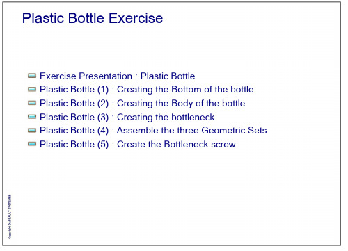
Plastic Bottle ExerciseExercise Presentation : Plastic BottlePlastic Bottle (1) : Creating the Bottom of the bottlePlastic Bottle (2) : Creating the Body of the bottlePlastic Bottle (3) : Creating the bottleneckPlastic Bottle (4) : Assemble the three Geometric Sets Plastic Bottle (5) : Create the Bottleneck screwExerciseExercise Presentation: Plastic Bottle3 HoursIn this exercise you will see how to create a plastic bottle u sing the Generative Shape Design workbenchf unctionalities :Creating wireframe elements (point, line, plane..)Creating surfaces (sweep,loft, extrude,revolve…)Manipulating surfaces (trim, symmetry, join…)Design Intent : Plastic BottleCreation of wireframe geometry : points, lines, planes, helix using the stacking commandscapabilities and working on supportCreation of surfaces using Sweep, Loft, Extrude and Revolve Operations on surfaces using Fillets, Trim, Join and healing Analysing the surfaces using the connect checker.Design Process : the Plastic Bottle1Create theBottom of thebottle4Assemble the threeGeometrical Set Create theBottleneck3Create thebody of thebottle 25Create thebottleneck screw on the assembledpartPlastic BottleStep 1: Creating the bottom of the bottle.30 minComplete the existing wireframe geometry.Create the bottom’s bottle surfacesPart used: start_bottle.CATPartIntersect.1Intersect.4(2)Sketch.2(3)1- Insert a new Geometrical Set , rename it as Bottle_Bottom.2- Create an Intersection point between the Intersect.1 axis and the green profile Sketch.2.3- Working on the ZX plane support, draw a circle by Center and point (creating the center point on the fly) with the following characteristics :•Center point on the pink axis and 5 mm below the Intersection point just created (Intersect.4) •Intersect.4 as point and –90 and 90 degrees as Start and End angle.(6) (4)(7)(9)4- Create a point on plane (-15mm ; -20mm) with the Intersect.4 as reference.5- Create a Symmetry of this point using the pink axis (Intersect.1) as reference.6- Using these two points, create two bi-tangent lines with the previous circle.7- Trim the two created lines with the circle.8- Exit the Work on support mode.9- Create two symmetric planes with an angle of 36 degrees with the YZ reference plane.Do It Yourself (3/4)(11)(10)(12)10- Create an Explicit sweep using the Trim.2 as profile and the green Sketch.2 as Guide curve.11- Create a 180 degrees revolved surface using the Sketch.1 as profile and the Intersect.1 as axis.12- Trim the two created surfaces.Do It Yourself (4/4)(13)(14)(16)(15)13- Create a Variable edge fillet as shown.14- Split the created EdgeFillet.1 with the two 36 degrees planes created before. 15- Create 4 Rotate surfaces (72 degrees) to complete the bottom.16- Join the created surfaces and rename the Join as Bottle_Bottom.Plastic BottleStep 2: Creating the body of the bottle.20 minComplete the existing wireframe geometry.Create the body’s bottle surfaces.Part used: bottle_step2begin.CATPartCircle.1Parallel.3(2)Sketch.4Parallel.1 Parallel.2Sketch.4 Plane.2Circle.1(4) (5)(3)1- Insert a new Geometrical Set, rename it as Bottle_Body.2- Create two parallel curves of the Sketch.4 on the ZX plane at a distance of 3mm in both directions. 3- Create a parallel curve of the Circle.1 on the Plane.2 at a distance of 1.6mm inward.4- Create 2 Combined curves between the Circle.1 and the two curves Parallel.1 and Parallel.25- Create a Combined curve between the Sketch.4 and the Parallel.3(7)(6)6- Create an Implicit Circular Swept surface with three guides using the three created combinedcurves as guide curves.7- Create 3 instances of this Sweep using a Translate along the Z axis and the Repeat object after OK option. For the distance between the instances, create the formula :‘Starting_crv\Plane.2\Plane offset.1\Offset’ /58- Join the created surfaces with the original sweep.Sketch.3(11)(9)(10)(12)9- Create a Revolved surface using the Sketch.3 as profile and the the Intersect.1 as Revolution axis.10- Trim the created revolved surface with the previous Join.11- Create a 2 mm edge fillet on the edges resulting of the previous Trim.12- Rename the created fillet as Bottle_Body.Plastic BottleStep 3: Creating the bottleneck.60 minComplete the existing wireframe geometry.Create the bottleneck surfaces.Do It Yourself (1/8)Part used: bottle_step3begin.CATPartIntersect.3Point.3Plane.2Intersect.2(1)(2)(3)1- Insert a new Geometrical Set, rename it as Bottleneck.2- Create a Point between the Intersect.2 and Intersect.3 points with a ratio of 0.6 3- Create a plane parallel to the Plane.2 through the created Point.34- Draw the following Sketch on the ZX plane.Plane.3(5)Intersect.35- Create two extrema ( Minimum and Maximum) on the sketch in the Z direction.(7)(6) (8)6- Create a Revolved surface using the Sketch.3 as profile and the Intersect.1 as Revolution axis.7- Create a Boundary curve with the lower edge of the revolution surface.8- Create a point on the boundary using a 0.125 ratio of curve length, and using the Point “Extremum.2”as reference point.(10)(9)9- Create a 12 mm Extruded surface with the Circle.1 in the Z axis direction upward.10- Create a Boundary curve with the upper edge of the extruded surface.11- Create a 35 mm radius circle on the Plane.5 with the Point.3 as center.(11)(12)(13)12- Create two projected points of Extremum.2 on the Circle.3 and on the Boundary.213- Create a Multisection Surface between the three sections : Boundary.1 ; Circle.3 ; Boundary.2 Use the boundaries surfaces as tangents and the Extremum.2 and its projections as closing points(14)(15)14- Create a Line on the Loft. Starting from the extremum.2 with an angle of 45 deg with the upperboundary and with a length of 500 mm.15- Create a second line on the Loft, starting of the Point.4 with all the same characteristics than the previous line.(14)(16)(15)14- Create a new boundary curve on the revolution surface relimited by the two previous lines.15- Create a second boundary on the Extruded surface relimited by the two previous lines. 16- Hide the Loft and create a Fill surface with four previous curves.Do It Yourself (8/8)(18)(17)17- Create 7 rotated instances of the fill surface around the intersect.1 axis (45 deg rotation).18- Join all these rotated surfaces with the fill surface, and with the extruded and the revolved surfaces. 19- Rename the join as Body_style.Plastic BottleStep 4: Assemble the three Geometric Sets.20 minComplete the existing wireframe geometry.Assemble the previous bodies with trim operations and fillets.Do It Yourself (1/5)Part used: Bottle_Step4Begin.CATPart(1)(2)1- Insert a new Geometric Set, rename itBottle_Assembled.2- Create a 2mm upward offset plane from the Plane.1.3- Create a 2mm downward offset plane from thePlane.2.(3)(4)(6)(5)4- Create an Intersection between the Plane.7 and the Bottle_Body.5- Create an Intersection between the Plane.6 and the Bottle_Body.6- Create an Intersection element between the Plane.1 and the Bottle_Bottom.(7) (8)7- Create an Implicit linear swept surface with two guide curves : Intersect.6 and Intersect.7 8- Create an Implicit linear swept surface with two guide curves : Intersect.5 and Circle.1(9)(11) (10)(12)9- Trim the upper swept surface with the Bottle_Body. 10- Trim the previous Trim with the Body_Style surface. 11- Trim the lower swept surface with the Bottle_Bottom. 12- Trim the two last trims.Do It Yourself (5/5)(13)(14) 13- Create a 6mm EdgeFillet on the two sharp edges.14- Rename the fillet as Bottle_Assembled.Plastic BottleStep 5: Creating the bottleneck screw.20 minComplete the existing wireframe geometry.Create the screw surfaces.Part used: Bottle_Step5Begin.CATPart1- Insert a new Geometrical Set, rename it as Bottleneck_Screw.2- Create on the fly a point and a plane with the characteristics shown below.(2)(3)(4)3- Create a Helix starting from the last created Point.5 with Intersect.1 as axis and with the followingparameters : Pitch = 3 mm / Height = 7mm / Orientation = Counterclockwise4- Create a line normal to the helix on the last Plane.8 starting at 1.6mm from the Point.5 with a Length of 20mm(5)(6) 5- Create a point on the helix at a distance of 0.8mm from the starting Point.56- Create a Connect Curve to link the Helix with the Line.5Do It Yourself (4/4)(7)(8)7- Create an Implicit circular profile swept surface. Choose Center and radius as subtype, Connect.1 as Center curve and a radius of 0.8mm.8- Trim the created sweep with the assembled bottle.。
- 1、下载文档前请自行甄别文档内容的完整性,平台不提供额外的编辑、内容补充、找答案等附加服务。
- 2、"仅部分预览"的文档,不可在线预览部分如存在完整性等问题,可反馈申请退款(可完整预览的文档不适用该条件!)。
- 3、如文档侵犯您的权益,请联系客服反馈,我们会尽快为您处理(人工客服工作时间:9:00-18:30)。
(4)
(5)
(3)
1- Insert a new Geometrical Set, rename it as Bottle_Body. 2- Create two parallel curves of the Sketch.4 on the ZX plane at a distance of 3mm in both directions.
Copyright DASSAULT SYSTEMES
Plastic Bottle
Step 3: Creating the bottleneck.
60 min
Complete the existing wireframe geometry. Create the bottleneck surfaces.
Copyright DASSAULT SYSTEMES
Do It Yourself (2/3)
(7)
(6)
6- Create an Implicit Circular Swept surface with three guides using the three created combined curves as guide curves.
30 min
Complete the existing wireframe geometry. Create the bottom’s bottle surfaces
Copyright DASSAULT SYSTEMES
Do It Yourself (1/4)
Intersect.1
Intersect.4
Creating wireframe elements (point, line, plane..) Creating surfaces (sweep,loft, extrude,revolve…) Manipulating surfaces (trim, symmetry, join…)
Copyright DASSAULT SYSTEMES
Copyright DASSAULT SYSTEMES
Do It Yourself (1/8)
Part used: bottle_step3begin.CATPart
Intersect.3
Point.3 Plane.2 Intersect.2
(1)
(2)
(3)
1- Insert a new Geometrical Set, rename it as Bottleneck. 2- Create a Point between the Intersect.2 and Intersect.3 points with a ratio of 0.6 3- Create a plane parallel to the Plane.2 through the created Point.3
Part used: start_bottle.CATPart
Sketch.2
(2)
(3)
Copyright DASSAULT SYSTEMES
1- Insert a new Geometrical Set , rename it as Bottle_Bottom.
2- Create an Intersection point between the Intersect.1 axis and the green profile Sketch.2.
Copyright DASSAULT SYSTEMES
Do It Yourself (4/4)
(13)
(14)
(16) (15)
13- Create a Variable edge fillet as shown. 14- Split the created EdgeFillet.1 with the two 36 degrees planes created before. 15- Create 4 Rotate surfaces (72 degrees) to complete the bottom. 16- Join the created surfaces and rename the Join as Bottle_Bottom.
Copyright DASSAULT SYSTEMES
Do It Yourself (1/3)
Part used: bottle_step2begin.CATPart
(2)
Sketch.4
Plane.2
Circle.1
Parallel.1
Parallel.2
Parallel.3 Sketch.4
Circle.1
3- Create a parallel curve of the Circle.1 on the Plane.2 at a distance of 1.6mm inward. 4- Create 2 Combined curves between the Circle.1 and the two curves Parallel.1 and Parallel.2 5- Create a Combined curve between the Sketch.4 and the Parallel.3
8- Join the created surfaces with the original sweep.
Copyright DASSAULT SYSTEMES
Do It Yourself (3/3)
Sketch.3
(11) (9)
(10)
(12)
9 - Create a Revolved surface using the Sketch.3 as profile and the the Intersect.1 as Revolution axis. 10- Trim the created revolved surface with the previous Join. 11- Create a 2 mm edge fillet on the edges resulting of the previous Trim. 12- Rename the created fillet as Bottle_Body.
Create the body of the
bottle 2
Copyright DASSAULT SYSTEMES
5
Create the bottleneck screw on the assembled
part
Plastic Bottle
Step 1: Creating the bottom of the bottle.
Design Intent : Plastic Bottle
Creation of wireframe geometry : points, lines, planes, helix using the stacking commands capabilities and working on support Creation of surfaces using Sweep, Loft, Extrude and Revolve Operations on surfaces using Fillets, Trim, Join and healing Analysing the surfaces using the connect checker.
Copyright DASSAULT SYSTEMES
Exercise
Exercise Presentation: Plastic Bottle
3 Hours
In this exercise you will see how to create a plastic bottle using the Generative Shape Design workbench functionalities :
Copyright DASSAULT SYSTEMES
Plastic Bottle
Step 2: Creating the body of the
20 min
Complete the existing wireframe geometry. Create the body’s bottle surfaces.
7- Create 3 instances of this Sweep using a Translate along the Z axis and the Repeat object after OK option. For the distance between the instances, create the formula : ‘Starting_crv\Plane.2\Plane offset.1\Offset’ /5
Copyright DASSAULT SYSTEMES
Design Process : the Plastic Bottle
1
Create the Bottom of the
bottle
4
Assemble the three Geometrical Set
3
Create the Bottleneck
Copyright DASSAULT SYSTEMES
Do It Yourself (3/4)
(11) (10)
(12)
10- Create an Explicit sweep using the Trim.2 as profile and the green Sketch.2 as Guide curve. 11- Create a 180 degrees revolved surface using the Sketch.1 as profile and the Intersect.1 as axis. 12- Trim the two created surfaces.