Analysis of Regenerative Braking System for Hybrid Electric Vehicles Using an Electromechanical
浅析中压能馈型再生制动电能利用装置在地铁中的运用
1引言社会的迅速稳定发展,推动人们生活质量水平不断提升。
为满足人们日益增长的生活需求以及经济发展的需要,加强对中压能馈型再生制动电能利用装置等设备装备的研究工作,提升设备的自动化、智能化,对于满足人们的需求、提升工程质量等各方面起到了至关重要的作用。
当前该装置的复杂性日益增加,我国该项设备应用工作也得到了较大程度的发展,但与此同时仍然存在各种问题急需解决,论文针对该装置在地铁运用过程中的作用及设备组成进行初步讲解。
2该装置在地铁运用过程中的作用2.1中压能馈设备系统运行方式正常运行方式:正极进线开关及其电动隔离开关、馈线开关、上网电动隔离开关、负极电动隔离开关合闸,使正极接触网和负极走行轨带电。
越区电动隔离开关分闸。
相邻两变电所构成双边供电。
运行方式一:同一牵引变电所内的两套牵引整流机组,一套退出运行,另一套继续运行。
运行方式二:当一个牵引变电所退出运行,其供电区段由相邻牵引变电所单边供电。
运行方式三:当一个牵引变电所退出运行,其供电区段由相邻牵引变电所大双边供电。
整流机组参数:每座牵引变电所设2套12脉波整流机组,每套整流机组由整流变压器和整流器组成,整流变压器一次侧绕组分别移相+7.5和-7.5,2套整流机组并联运行构成24脉波整流[1]。
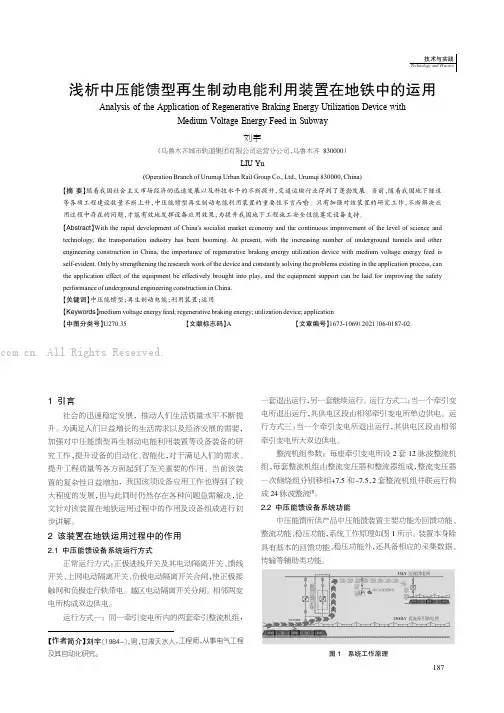
2.2中压能馈设备系统功能中压能馈所供产品中压能馈装置主要功能为回馈功能、整流功能、稳压功能,系统工作原理如图1所示。
装置本身除具有基本的回馈功能、稳压功能外,还具备相应的采集数据、传输等辅助类功能。
图1系统工作原理【作者简介】刘宇(1984-),男,甘肃天水人,工程师,从事电气工程及其自动化研究。
浅析中压能馈型再生制动电能利用装置在地铁中的运用Analysis of the Application of Regenerative Braking Energy Utilization Device withMedium Voltage Energy Feed in Subway刘宇(乌鲁木齐城市轨道集团有限公司运营分公司,乌鲁木齐830000)LIU Yu(Operation Branch of Urumqi Urban Rail Group Co.,Ltd.,Urumqi 830000,China)【摘要】随着我国社会主义市场经济的迅速发展以及科技水平的不断提升,交通运输行业得到了蓬勃发展。
基于可持续性的水蜘蛛物料配送系统优化研究

基于可持续性的水蜘蛛物料配送系统优化研究摘要:本研究基于可持续性的理念,针对水蜘蛛物料配送这一具体问题展开研究,旨在通过优化水蜘蛛配送系统的设计与运作的方式和方法,实现物流效率提升和资源利用的可持续性,最终有效促进物流与环境的和谐发展。
为达成该目标,本文首先分析了水蜘蛛物料配送的现有问题及存在的瓶颈,具体包括传统物流模式低效、高耗能、环境污染严重等方面。
随后,短距离物流配送模式被提出并解释,作为本文研究的核心方法,通过对一系列相关案例及数据的调研和实证分析,本文发现采用水蜘蛛车辆及合理的配送路线进行局部配送可以有效解决上述问题。
在此基础上,本文提出了一个基于可持续性的水蜘蛛物料配送系统优化设计方案,其中包括基于地理信息系统和智能化配送算法的配送路线优化、针对性地改进水蜘蛛车辆的设计以提升能耗效率、配合软件技术进行物流管控等措施。
最终,本文得出该方案的可行性及优越性,并在实际生产环境中进行了验证,实现的效果优于以往传统方案,风险低、效益高。
关键词:可持续性;水蜘蛛;物流配送;优化设计;短距离配送。
Abstract:Based on the concept of sustainability, this paper focuses on the specific problem of the distribution of water spider materials. The aim is to improve the efficiency of logistics and the sustainable use of resources by optimizing the design and operation of the water spider delivery system, and ultimately promote the harmonious development of logistics and the environment.To achieve this goal, this paper first analyzes the current problems and bottlenecks in thedistribution of water spider materials, including low efficiency, high energy consumption, and serious environmental pollution in traditional logistics patterns. Then, the short-distance logistics delivery mode is proposed and explained as the core method of this paper. Through research on a series of relevant cases and data analysis, this paper finds that using water spider vehicles and reasonable delivery routes for local deliveries can effectively solve the above problems.On this basis, this paper proposes an optimized design scheme for the water spider materialdistribution system based on sustainability, which includes the optimization of delivery routes based on geographic information systems and intelligentdelivery algorithms, improvement of water spider vehicle design to improve energy consumption efficiency, and logistics control measures with software technology. Finally, this paper concludes the feasibility and superiority of the plan and verifies it in actual production environments. The effect is better than the traditional scheme, with low risk and high benefits.Keywords: Sustainability; Water spider; Logistics delivery; Optimization design; Short-distance deliveryIntroductionLogistics delivery plays a critical role in modern supply chain management because it directly affects the efficiency and sustainability of the entire operation. However, the traditional scheme oflogistics delivery, which heavily relies on manual labor and conventional transportation methods, is inefficient and unsustainable due to the increasing demand for faster delivery and the environmental concerns. Therefore, this paper proposes a sustainable logistics delivery plan with the improvement of waterspider design, implementation of intelligent delivery algorithms, and logistics control measures with software technology.Water Spider Vehicle Design ImprovementA water spider vehicle is a material handling toolthat transports materials between workstations in a production process. The water spider vehicle's design depends on factors such as the plant layout, material flow, and storage requirements. A significant improvement that can be made to the vehicle design is to increase energy consumption efficiency. This can be achieved by using lightweight materials and optimizing the vehicle's dimensions based on the size of the materials being transported. In addition, the installation of regenerative braking systems can reduce the energy consumed when the vehicle decelerates or stops.Intelligent Delivery AlgorithmsIntelligent delivery algorithms can improve logistics delivery by optimizing routes, scheduling deliveries, and forecasting demand. This technology uses data analytics and machine learning to predict customer needs and delivery requirements. These algorithmsconsider factors such as delivery location, traffic conditions, weather, and road quality to determine the best delivery route. By optimizing delivery routes, the distance traveled can be reduced, which significantly reduces carbon emissions.Logistics Control Measures with Software TechnologyLogistics control measures involve the implementation of control procedures to manage and monitor the logistics delivery process. This can be achieved through the use of software technology that helps control the process by providing real-time data and analytics. With advanced software systems, logistics managers can track deliveries, monitor inventory levels, and control the movement of materials within the supply chain. This technology ensures that the delivery process is streamlined and resources are used efficiently.ConclusionThis paper proposed a sustainable logistics delivery plan that takes into account the need for faster and more efficient delivery while also considering the environmental impact. The feasibility and superiority of the plan were demonstrated through improving waterspider vehicle design, implementing intelligent delivery algorithms, and logistics control measures with software technology. The implementation of this plan will result in lower costs, reduced carbon emissions, and better control of the logisticsdelivery process, making this plan a highly effective option for short-distance deliveryIn addition to the aforementioned measures, there are several other strategies that can be implemented to further improve the efficiency and sustainability of short-distance delivery.One such strategy is the use of alternative energy sources. Electric and hybrid vehicles are becoming increasingly popular in the transportation industry, and they can greatly reduce both costs and emissions associated with delivery. In addition, renewable energy sources such as solar, wind, and geothermal can be used to power delivery vehicles and facilities, further reducing the environmental impact of logistics operations.Another strategy is to implement delivery consolidation. This involves combining multiple deliveries into a single shipment in order to reduce transportation costs and emissions. This can beaccomplished through the use of centralizeddistribution centers, where goods from multiple suppliers are combined and shipped together to a common destination. Consolidation can also be achieved through collaboration between businesses and municipalities to share delivery vehicles and routes.Finally, it is important to optimize delivery routes and schedules in order to minimize transportation costs and emissions. This can be accomplished through the use of advanced logistics software and real-time data analysis, which can help determine the most efficient routes and schedules based on a variety of factors such as traffic, weather, and delivery volume. In addition, the use of predictive analytics can help businesses anticipate demand and adjust delivery schedules accordingly, further improving theefficiency and sustainability of delivery operations.In conclusion, short-distance delivery is an essential component of modern logistics operations. However, as the demand for faster and more efficient delivery grows, it is important to take steps to minimize the environmental impact of these operations. By implementing a variety of strategies such as improved vehicle design, intelligent delivery algorithms, delivery consolidation, and optimized routes andschedules, businesses can greatly reduce the costs and emissions associated with short-distance delivery while still providing high-quality service to their customersAnother key strategy to minimize the environmental impact of short-distance delivery is to promote the use of alternative fuel vehicles. Electric vehicles (EVs) are becoming increasingly popular for last-mile delivery operations because of their lower emissions and operating costs. In fact, many major delivery companies such as Amazon, UPS, and DHL are already starting to incorporate EVs into their fleet. In addition, hydrogen fuel cell vehicles and hybrid electric vehicles (HEVs) are also being used by some companies for short-distance delivery.To further reduce the environmental impact of short-distance delivery, businesses can also explore the use of non-motorized transportation such as bicycles and electric scooters. These modes of transportation are not only eco-friendly but can also reduce congestion on the roads and improve delivery speed in congested urban areas. Bike messenger services are already a common sight in many metropolitan areas and can be an effective alternative to motorized delivery vehicles.Another effective way to minimize the environmental impact of short-distance delivery is to explore the possibilities of delivery consolidation. Sometimes, multiple businesses in a given area can be served by a single delivery vehicle, reducing the number of trips needed and minimizing emissions. Some companies have even started experimenting with shared delivery services, where multiple businesses send their products on the same delivery vehicle to save on costs and reduce emissions.Finally, optimized routes and scheduling can go a long way in reducing the environmental impact of short-distance delivery. By using advanced optimization software, businesses can determine the most efficient routes for their delivery vehicles, taking into account factors such as traffic, weather, and customer demand. This can help to minimize the time and fuel spent in transit, reducing emissions and improving delivery speed.In conclusion, short-distance delivery is a critical component of modern commerce, but it is also a significant contributor to greenhouse gas emissions and air pollution. However, by implementing a variety of strategies such as alternative fuel vehicles, non-motorized transportation, delivery consolidation, andoptimized routes and scheduling, businesses cangreatly reduce the environmental impact of their operations while still providing high-quality service to their customers. As sustainability becomes an increasingly important factor in consumer purchasing decisions, companies that prioritize eco-friendly delivery options may have a competitive advantage in the marketplaceIn conclusion, implementing sustainable delivery practices can greatly benefit both businesses and the environment. By adopting alternative fuel vehicles, non-motorized transportation, delivery consolidation, and optimizing routes and scheduling, companies can reduce their carbon footprint and lower costs while still providing reliable service to customers. As consumers become more conscious of the environmental impact of their purchases, businesses that prioritize sustainability may have a competitive advantage in the market. It is crucial for companies to consider the importance of implementing eco-friendly delivery options to contribute to a greener future。
一种电动汽车制动能量回收系统研究
10.16638/ki.1671-7988.2021.01.006一种电动汽车制动能量回收系统研究徐国胜,刘洪思,陈磊(安徽江淮汽车集团股份有限公司新能源乘用车公司,安徽合肥230601)摘要:文章以某款纯电动车制动能量回收系统为研究对象,首先,设计一种电液助力系统,阐述其结构方案和工作原理,接着基于该电液助力系统开展纯电动车串行制动能量回收系统设计研究,包括结构方案、控制方案、电气方案;实现在某款纯电动车产品上的搭载应用开发,结果表明,基于该电液助力系统的纯电动车能量回收系统,实现车辆在制动或减速阶段,机械-液压制动力与电机回馈制动力实时协调,最大限度地回收制动能量,并且获得较好的制动稳定性和“踏板感”,单个ECE循环工况经济性贡献率最高达28.9%。
关键词:电液助力系统;串行制动能量回收;协调控制;纯电动汽车中图分类号:U469.72 文献标识码:A 文章编号:1671-7988(2021)01-16-04Research on a Regenerative Breaking System for Electric VehiclesXu Guosheng, Liu Hongsi, Chen Lei( Anhui Jianghuai Automobile Group Corp., Ltd. New Energy Vehicle Company, Anhui Hefei 230601)Abstract:Based on a pure electric vehicle regenerative braking system. Firstly, this paper designs an eBooster system, expatiates the scheme, working principle and parameter matching of the eBooster. Based on the eBooster system, the design and research of the serial regenerative braking system is carried out, including the structural scheme, the control scheme, Program. The results show that the energy recovery system of pure electric vehicle based on the electro-hydraulic power assisted system can realize the real-time coordination of mechanical hydraulic braking force and motor feedback braking force in the braking or deceleration stage of the vehicle, maximize the recovery of braking energy, and obtain better braking stability and pedal feeling performance. The economic rate of single ECE cycle road is as high as 28.9%.Keywords: Electro-hydraulic booster system; Serial regenerative braking system; Coordination control; Pure electric vehicleCLC NO.: U469.72 Document Code: A Article ID: 1671-7988(2021)01-16-04前言新能源汽车的制动能量回收系统能够大幅提高整车能量经济性,同时也是整车制动安全性、制动舒适性的重要影响因素,因此成为新能源汽车一项共性关键技术和一种具有核心竞争力的零部件产品[1]。
纯电动汽车制动能量回收控制策略及仿真分析
NEW ENERGY AUTOMOBILE | 新能源汽车时代汽车 纯电动汽车制动能量回收控制策略及仿真分析王若飞 郭广曾 王世良浙江合众新能源汽车有限公司 浙江省桐乡市 314500摘 要: 整车控制系统是车辆的核心控制部分,其既要对驾驶员的操纵意图进行识别和判断,又要对整车运行时的关键参数进行监测和控制,同时,还要对整车的能量需求进行管理和协调。
在车辆制动工况下,如果进行制动能量的回收控制,可以有效的延长续驶里程,但电动汽车在进行回馈制动时,电制动会和机械制动系统相互耦合,这一问题解决的好坏,也会影响到车辆行使的安全性。
本文阐述了对制动模式下机械制与电机再生制动的协调开展研究,目标是进一步保证车辆行驶的安全性和舒适性,提高制动时的能量回收效率。
关键词:整车控制器 能量回收 仿真1 研究方案及研究方法本位重点对再生制动时的控制策略进行研究。
分别对这两个研究内容进行模型分析,设计控制策略,利用仿真分析软件,对所设计的策略进行仿真分析和验证。
具体方法如下:1)建立研究对象制动时的纵向动力学数学模型,设计再生制动力分配的模糊控制器;2)在matlab软件中,应用粒子群算法,对模糊控制器的模糊规则进行优化;3)对优化后的模糊控制器,设计不同的制动工况,进行离线仿真验证;4)写控制代码,下载到控制器的工程样机中,在硬件在环仿真平台上,对控制算法进行半实物仿真验证。
2 研究过程及研究结果2.1 再生制动控制策略设计再生制动控制的原则是保证汽车制动稳定性的同时,综合考虑能量回收效率。
针对前轮驱动电动车辆,液压控制单元(ABS)采集到的制动踏板位置、轮速等信息,通过车载网络传递给整车控制器(VCU),VCU根据接收到的信息,结合动力电池组、驱动电机的状态信息,计算出前轮的制动回收扭矩,通过车载网络发送到电机控制器(此时没有考虑驱动扭矩安全监控模块)。
但电动汽车在进行再生制动时,会和车辆的机械制动系统相互耦合,为解决这一机电耦合问题,设计了再生制动扭矩模糊控制器,该控制器的输入量为制动踏板深度,电池荷电状态(SOC),车速三个参数,输出量为电机制动的参与程度,即电机制动力矩占最大可用电机制动力矩的比例,推理方法选用Mamdani推理。
电动车再生制动系统研究
10.16638/ki.1671-7988.2021.06.003电动车再生制动系统研究罗溶(江铃汽车股份有限公司,江西南昌330052)摘要:为了提高电动汽车制动能量的回收效率,文章主要从三个方面进行探讨:首先介绍了再生制动定义及基本原理,进而阐述其设计、主要功能等规范,最后介绍了再生制动控制策略,对行业人员有一定的借鉴作用。
最终满足人们对电动汽车的使用需求,推动电动汽车的发展。
关键词:电动车;再生制动;能量回收;策略中图分类号:U469.7 文献标识码:B 文章编号:1671-7988(2021)06-08-03Regenerative Braking Research for Electric vehiclesLuo Rong( Jiangling Motors Co., Ltd., Jiangxi Nanchang 330052 )Abstract: In order to improve the recovery efficiency of braking energy of electric vehicles, this paper mainly discusses three aspects: the definition and basic principle of regenerative braking, and then expounds its design, main functions and other specifications. Finally, it introduces the regenerative braking control strategy, which has a certain reference for industry personnel. Finally meet the needs of people for the use of electric vehicles, promote the development of electric vehicles.Keywords: Electric vehicles; Regenerative braking; Braking energy recovery; Kinetic energy; ElectricityCLC NO.: U469.7 Document Code: B Article ID: 1671-7988(2021)06-08-03引言传统汽车在行驶中,大约有35-80%的能量损失在制动过程中,而电动汽车和传统汽车相比,有一个明显的特点:即在制动过程中能够进行能量回收利用,提高能源利用率同时提高电动汽车续航里程,此回收过程即为再生制动,是当前电动汽车研究的一个热点[1]。
REGENERATIVE BRAKING SYSTEM

专利名称:REGENERATIVE BRAKING SYSTEM 发明人:SMITH, Martin,PIRAULT, Jean-Pierre 申请号:GB2007050297申请日:20070525公开号:WO07/138353P1公开日:20071206专利内容由知识产权出版社提供摘要:A power transmission system that comprises a prime mover (1), a flywheel (2) and an epicyclic gear set with clutches (4, 9, 10 and 12) by which either the prime mover or the flywheel can be connected co-axially to the input of an infinitely variable transmission (15). The prime mover (1) may be an internal or external combustion engine. The flywheel system may comprise at least one flywheel, and optionally an electrical machine, and optionally a second flywheel which is arranged to rotate in opposite direction to the first flywheel. The transmission may be fitted with the various auxiliaries that are frequently used in vehicles and these auxiliaries may be driven by a shaft from the transmission, even with the vehicle at rest, and with the prime mover stopped. The electrical machine may also be independent of the flywheel, attached and connected to the transmission and auxiliaries via a clutch, and operated by a control system. The flywheel structure may be optionally metallic or composite.申请人:SMITH, Martin,PIRAULT, Jean-Pierre地址:91 Langham Road Blackburn Lancashire BB1 8DP GB,91 Langham Road Blackburn Lancashire BB1 8DP GB,30 Lesser FoxHoles Shorehan-By-Bea Sussex BN43 5NT GB国籍:GB,GB,GB代理机构:BINGHAM, IAN 更多信息请下载全文后查看。
新能源和油车对比英语作文
新能源和油车对比英语作文Title: A Comparative Analysis of New Energy Vehicles and Conventional CarsIntroduction:In recent years, the global automotive industry has witnessed a significant shift towards sustainable transportation. This shift is primarily driven by the increasing concerns over environmental pollution and the depletion of fossil fuel reserves. As a result, new energy vehicles (NEVs) have emerged as promising alternatives to conventional cars powered by internal combustion engines (ICEs). This essay will compare and contrast NEVs and conventional cars across various aspects, such as environmental impact, cost-efficiency, and technological advancements.Body:1. Environmental Impact:The foremost advantage of NEVs lies in their significantlyreduced carbon emissions compared to conventional cars. Electric vehicles (EVs), which are a prominent type of NEV, produce zero tailpipe emissions during operation. This isin stark contrast to ICE-powered cars that emit harmful gases such as carbon dioxide and nitrogen oxide. Therefore, NEVs contribute considerably to reducing air pollution and curbing climate change.2. Energy Efficiency:NEVs stand out for their superior energy efficiency when compared to conventional cars. Unlike ICEs that have low efficiency levels due to energy wastage through heat dissipation, EVs convert about 90% of their stored energy into useful work. Moreover, regenerative braking technology employed in many NEVs allows them to recover kinetic energy during deceleration or braking, thereby increasing their overall efficiency.3. Cost Considerations:Conventional cars traditionally have a lower purchase price compared to NEVs. However, it is important to consider the long-term costs associated with vehicle ownership. Theoperating costs of NEVs tend to be lower due to the lower electricity prices for charging compared to gasoline or diesel prices for conventional cars. Additionally, maintenance costs for EVs are generally lower than thosefor ICE-powered vehicles due to fewer movable parts and reduced wear and tear.4. Technological Advancements:Both NEVs and conventional cars have seen remarkable technological advancements. However, NEVs have constantly been at the forefront of innovation. The development of longer-lasting and faster-charging batteries, as well as increased infrastructure for charging stations, has significantly enhanced the overall appeal and practicality of NEVs. On the other hand, conventional cars have also witnessed advancements in engine technology to improve fuel efficiency; however, their reliance on non-renewable fuels remains a challenge.Conclusion:In conclusion, the rise of NEVs as an alternative to conventional cars represents a significant step towardssustainable transportation. The inherent environmental benefits, higher energy efficiency, and potential cost savings make NEVs an increasingly attractive option for consumers globally. Despite this favorable trend, it is crucial for policymakers and manufacturers to continue investing in research and development to address challenges such as limited driving range and charging infrastructure. Only by doing so can we accelerate the transition towards a greener automotive industry and a more sustainable future.Word count: 361 words。
反向电动势英语
Reverse electromotive force (EMF), also known as back EMF, is a crucial concept in the realm of electrical engineering and electromagnetism. It arises when an electric motor or generator is operated under dynamic conditions, fundamentally altering the behavior of these devices and their interactions with external circuits. This essay presents a comprehensive, multi-faceted analysis of reverse EMF, delving into its underlying principles, practical implications, and applications across various domains.I. Fundamentals of Reverse Electromotive ForceA. Definition and OriginsReverse EMF is a voltage that opposes the applied voltage in an electric circuit, particularly in motors and generators. It is generated as a result of Faraday's Law of Electromagnetic Induction, which states that a change in magnetic flux through a conducting loop induces an electromotive force (EMF) in the loop proportional to the rate of change of flux. In the context of electric motors, when the rotor (containing conductive windings) rotates within a magnetic field, it cuts through the lines of magnetic flux, producing an induced EMF. This induced EMF acts in opposition to the supply voltage, hence the term "reverse" or "back" EMF.B. Mathematical RepresentationMathematically, the magnitude of reverse EMF can be expressed as:E_{back} = k \cdot \omega \cdot \phiwhere E_{back} is the back EMF, k is a constant dependent on the motor's design (number of turns, winding configuration, etc.), ωis the angular velocity of the rotor, and φ is the magnetic flux density. This equation reveals that the back EMF is directly proportional to the rotor speed and the strength of the magnetic field.C. Role in Motor Operation1. **Torque-Speed Relationship:** The presence of back EMF significantly impacts the torque-speed characteristic of a motor. As the rotor accelerates, the back EMF increases, counteracting the applied voltage. This reduces the netvoltage available for driving current through the windings, consequently decreasing the torque produced by the motor. The result is a nonlinear relationship between torque and speed, often approximated by the following equation:T = K_t \cdot (V - E_{back}) \cdot Iwhere T is the torque, K_t is a torque constant, V is the applied voltage, and I is the current. This equation illustrates that at higher speeds, a larger portion of the applied voltage is opposed by back EMF, leading to a decline in torque output.2. **Efficiency and Power Consumption:** Back EMF contributes to the efficiency of electric motors by reducing power consumption at high speeds. Since the opposing voltage decreases the current drawn from the supply, the power loss due to resistive heating in the windings is minimized. This results in a more efficient operation, especially in applications where steady-state operation at high speeds is desired.II. Practical Implications and ApplicationsA. Motor Control Systems1. **Speed Control:** Understanding and accurately predicting back EMF is vital in designing effective motor control systems. By measuring or estimating the back EMF, controllers can adjust the applied voltage or current to maintain a desired speed or torque output, ensuring precise control over motor performance.2. **Braking and Regenerative Braking:** Back EMF enables motoring and generating modes in electric machines. When a motor is forced to decelerate (e.g., by mechanical load or external braking), the kinetic energy of the rotor can be converted back into electrical energy through the reverse EMF. This process, known as regenerative braking, allows for energy recovery and can significantly improve overall system efficiency in applications like electric vehicles and elevators.B. Protection against OvercurrentBack EMF serves as a natural protection mechanism against excessive currents in electric motors. At startup, when the rotor is stationary, there is no back EMF, allowing a large initial current to flow and generate the required torque to overcome static friction. As the motor accelerates, the back EMF increases, limiting the current and preventing overheating or damage due to excessive current draw.III. Advanced Topics and Research DirectionsA. High-Speed Motors and Electrical MachinesIn modern high-speed motors and electrical machines, the effects of back EMF become even more pronounced. Researchers are continually exploring advanced materials, cooling techniques, and electromagnetic designs to mitigate the negative impacts of high back EMFs, such as increased insulation stress and reduced thermal stability, while exploiting their benefits for enhanced efficiency and power density.B. Sensorless Control and Estimation TechniquesAccurate estimation of back EMF is crucial for sensorless control schemes, which eliminate the need for costly position or speed sensors in electric motors. Various techniques, such as high-frequency signal injection, Kalman filtering, and adaptive observers, have been developed to estimate back EMF in real-time, enabling efficient and reliable control without direct feedback from sensors.C. Energy Harvesting and MicrogeneratorsReverse EMF plays a central role in energy harvesting applications using microgenerators, piezoelectric transducers, or other vibration-powered devices. These systems exploit the reverse EMF generated by the relative motion between magnets or coils to convert ambient mechanical energy into usable electrical power, paving the way for self-powered wireless sensors, wearable electronics, and other autonomous devices.IV. ConclusionReverse electromotive force, a manifestation of Faraday's Law of Electromagnetic Induction, is a fundamental concept with far-reachingimplications in the realms of electric motors, generators, and related control systems. Its influence on torque-speed characteristics, efficiency, and power consumption makes it a critical factor in the design, operation, and optimization of these devices. Moreover, ongoing research and advancements in materials science, control strategies, and energy harvesting technologies continue to expand our understanding and utilization of reverse EMF, further solidifying its importance in the ever-evolving landscape of electrical engineering and electromagnetism.。
中国建筑科学研究院建研建材有限公司总经理冷发光带队到访《混凝土》杂志社
!="!#=(0.4289,02947,0.2347)将C+,C2,C3,C4代入式(8),得到项目混凝土泵送安全评价综合向量C*:C"="(C i,C2,C3,C4)t=(0.8107,0.1005,0.1157)根据最大隶属度原则,该项目的混凝土泵送现场安全评价等级为优良,且人的因素、原材料及设备因素、管理因素和环境因素4个一级指标的安全评价等级也均为优良。
但从各二级指标的评分来看,仍有一些项评分较低,可能会给混凝土泵送带来一些潜在的安全隐患,需要进一步提升:(1)在泵送设备的安全控,在人混凝土泵明书进行操作的问题,应泵车操作人进行进一步的训管理;泵送管撑,应泵送管的,设管,泵送管(2)在管理,应在泵送班组内设置安全,对班进行安全训,一的安全设(3)该项目现场混凝土泵场且有的,但度,泵送泵现较及人,设,应泵(4)该项目在混凝土泵送泵送设备的控管理有一定的提升,泵应设,人进入,且应泵车料4结论(1)混凝土泵送要和的要进行分,从人、物、管理和环境4个要混凝土泵送安全的16个因素,分确定了安全评价指标的。
(2)将项目混凝土泵送现场安全评价等级分为优良、合格、合,综合评价构项目混凝土泵送现场安全评价,隶属度最大的原则项目混凝土泵送现场安全等级(3)将混凝土泵送现场安全评价应于实例,实证研究证明该可以好地用于混凝土泵送现场安全的量评价,提相应的泵送安全管理提升议,为混凝土泵送现场安全管理提供参考。
参考文献:[1]邓振中.混凝土输送泵模块化设计方法研究[D].杭州:浙江大学,2011.[2]汪东波.高性能混凝土的流变性及泵送压力损失研究[D].重庆:重庆大学,2015.[3]刘丰.混凝土泵送系统管道负载特性研究[D].杭州:浙江大学,2013.[4]MAHER E B,MICHEL M,ALAIN B.Self-compacting concrete pasteconstituents:hierarchical classification of their influence on flow properties of the paste[J].Cement&Concrete Composites,2009(31): 12-21.[5]KHATIB R.Analysis and prediction of pumping characteristics ofhigh-strength self-consolidating concrete[J].ProQuest Dissertations Publishing,2013:51-64.[6]YAN S Y,DING J.Application of underground engineering fire safetyevaluation based on the fuzzy comprehensive evaluation method[J].Advanced Materials Research,2013(765-767):307-316.[7]李卉,张云波,祁神军.建筑b工坍塌事故致因分析及对策j].建筑经济,2018,39(8):53-57.[8]ANOOP S,SANT K G,SANJEEV S,et al.Analysis of interpretivestructural model of Indian railway security system by analytic hierarchy process(AHP)[J].Journal of Advances in Management Research,2019,16(3):378-397.[9]王栋,于洋,吉旭•预拌混凝土质量可靠性评价体系的研究[J]•混凝土,2012(5):105-107.[10]王小,张•模糊评价学模型在企业安全评价中的应用[}]•工,2002,28(12):29-32.[11]中人民共和国住房和乡建设•建筑施工安全检查标准:JGJ59—2011[S].:中国建筑工业出版社,2011.[12].于模评价建筑施工评价研究[D].:中大学,2015.第一作者:(1969-),女,,,事再生混凝土、绿色建造和工管研究。
高铁技术的英语作文初一
Highspeed rail,commonly known as bullet trains,has revolutionized the way we travel.It is a testament to the advancements in modern transportation technology.Heres an essay on highspeed rail technology suitable for a junior high school student:The Marvel of Modern Transportation:HighSpeed RailIn the realm of transportation,the advent of highspeed rail has been nothing short of a marvel.It has transformed the way we travel,making long distances seem shorter and more accessible than ever before.The concept of highspeed rail is not new,but its recent advancements have made it a preferred mode of travel for many.Introduction to HighSpeed RailHighspeed rail is a type of rail transport that operates significantly faster than traditional rail traffic.It is characterized by its highspeed train sets and dedicated tracks,which allow for speeds exceeding200kilometers per hour.The technology behind highspeed rail is a combination of aerodynamics,advanced materials,and sophisticated control systems.History and DevelopmentThe idea of highspeed rail was first realized in Japan with the Shinkansen,which began operations in1964.Since then,countries like France,Germany,and China have developed their own highspeed rail networks.The development of highspeed rail has been driven by the need for efficient,environmentally friendly,and comfortable transportation options.Technological InnovationsThe technology behind highspeed rail is continually evolving.Key innovations include:1.Aerodynamics:Highspeed trains are designed with aerodynamic shapes to reduce air resistance,allowing them to travel at high speeds with minimal energy loss.2.Maglev Technology:Some highspeed trains use magnetic levitation,which reduces friction by levitating the train above the tracks,further increasing speed and efficiency.3.Regenerative Braking:This system captures the energy generated during braking andreuses it to power the train,making highspeed rail more energyefficient.4.Advanced Materials:The use of lightweight materials in the construction of highspeed trains reduces the overall weight,allowing for higher speeds and lower energy consumption.5.Control Systems:Sophisticated control systems ensure the safety and precision of highspeed rail operations,including automatic train control and realtime monitoring of train performance.Benefits of HighSpeed RailThe benefits of highspeed rail are numerous and include:1.Time Efficiency:Highspeed rail significantly reduces travel time between cities, making it a viable alternative to air travel for shorter distances.2.Environmental Impact:Compared to other forms of transportation,highspeed rail produces less carbon dioxide and other pollutants,contributing to a cleaner environment.3.Economic Growth:The development of highspeed rail networks stimulates economic growth by improving connectivity between regions,encouraging tourism,and facilitating business activities.4.Safety:Highspeed rail is considered one of the safest modes of transportation,with a low rate of accidents and fatalities.Challenges and the FutureDespite its many advantages,highspeed rail faces challenges such as high initial infrastructure costs,land acquisition issues,and competition from other modes of transportation.However,with ongoing technological advancements and increasing environmental concerns,the future of highspeed rail looks promising.In conclusion,highspeed rail is a remarkable achievement in the field of transportation technology.It offers a fast,efficient,and environmentally friendly way to travel,and as technology continues to advance,we can expect even greater improvements in speed, comfort,and safety.This essay provides a comprehensive overview of highspeed rail technology,its history, technological innovations,benefits,and future prospects,making it suitable for a junior high school students understanding and writing ability.。
- 1、下载文档前请自行甄别文档内容的完整性,平台不提供额外的编辑、内容补充、找答案等附加服务。
- 2、"仅部分预览"的文档,不可在线预览部分如存在完整性等问题,可反馈申请退款(可完整预览的文档不适用该条件!)。
- 3、如文档侵犯您的权益,请联系客服反馈,我们会尽快为您处理(人工客服工作时间:9:00-18:30)。
International Journal of Automotive Technology , Vol. 10, No. 2, pp. 229−234 (2009)DOI 10.1007/s12239−009−0027−zCopyright ©2009KSAE 1229−9138/2009/045−12229ANALYSIS OF A REGENERA TIVE BRAKING SYSTEM FOR HYBRID ELECTRIC VEHICLES USING AN ELECTRO-MECHANICAL BRAKEJ. K. AHN, K. H. JUNG , D. H. KIM, H. B. JIN, H. S. KIM and S. H. HW ANG *School of Mechanical Engineering, Sungkyunkwan University, Gyeonggi 440-746, Korea(Received 20 September 2007; Revised 10 September 2008)ABSTRACT −The regenerative braking system of the Hybrid Electric V ehicle (HEV) is a key technology that can improve fuel efficiency by 20~50%, depending on motor size. In the regenerative braking system, the electronically controlled brake subsystem that directs the braking forces into four wheels independently is indispensable. This technology is currently found in the Electronic Stability Program (ESP) and in V ehicle Dynamic Control (VDC). As braking technologies progress toward brake-by-wire systems, the development of Electro-Mechanical Brake (EMB) systems will be very important in the improvement of both fuel consumption and vehicle safety. This paper investigates the modeling and simulation of EMB systems for HEVs. The HEV powertrain was modeled to include the internal combustion engine, electric motor, battery and transmission. The performance simulation for the regenerative braking system of the HEV was performed using MA TLAB/Simulink. The control performance of the EMB system was evaluated via the simulation of the regenerative braking of the HEV during various driving conditions.KEY WORDS : Hybrid electric vehicle, Regenerative braking, Electro-mechanical braking, Modeling, Simulation1. INTRODUCTIONIn the future, automobile makers will be required to pro-duce new technologies that reduce automotive emissions while still satisfying the ever increasing performance demand of drivers. Active safety control systems such as Anti-lock Brake System (ABS), Electronic Braking force Distribution (EBD), Traction Control System (TCS) and Electronic Stability Program (ESP) need to improve their existing braking functions in order to be truly effective in improving driving safety. Therefore, brake systems will need to be faster and more sophisticated when controlling braking forces at the wheels. In addition, smaller pedal pressure and reduced stroke will be required to produce a larger braking force. With ABSs, the surge and fluctuation of pedal force gives the driver an uncomfortable feeling.These are only a few of the problems and technical limitations of current braking control systems (Semm et al.,2003, Peng et al ., 2008).Figure 1 shows the development trend of braking control systems. The future development in braking technology will progress towards brake-by-wire; therefore, brake manu-facturers will need to take a greater interest in the develop-ment of Electro-Mechanical Brake (EMB) systems (Line et al., 2004; Emereole and Good, 2005).EMB systems replace conventional hydraulic braking systems by eliminating the hydraulics and replacing them with electrical components. They are able to eliminate the large vacuum booster found in conventional systems,which helps to simplify production of right- and left-hand drive vehicle variants. When compared to conventional braking systems, EMB systems offer increased flexibility for components placement by totally eliminating the hydra-ulic system (Nakamura et al., 2002). Figure 2 shows the comparison of EMB and EHB (Electro-Hydraulic Brake)systems.This paper investigates the modeling and simulation of EMB systems for HEVs. The HEV powertrain was model-ed to include the internal combustion engine, electric motor,battery, and transmission. The performance simulation for*Corresponding author .e-mail: hsh@me.skku.ac.krFigure 1. Development trend of brake control systems.230J. K. AHN et al.the regenerative braking system of the HEV was performedusing MATLAB/ Simulink. The control performance of the EMB system was evaluated via simulation of the regene-rative braking of the HEV during various driving conditions.2. HEV POWERTRAIN MODELINGFigure 3 shows the structure of the HEV investigated in this paper. The power source of this HEV is a 1.4 liter internal combustion engine and a 24 kW electric motor connected to one of the axes. The transmission and braking system are an Automated Manual Transmission (AMT)and an EMB system with pedal stroke simulator, respec-tively. EMB supplies braking torque to all four wheels independently, and the pedal stroke simulator mimics thefeeling of the brake pedal on the driver’s foot.The vehicle controller determines the regenerative brak-ing torque and the EMB torque according to various driving conditions such as driver input, vehicle velocity,battery SOC, and motor characteristics. The Motor Control Unit (MCU) controls the regenerative braking torque through command signals from the vehicle controller. The Brake Control Unit (BCU) receives input from the driver via an electronic pedal and stroke simulator, then transmits the braking command signals to each EMB. This is deter-mined by the regenerative braking control algorithm from the value of remaining braking torque minus the regene-rative braking torque. The braking friction torque is gene-rated when the EMB in each wheel creates a suitable braking torque for the motor; the torque is then transmitted through the gear mechanism to the caliper.2.1. EngineFigure 4 shows the engine characteristic map used in this paper. The complicated characteristics of this engine are due to many factors, such as fuel injection time, ignition time, and combustion process. This study uses an approxi-mated model along with the steady state characteristic curve shown in Figure 4. The dynamics of the engine can be expressed in the following equation: (1)where J e is the rotational inertia, ωe is the engine rpm, T e is the engine torque, T loss is loss in engine torque, and T clutch is the clutch torque.2.2. MotorFigure 5 shows the characteristic curve of the 24 kW BLDC motor used in this study. In driving mode, the motor is used as an actuator; however, in the regenerative braking mode, it functions as a generator.When the motor is functioning as an actuator, the torque can be approximated using the following 1st order equation:J eω·e =T eθ, ωe()−T loss−TclutchFigure 2. Comparison of EMB and EHB systems.Figure 3. Configuration of HEV braking control system.Figure 4. Engine characteristic map.ANALYSIS OF A REGENERATIVE BRAKING SYSTEM FOR HYBRID ELECTRIC VEHICLES 231(2)where T m is the motor torque, T m_desired is the required torque,and is the time constant for the motor.2.3. BatteryThe battery should take into account the relationship between the State Of Charge (SOC) and its charging characteristics. In this paper, the input/output power and SOC of the battery are calculated using the internal resistance model of the battery. The internal resistance is obtained through experiments on the SOC of the battery.The following equations describe the battery’s SOC at discharge and charge.•At discharge:(3)•At charge:(4)where SOC dis is the electric discharge quantity at discharge mode, SOC chg is the charge quantity of the battery, Q m is the battery capacity, and is the battery’s efficiency.2.4. Automated Manual TransmissionThe AMT was modeled to change the gear ratio and rotational inertia that correspond to the transmission’s gear position. Table 1 shows the gear ratio and reflectedrotational inertia that was used in the developed HEV simulator.The output torque relationships with respect to driving mode are described in Table 2. At Zero Emission Vehicle (ZEV) mode, the electric motor is only actuated when traveling below a critical vehicle speed. In acceleration mode, the power ratio of the motor and the engine is selected in order to meet the demands of the vehicle. At deceleration mode, the regenerative braking torque is produced from the electric motor. The above stated control logic is applied only after considering the SOC of the battery.2.5. Vehicle ModelWhen the engine and the electric motor are operating simultaneously, the vehicle state equation is as follows (Yeo et al., 2002).(5)where V is the vehicle velocity, N f is the final differential gear ratio, N t is the transmission gear ratio, R t is the radus of the tire, F R is the resistance force, M is the vehicle mass, I w is the equivalent wheel inertia, and J e , J m , J c , and J t are the inertias of engine, motor, clutch, and transmission, respec-tively.3. EMB SYSTEMThe EMB system is environmentally friendly because it does not use a hydraulic system, but rather a ‘dry’ type BBW system, which employs an EMB Module (i.e.,electric caliper, electro-mechanical disk brake) as the braking module for each wheel. The EMB system is able to provide a large braking force using only a small brake pedal reaction force and a short pedal stroke.3.1. Structure of EMB SystemMotors and solenoids can be considered as the electric actuators for EMB systems. The motor is usually chosen as an actuator of the EMB system because the solenoiddT m dt --------=T m_desired T m –τT m----------------------------τT m SOC dis =SOC −Q m 1– t it i m +∫ηA i a ,τ()1–i a t ()dt SOC chg =SOC +Q m 1– t it i m +∫i a t ()dt ηA i a ,τ()dV dt ------=N f N tR t ----------T e T m +()F R –M 2I w J e J m J c ++()N t 2N f 2J t N f2++R t2--------------------------------------------------------------------------+-------------------------------------------------------------------------------------Figure 5. Characteristic map of the motor.Table 1. Gear ratio of automated manual transmission.Gear ratioReflected inertia (kg·m 2)1st 3.6150.089992nd 2.0530.029033rd 1.3930.006994th 1.0610.006995th0.8370.00699Table 2. Output torque relationships with respect to driving mode of AMT-HEV .ModeTorque relation ZEV EV T out =T motorAcceleration Hybrid T out =xT motor +yT engineDecelerationRegenT out =T regen※Considering the Battery SOC ※x +y =1232J. K. AHN et al.produces such a small force corresponding to the current input and has such a narrow linear control range that it is unsuitable. In order to generate the proper braking force,BLDC and induction motors are used due to their excellent output efficiency and remarkable durability, respectively.Figure 6 shows a schematic diagram of an EMB system.Friction forces are the result of changing resistance of the motor coil and the rigidity of the reduction gear due to temperature fluctuations. To compensate for friction, the control structure for EMB torque adopts a cascade loop.The loop has a low level control logic consisting of the current and velocity control loop shown in Figure 7. This structure requires particularly expensive sensors to mea-sure the clamping force and braking torque; therefore, thispaper uses a technique that estimates their values by sensing the voltage, current and position of the DC motor based on the dynamic model of the EMB (Schwarz et al.,1999).3.2. Simulation Model of EMB SystemFigure 8 shows the EMB performance analysis simulator developed in this paper. Force, speed, and electric motor current are fed back via the cascaded loops and controlled by the PID controller.Figure 9 shows the response characteristics of the EMB system. The step response in the time domain is shown at a brake force command of 14 kN.4. REGENERA TIVE BRAKING CONTROL ALGORITHMIn conventional vehicles, the energy required to reduce velocity would normally be dissipated and wasted as heat during braking. On the other hand, HEVs have a regene-rative braking system that can improve fuel economy. In an HEV , the braking torque is stored in a battery and regenerated through the electric motor/generator (Yaegashi et al., 1998). In this paper, the regenerative braking torque and EMB torque were determined according to the demand of the driver, the characteristics of the electric motor, the SOC of the battery, and the vehicle’s velocity. When the regenerative braking power is bigger than the driver’s intended braking power, the brake system generates only the regenerative braking torque. When this occurs, the BCU should control the magnitude of regenerative braking torque from the regenerative electric power of motor/generator in order to maintain a brake feeling similar to that of a conventional vehicle (Gao et al., 1999). In this paper,the control algorithm for maximizing regenerative braking torque is performed in order to increase the quantity of battery charge.4.1. Decision Logic of Regenerative Braking Torque Figure 10 shows the flow chart of the control logic for regenerative braking torque. First, sensing thedriver’sFigure 6. Schematic diagram of the EMB system.Figure 7. Control structure of EMB system.Figure 8. EMB simulation model.Figure 9. EMB step response to a force command of 14 kN.ANALYSIS OF A REGENERATIVE BRAKING SYSTEM FOR HYBRID ELECTRIC VEHICLES 233demand for braking, it calculates the required brake force of the front and rear wheels by using the brake force curve distribution. Then, the logic decides whether the braking system should perform regenerative braking, depending on the states of the accelerator, the brake, the clutch, and the velocity of both engine and vehicle, and on the fail signal.If regenerative braking is available, the optimal force of regenerative braking will subsequently be determined according to the battery’s SOC and the speed of the motor.Finally, the algorithm will calculate the target regenerative braking torque. In a situation where the fluctuation of the regenerative braking causes a difference of torque, the response time delay compensation control of the front wheel could be used to minimize the fluctuation of the target brake force. After the target braking torque is deter-mined, the remainder of the difference between target braking torque and the regenerative braking torque will be transmitted via the EMB system.4.2. Limitation Logic of Regenerative Braking Torque Overcharging the battery during regenerative braking reduces battery durability. Therefore, when the SOC of the battery is in the range of 50%~70%, the logic applies the greatest regenerative torque; however, when the SOC isabove 80%, it does not perform regeneration (Yeo et al.,2004).5. HEV PERFORMANCE SIMULA TOR USING MA TLAB/SIMULINKThe brake performance simulator was created for vali-dating the regenerative braking control logic of the parallel HEV . The modeling of the HEV powertrain (including the engine, the motor, the battery, the automatedmanualFigure 10. Regenerative braking control logic flow chart.Figure 11. AMT-HEV simulator with EMB.Figure 12. Simulation results for FUDS mode.234J. K. AHN et al.transmission, and EMB) was performed, and the control algorithm for regenerative braking was developed using MATLAB/Simulink. Figure 11 illustrates the AMT-HEV simulator.6. SIMULA TION RESULTSThe simulation results for the FUDS mode using the per-formance simulator are shown in Figure 12. According to Figure 12, the brake pedal and accelerator positions are changing relative to the drive mode. Sub-sequently, the vehicle’s velocity successfully chases the drive mode. The torque of the engine and the motor is illustrated in the figure. The graph of battery SOC ad-equately shows charging state by regenerative braking dur-ing deceleration.7. CONCLUSIONIn this paper, the performance simulation for a hybrid elec-tric vehicle equipped with an EMB system was conducted.A performance simulator and dynamics models were developed to include such subsystems as the engine, the motor, the battery, AMT, and EMB. The EMB control algorithm that applied the PID control technique was con-structed based on cascade control loops composed of the current, velocity, and force control systems. The simulation results for FUDS mode showed that the HEV equipped with an EMB system can regenerate the braking energy by using the proposed regenerative braking control algorithm.ACKNOWLEDGEMENT−This work was supported by Korea Research Foundation Grant funded by Korea Government (MOEHRD) (KRF-2005-205-D00021).REFERENCESEmereole, O. and Good, M. (2005). The effect of tyre dynamics on wheel slip control using electromechanical brakes. SAE Paper No. 2005-01-0419.Gao, Y., Chen, L. and Ehsani, M. (1999). Investigation of the effectiveness of regenerative braking for EV and HEV. SAE Paper No. 1999-01-2910.Line, C., Manzie, C. and Good, M. (2004). Control of an electromechanical brake for automotive brake-by-wire systems with an adapted motion control architecture. SAE Paper No. 2004-01-2050.Nakamura, E., Soga, M., Sakaki, A., Otomo, A. and Kobayashi, T. (2002). Development of electronically controlled brake system for hybrid vehicle. SAE Paper No. 2002-01-0900.Peng, D., Zhang, Y., Yin, C.-L. and Zhang, J.-W. (2008). Combined control of a regenerative braking and antilock braking system for hybrid electric vehicles. Int. J. Automotive Technology9, 6, 749−757.Schwarz, R., Isermann, R., Bohm, J., Nell, J. and Rieth, P. (1999). Clamping force estimation for a brake-by-wire actuator. SAE Paper No. 1999-01-0482.Semm, S., Rieth, P., Isermann, R. and Schwarz, R. (2003). Wheel slip control for antilock braking systems using brake-by-wire actuators. SAE Paper No. 2003-01-0325. Yaegashi, T., Sasaki, S. and Abe, T. (1998). Toyota hybrid system: It's concept and technologies. FISITA F98TP095. Yeo, H. and Kim, H. (2002). Hardware-in-the-loop simu-lation of regenerative braking a hybrid electric vehicle. Proc. Instn. Mech. Engrs., 216, 855−864.Yeo, H., Song, C., Kim, C. and Kim, H. (2004). Hardware in the loop simulation of hybrid electric vehicle for optimal engine operation by CVT ratio control. Int. J. Automotive Technology5, 3, 201−208.。