FLTM BI 107-05 Thermal Shock
杰姆斯传感器 Gem Sensors Series 26M 低水压报警模块说明书
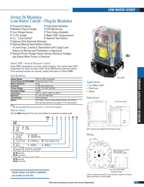
E-7Visit for most current information.XXXXX26MXX XX1. Series 26M2. SensitivityA – 4.7KB – 10KC – 26K3. Supply Voltage 1 – 120 VAC 3 – 24 VAC 8 – 208/240 VAC4. Socket StyleA – 11 Pin Octal5. Enclosure 0 – None6. Option PackageSee page D-36, Chart B for code letter.7. Time Delay (decreasing level) Option 03-90 seconds Blank 3 seconds8. Time Delay (increasing level) Option 00-90 seconds Blank 0 secondsD – 50K E– 100K 2 – 240 VAC 1 – NEMA 1 4 – NEMA 4B – DIN Mount M – None, Module Only W A R R I C K C O N D U C T I V I T Y S E N S O R SSeries 26 ModulesLow-Water Cutoff – Plug-In ModulesPowered Contacts Solid State Reliability Modular Plug-In Design LED Monitoring Low Voltage Sensor Time Delays Available 11-Pin Socket Meets CSD1 RequirementsU.L. “Limit Control” Optional Test Feature Optional Dirty Electrode Detection O ptional Manual Reset Button Feature.If Level Drops, Control is Deactivated Until Liquid Level Returns to Normal and Pushbutton is Depressed O ptional Power Outage Feature Ignores Nuisance Outages and Resets When Power is Restored Series 26M – General Purpose ControlSeries 26M is designed for low-water cutoff protection. This control meets CSD1 requirements for boiler low water cutoff. Series 26M features powered contacts. If non-powered contacts are required, request information on Series 26NM.SpecificationsContact Design 1 N.O. & 1 N.C. (powered)Contact Rating (24/120/240VAC) 10 amp Resistive 1/3 hp Mode of Operation Direct Sensitivity 0 - 26K ohm, factory set Primary Voltage 24 VAC, 120 VAC, 240 VAC 1Secondary Voltage 12 VAC Temperature -40°F to +150°F (-40°C to +65°C)Approvals 1U.L. 353 File # MP1430Terminal Style Screw connector Options Time Delays, Power Outage, Manual Reset, Test Feature, Dirty electrode detection; See page E-11 for descriptionsNotes:1. 240 VAC and 208/240 VAC units do not carry U.L. Limit Control recognition.Series 26MApplications• Low-Water Cutoff • Point Level • AlarmsDimensionsNote: Controls also available with DIN mount socket.WiringCaution: Contacts are powered. If non-powered contacts are required, request information on Series 26NM.Socket Details and Option Availability are located on web site.How to OrderUse the Bold characters from the chart below to construct a product code.E-10Visit for most current information.8-PIN OCTAL SOCKET1.14˝ (28.96 mm)0.625˝(15.9 m m )2˝(50.8 m m )2.31˝ (58.7 mm)1.66˝(42.16 m m)11-PIN OCTAL SOCKET1.3˝ (33.02 mm)0.625˝(15.88 m m )2.60˝ (66.04 mm)2.21˝(56.13 m m )2.53˝(64.26 m m )11-PIN DIN SOCKET 2.04˝ (51.82 mm)1.02˝(25.91 m m )2.33˝ (59.18 mm)1.0˝(2.54 m m )2.04˝ (51.82 m m )SocketsWarrick provides four different types of sockets for usewith plug-in control modules.1/16˝STANDOFFTOP VIEWSIDE VIEWBOTTOM VIEW1/8˝STANDOFFRETROFIT STANDOFFCIRCUIT BOARD STANDOFF SCREW MOUNT STANDOFFSockets and Standoffs – 16, 26 and DF Series OnlyStandoffsWarrick provides four different types of standoffs designed to connect circuit boards to panels.E-11Visit for most current information.W A R R I C K C O N D U C T I V I T Y S E N S O R SOptional Character Reference – 16, 26 and DF Series OnlyManual ResetAvailable on Series 26, 26M and DF controls(Normally closed pushbutton across reset terminals. Pushbutton ordered separately): Manual reset only applies to the function associated with terminal LLCO. When the liquid rises to the electrode on terminal LLCO, the control will remain de-energized (load contacts in original state) until the pushbutton is depressed. The control will then energize, (LED will be lit) changing the state of the contacts. The control remains energized until the liquid level recedes below electrode on terminal LLCO. The control then de-energizes, (LED will go off) returning load contacts to their original state. Unless otherwise specified, there is a three second time delay ondecreasing level. Liquid must be below probe on terminal LLCO for full three seconds before control de-energizes.Manual Reset with Power Outage FeatureAvailable on Series 26, 26M, and DF controlsReset (Normally closed pushbutton across reset terminals. Pushbutton ordered separately) Control will ignore power loss to control. With liquid in contact withelectrode on terminal LLCO, a power outage will cause the control to de-energize, but will automatically energize upon return of power. However, loss of liquid will cause control to de-energize and remain so until liquid again rises to electrode and pushbutton is depressed.Time Delays Associated with Terminals H and LAvailable on Series 16, 16M, and DF controlsWith time delay on increasing level, the liquid must be in contact with the highelectrode for the full duration of the time delay before control will operate. With delay on decreasing level, the liquid must be below the low electrode for the full duration of the time delay before control will operate. In single level service, terminals 3 and 4 must be jumpered together to achieve time delays on both increasing and decreasing levels or just decreasing level.Time Delays Associated with Terminal LLCOAvailable on Series 26, 26M, and DF controls3 Second time delay on decreasing level is standard. Delay up to 90 seconds, can be specified and would act in the same manner as listed above.Time Out OptionAvailable on Series 16, 16M, and DF controlsThe latching circuit for the high and low electrode has an optional timer. In some applications the High or Lowelectrode may become short circuited or disconnected. Such an occurrence may potentially over fill in fill applications, or cause the pump to run dry in pump down applications. The time option is custom programmed up to 3 minutes. When a fault condition occurs, the FILL LED will have a blink sequence of .5 seconds on 2 seconds off. See Chart A for time delay options.Test FeatureAvailable on Series 26, 26M, and DF controlsAllows LLCO circuit to be tested. Holding down the reset button for 3 seconds will allow the LLCO circuit to trip which simulates the loss of water, without the need of draining the water level in the boiler. The control will return to normal operation once the reset button is pressed a secondtime. (Test feature option only available with the manual reset function.)mounted by customer。
MF-25中文资料
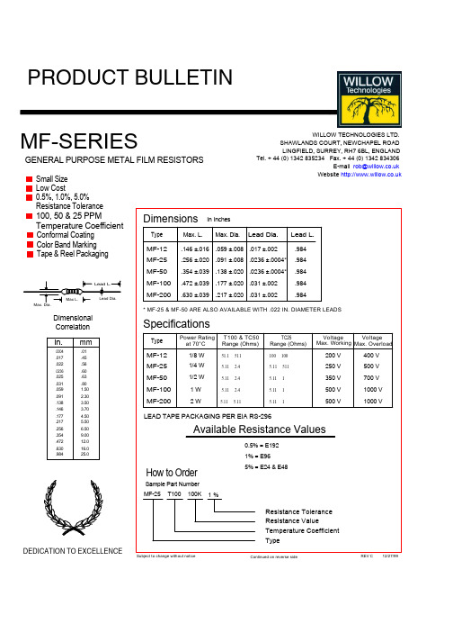
MF-SERIESGENERAL PURPOSE METAL FILM RESISTORS Small SizePRODUCT BULLETIN REV C12/27/99Continued on reverse sideWILLOW TECHNOLOGIES LTD.SHAWLANDS COURT, NEWCHAPEL ROAD LINGFIELD, SURREY, RH7 6BL, ENGLANDTel. + 44 (0) 1342 835234 Fax. + 44 (0) 1342 834306E-mail rob@ Website REV D 1/20/99Characteristic Specificati on Test Method(All resistance measurements should be performed after stabilization or conditioning periods.) DC RESISTANCE Within specifiedtolerance.MIL-STD-202Method 303 TEMPERATURE COEFFICIENT As buyer requested±25PPM/°C ±100PPM/°C ±50PPM/°C ±200PPM/°C MIL-STD-202 Method 304DIELECTRIC STRENGTHNo flashover or damageMIL-STD-202 Method 3011/8W 300V 1 minute 1/4W 500V 1 minute 1/2W 700V 1 minute 1, 2W 750V 1 minute INSULATION RESISTANCE At least 1000M ΩMIL-STD-202 Method 302 100V 1 minute CURRENT NOISE TEST 5.11Ω to 9.99Ω less than 0.05µV/V10Ω to 9.99K Ω less then 0.1µV/V 10K Ω to 1M Ω less then 0.2µV/V MIL-STD-202 Method 308VIBRATION∆R within ±(0.25% + 0.05Ω)MIL-STD-202 Method 201 10~ HzX.Y.Z. 3 directions 2 hours each. TERMINAL STRENGTHNo broken or loosened terminals.MIL-STD-202 Method 211 RESISTANCE TO SOLDERING HEAT ∆R within ±(0.25% + 0.05Ω) MIL-STD-202 Method 210350°C, 3 ±0.05 seconds SOLDERABILITY At least 95% coverage MIL-STD-202 Method 208230°C, 5 seconds THERMAL SHOCK∆R within ±(0.5% + 0.05Ω)MIL-STD-202 Method 107 -55°C, +155°C 5 cyclesSHORT TIME OVERLOAD ∆R within ±(0.05% + 0.05Ω)MIL-R-10509 Para, 4.6.62.5 times rated working voltage, 5 seconds HUMIDITY∆R within ±(1% + 0.05Ω) NO mechanical damage MIL-STD-202 Method 10340°C, RH 95% 500 LOW TEMPERATURE OPERATION ∆R within ±(0.5% + 0.05Ω)MIL-R-10509 Para 4.6.5 Rated workingvoltage, @ -65°C 45 minutes. LOAD LIFE∆R within ±(1% + 0.05Ω)MIL-STD-202 Method 108 Rated workingVoltage 1 ½ hours on. ½ hour off for total 1000 hours RESISTANCE TO SOLVENT Color bands legible. No mechanical damage.MIL-STD-202 Method 2151.00.320.100.0320.0100.003101001K10K100K1M0-10-20-30-40-50Nominal Resistance (Ω)u V/VdBCURRENT NOISE。
AIT1001非接触式红外测温模块 说明书
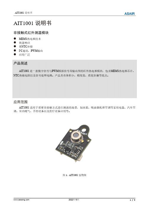
AIT1001说明书非接触式红外测温模块●MEMS热电堆技术●快速响应●带NTC补偿●I2C通讯,PWM输出●应用广泛产品简述AIT1001是一款数字信号与PWM模拟信号双输出型的红外热电堆模块,包含MEMS热电堆芯片、NTC热敏电阻以及信号处理电路。
产品具有体积小、精度高、质优价廉等优点。
应用范围AIT1001适用于需要非接触方式进行测温的场景,如冰箱、吸油烟机和空调等家用电器、汽车空调、室内暖气、手持设备以及医疗设备应用等。
图1.AIT1001实物图1.极限额定值表1.极限额定值2.性能参数及电气接口表2.模块性能参数表表3.电气接口说明注:上拉电阻的阻值推荐4.7kΩ。
AIT1001对应表3的电气接口如图2所示,其中端子规格为MX1.25-5PIN端子座。
图2.电气接口图3.产品尺寸图图3.产品尺寸图(单位:mm,公差:±0.3mm)4.通用寄存器表4.通用寄存器说明如需校准uValAdj或NtcAdj参数时,应将模块放置在与被测物体温度相同的环境中,根据如下条件进行校准:1、AIT1001模块输出的NTC温度应与环境温度相同,若偏差过大(>±0.5℃)可将修正值写入NtcAdj寄存器进行校准;2、热电堆电压uVal应在-15~+15µV内,若偏差过大可将修正值写入uValAdj寄存器进行校准。
发射率(Coef)是指被测物体表面辐射出的能量与相同温度的黑体辐射出的能量的比率。
不同的物体,其发射率亦有所不同,可根据实际使用需要进行修改。
5.I2C数字协议AIT1001遵循I2C总线规范,并需作为从机使用。
SCL为时钟输入线,SDA为串行数据输入/输出线。
表5.I2C通讯说明表6.I2C时序及CRC校验6.1读取模块数据的时序在一个I2C完整的Start-Stop读取模块数据通信中,每个寄存器数据后跟随一个对该寄存器数据的CRC校验字节,其CRC校验码字节的计算是对该寄存器数据字节进行CRC计算所得,如图4所示。
HTM2500LF温度与湿度传感器技术数据手册说明书

HTM2500LFTemperature and Relative Humidity ModuleSPECIFICATIONS∙ Hermetic Housing∙ Humidity calibrated within +/-2% @55%RH∙ Temperature measurement through NTC 10kOhms +/-1% direct output ∙ Small size product∙Typical 1 to 4 Volt DC output for 0 to 100%RH at 5VdcBased on the rugged HTS2035SMD humidity / temperature sensor, HTM2500LF is a dedicated humidity and temperature transducer designed for OEM applications where a reliable and accurate measurement is needed. Direct interface with a micro-controller is made possible with the module’s humidity linear voltage output.FEATURES∙ Full interchangeability∙ High reliability and long term stability ∙ Not affected by water immersion ∙ Ratiometric to voltage supply∙ Suitable for 3 to 10 Vdc supply voltageHumidity Sensor Specific Features∙ Instantaneous de-saturation after long periods in saturationphase∙ Fast response time∙ High resistance to chemicals ∙ Patented solid polymer structureTemperature Sensor Specific Features∙ Stable∙ High sensitivityAPPLICATIONS∙ Industrial∙ Process control ∙ Hygrostat ∙ Data loggerAPPLICATIONSPERFORMANCE SPECSELECTRICAL CHARACTERISTICS(Ta=25°C)TYPICAL PERFORMANCE CURVESHUMIDITY SENSORTypical response look-up table (Vs = 5V)Modeled linear voltage output (Vs = 5V)60708090250030003500Linear EquationsVout = 26.65 * RH + 1006RH = 0.0375 * Vout – 37.7with Vout in mV and RH in %Polynomial EquationsVout = 1.05E-3 *RH3 - 1.76E-1 *RH2 + 35.2 * RH + 898.6RH = -1.92E-9 *Vout3 + 1.44E-5 *Vout2 + 3.4E-3 *Vout – 12.4with Vout in mV and RH in %Measurement ConditionsHTM2500LF is specified for accurate measurements within 10 to 95% RH.Excursion out of this range (<10% or >95% RH, including condensation) does not affect the reliability of HTM2500LF characteristics.Error Budget at 23°CHTM2500LF Error Limits:Temperature coefficient compensation:HTM2500LF Linearity Error:Non-linearity and temperature compensation:with Vout in mV, RH in % and Ta in °C()()E T RH RH a read Cor 34.2231%%-⨯--⨯=HTM2500LF TEMPERATURE SENSOR: DIRECT NTC OUTPUT∙ Typical temperature outputDepending on the needed temperature measurement range and associated accuracy, we suggest two methods to access to the NTC resistance values.R T NTC resistance in Ω at temperature T in KR N NTC resistance in Ω at rated temperature T in K T, T N Temperature in K β Beta value, material specific constant of NTC e Base of natural logarithm (e=2.71828)① The exponential relation only roughly describes the actual characteristic of an NTC thermistor can, however, asthe material parameter β in reality also depend on temperature. So this approach is suitable for describing a restricted range around the rated temperature or resistance with sufficient accuracy.② For practical applications, a more precise description of the real R/T curve may be required. Either more complicated approaches (e.g. the Steinhart-Hart equation) are used or the resistance/temperature relation as given in tabulation form. The below table has been experimentally determined with utmost accuracy for temperature increments of 1 degree.Actual values may also be influenced by inherent self-heating properties of NTCs. Please refer to MEAS-France Application Note HPC106 “Low power NTC measurement”.∙ Temperature look-up table⎪⎪⎭⎫⎝⎛-⨯=N T T N T e R R 11β∙ Steinhart-Hart coefficientsAccording to the equation below, the Steinhart-Hart coefficients for the operating temperature range for HTM2500LF thermistor are:)ln(*)ln(*)ln(*)ln(*1R R R C R b a T++= R NTC resistance in Ω at temperature T in K T Temperature in K a Constant value (a = 8.54942E-04) b Constant value (b = 2.57305E-04) c Constant value (c = 1.65368E-07)∙ Temperature Interface CircuitConcerning the temperature sensor of the HTM2500LF, the following measuring method described below is based on a voltage bridge divider circuit. It uses only one resistor component (Rbatch) at 1% to design HTM2500LF temperature sensor interfacing circuit.Rbatch is chosen to be equal to NTC @25°C to get: Vout = Vcc/2 @25°C.The proposal method connects Rbatch to Vcc (5Vdc) and NTC to Ground. It leads to a negative slope characteristic (Pull-Up Configuration).W4NTC Resistance Vout (mV)W2 VCCRbatch 10k ΩW1 Ground)()()(*)()(25002500Ω+ΩΩ=LF HTM batch LF HTM OUT NTC R NTC mV Vcc mV VSUGGESTED APPLICATIONQUALIFICATION PROCESSRESISTANCE TO PHYSICAL AND CHEMICAL STRESSES∙ HTM2500LF has passed through qualification processes of MEAS-France including vibration, shock, storage, high temperature and humidity, ESD.∙ Additional tests under harsh chemical conditions demonstrate good operation in presence of salt atmosphere, SO2 (0.5%, H2S (0.5%), 03, NOx, NO, CO, CO2, Softener, Soap, Toluene, acids (H2SO4, HNO3, HCI), HMDS, Insecticide, Cigarette smoke, this is not an exhaustive list. ∙HTM2500LF is not light sensitive.SPECIFIC PRECAUTIONS∙ HTM2500LF is not protected against reversed polarity - Check carefully when connecting the device. ∙If you wish to use HTM2500LF in a chemical atmosphere not listed above, consult us.Steps of 1% RH are achievable by using 8-bit A/D.If more resolution is required, a 10-bit A/D needs to be used and a third display will be added, giving steps of 0.2% RH.PACKAGE OUTLINEHTM2500LF weight: 17.5g HTM2500LFL weight: 50gHTM2500LF wire characteristics: AWG 24 for W1, W2, W3 and W4 / AWG 16 for W5 HTM2500LFL wire characteristics: AWG 24 for W1, W2, W3 and W4 / AWG 16 for W5*Specific length available on requestFor operating temperature upper than 60°C, specific high temperature cable is required (1500mm long)ORDERING INFORMATIONHPP809A031 : HTM2500LFHUMIDITY VOLTAGE OUTPUT + NTC (TEMPERATURE DIRECT OUTPUT)HPP809A033 : HTM2500LFLHUMIDITY VOLTAGE OUTPUT + NTC (TEMPERATURE DIRECT OUTPUT) WITH LONG CABLE(MULTIPLE PACKAGE QUANTITY OF 10 PIECES)EUROPEMeasurement Specialties, Inc - MEAS FranceImpasse Jeanne BenozziCS 83 16331027 Toulouse Cedex 3FRANCETél: +33 (0)5 820 822 02Fax: +33(0)5 820 821 51Sales:****************************/sensorsolutionsMeasurement Specialties, Inc., a TE Connectivity company.Measurement Specialties, TE Connectivity, TE Connectivity (logo) and EVERY CONNECTION COUNTS are trademarks. All other logos, products and/or company names referred to herein might be trademarks of their respective owners.The information given herein, including drawings, illustrations and schematics which are intended for illustration purposes only, is believed to be reliable. However, TE Connectivity makes no warranties as to its accuracy or completeness and disclaims any liability in connection with its use. TE Connectivity‘s obligations shall only be as set forth in TE Connectivity‘s Standard Terms and Conditions of Sale for this product and in no case will TE Connectivity be liable for any incidental, indirect or consequential damages arising out of the sale, resale, use or misuse of the product. Users of TE Connectivity products should make their own evaluation to determine the suitability of each such product for the specific application.© 2015TE Connectivity Ltd. family of companies All Rights Reserved.。
Micro800 非隔离型热电偶功能性插件模块 产品目录号 2080-TC2 说明书

接线图Micro800™ 非隔离型热电偶功能性插件模块产品目录号2080-TC2/idc/groups/literature/documents/wd/208 0-wd006_-mu-p.pdfFR Cette publication est disponible en français sous forme électronique (fichier PDF).Pour la télécharger, rendez-vous sur la page Internet indiquée ci-dessus.IT Questa pubblicazione è disponibile in Italiano in formato PDF. Per scaricarla collegarsi al sito Web indicato sopra.DE Diese Publikation ist als PDF auf Deutsch verfügbar. Gehen Sie auf die oben genannte Web-Adresse, um nach der Publikation zu suchen und sie herunterzuladen.ES Esta publicación está disponible en español como PDF. Diríjase a la dirección web indicada arriba para buscar y descarga esta publicación.PT Esta publicação está disponível em portugués como PDF. Vá ao endereço web que aparece acima para encontrar e fazer download da publicação.ZHZC2 Micro800™ 非隔离型热电偶功能性插件模块出版物 2080-WD006A-ZH-P - 2010年9 月环境和机柜防止静电放电本设备适用于在污染等级 2 工业环境、过电压 II 类应用中使用 (如 IEC 60664-1 所定义),在海拔高达 2000 米 (6562 英尺) 时不降额。
细胞膜流动性的荧光检测方法
产品说明书
相关产品:
产品 Annexin V-FITC/PI 凋亡试剂盒 Annexin V-EGFP/PI 凋亡试剂盒 MTT 细胞增殖及毒性检测试剂盒 CCK-8 细胞增殖毒性检测试剂盒 WST-1 细胞增殖毒性检测试剂盒 MTS 细胞增殖与毒性检测试剂盒 Hoechst33342/PI 双染试剂盒 DAPI 染色试剂盒 细胞存活率检测试剂盒
-1-
咨询邮箱:bestbio@
电话:021-33921235
本产品仅供科学研究使用!请勿用于临床、诊断、食品、化妆品检测等用途!
产品说明书
感细胞明显增加。另有实验研究发现腹水癌细胞的恶性程度随着膜流动性的增加而增加,白 血病及转移的肿瘤细胞的膜流动性远远高于非转移细胞。因此,对敏感及耐药的肿瘤细胞膜 流动性的监测有着重要的意义。
注意事项: ● 本试剂盒仅供科学研究使用,不可用于诊断或治疗。 ● 螺旋盖微量试剂管装的试剂在开盖前请短暂离心,将盖和管内壁上的液体离心至管 底,避免开盖时试剂损失。 ● 样品或试剂被细菌或真菌污染或试剂交叉污染可能会导致错误的结果。 ● 最好使用一次性吸头、管、瓶或玻璃器皿,可重复使用的玻璃器皿必须在使用前清 洗并彻底清除残留清洁剂。 ● 避免皮肤或粘膜与试剂接触。 ● 染色液为 DMSO 溶液,冬季气温较低时在室温时为凝固状态,极易粘附在管壁、吸 头壁。注意需要加热溶解,吸头也需要放在培养箱预热,否者容易再次凝固在吸头 内壁产生损耗。 ● 荧光染料均存在淬灭问题,请尽量注意避光,以减缓荧光淬灭。
【CN110031365A】磁流变液壁滑效应检测装置【专利】

(19)中华人民共和国国家知识产权局(12)发明专利申请(10)申请公布号 (43)申请公布日 (21)申请号 201910196774.9(22)申请日 2019.03.03(71)申请人 浙江师范大学地址 321004 浙江省金华市婺城区迎宾大道688号浙江师范大学(72)发明人 高春甫 杨青形 贺新升 (51)Int.Cl.G01N 11/14(2006.01)(54)发明名称磁流变液壁滑效应检测装置(57)摘要本发明公开了一种磁流变液壁滑效应检测装置,包括升降板、固定剪切盘、第二线圈、线圈收纳筒、旋转剪切盘、第一线圈、固定板、扭矩传感器、侧板、导轨基座、底座和磁流变液变液,固定剪切盘固定连接于升降板上,旋转剪切盘转动连接于固定板上,扭矩传感器固定连接于侧板上,导轨基座固定连接于底座上,且导轨基座上设置有垂直升降驱动装置。
该磁流变液壁滑效应检测装置,可产生不同温度和磁场的复合物理场,实现对磁流变液的壁滑效应进行有效的检测,为高性能磁流变液的研制及应用提供保障。
权利要求书1页 说明书5页 附图7页CN 110031365 A 2019.07.19C N 110031365A权 利 要 求 书1/1页CN 110031365 A1.磁流变液壁滑效应检测装置,其特征在于:包括升降板、固定剪切盘、第二线圈、线圈收纳筒、旋转剪切盘、第一线圈和固定板,所述固定剪切盘中部轴向凸出有第一安装轴,所述旋转剪切盘中部轴向凸出有第二安装轴,所述第一线圈和第二线圈分别缠绕于所述线圈收纳筒,所述线圈收纳筒分别固定安装于所述升降板和所述固定板上,所述第一安装轴固定于升降板上,所述第二安装轴旋转连接于所述固定板上。
2.根据权利要求1所述的磁流变液壁滑效应检测装置,其特征在于:还包括导轨基座和底座,所述导轨基座焊接固定于所述底座,所述底座四角分别设置有支撑脚,所述升降板滑动连接于所述导轨基座上并由垂直升降驱动装置驱动进行上下直线往复运动。
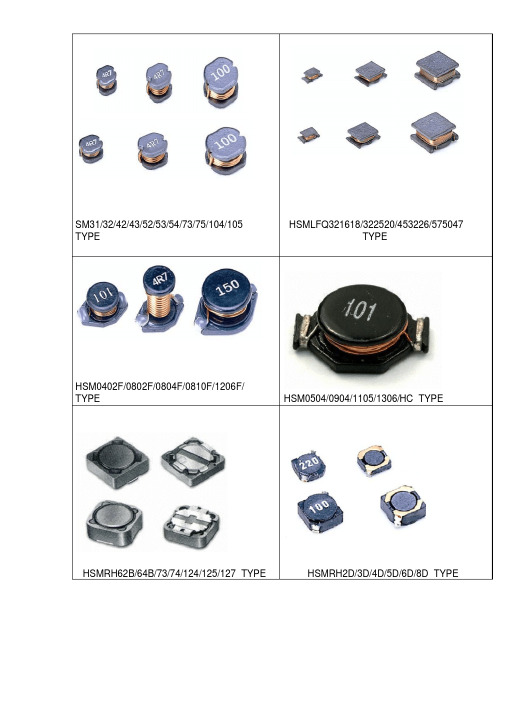
电感全型号尺寸封装
123-129
VC TYPE TC TYPE
130-133 134-141
HSMB TYPE
142-144
HSM TYRE
PART NUMBERING SYSTEM( 品名系列 )
HSM 54 -101 K –T/B
② ③ ①
② ③ ④ ⑤
①. 产品类型:产品代码。 ②. 产品尺寸:外围×高度。 ③. 电感值:前两位为有效值,第三位表零的个数。 ④. 电感公差 : J; 5℅, K: ±10℅,L: ±15℅,M: ±20℅,P: ±25℅,N: ± 30℅。 ⑤. 包装方式 : 〝T”: 载带盘装, B: 散装
±0.3 6.5
±0.3
9.5 1.5 3.7
HSM108
10.0±0.3 9.0
±0.3 8.3
±0.3
9.7 2.0 4.4
FEATURES( 特性 )
Various high power inductors are superior to be high saturation for surface mounting.
HSM42-2R7M 2.7
Equipments DC/DC Converters,etc
录放影机电源供应器 .液晶电视机 .笔记本电脑 .便携式通讯设备 .直流 /直流转换器
HSM31A/B TYPE
→电气性能 Electrical Characterisitics
PART NO. ( 品名 )
HSM31A-2R2M
INDUCTANCE(UH) 电感值
直流直流转换器parthsm31a350330021103351608hsm31b350330022003351608hsm32350330032003351608hsm424503400320034517515hsm434503400332034517515hsm52a5803520325035521517hsm52b5803520330035521517hsm53a5803520330035521517hsm53b5803520335035521517hsm545803520345035521517hsm73780370033503753020hsm75780370035003753020hsm10510003900354039537525hsm1061000390036503951537hsm1081000390038303972044hsm31abtype电气性能electricalcharacterisiticspart品名inductanceuh电感值dcr直流电阻maxidcamax最大耐电流l10testfreq测试频率hsm31a2r2m2203161khz025vhsm31a3r3m330351551khz025vhsm31a4r7m47041471khz025vhsm31a6r8m68051341khz025vhsm31a100m100061241khz025vhsm31a150m1500751221khz025vhsm31a220m2201051091khz025vhsm31a470m470250961khz025vhsm31b1r0m100052251khz025vhsm31b1r5m150065201khz025vhsm31b2r2m220067121khz025vhsm31b3r3m330271081khz025vhsm31b3r9m390831001khz025vhsm31b4r7m4711311001khz025vhsm31b5r6m561250801khz025vhsm31b8r2m821000581khz025vhsm31b100m100270751khz025vhsm31b120m120520761khz025vhsm31b150m15091051khz025vhsm31b180m181750401khz025vhsm31b220m221900351khz025vhsm31