压力开关调整61
电压力锅压力开关工作原理

电压力锅压力开关工作原理
电压力锅压力开关是一种安全阀门,可以监测和控制内部蒸气压力,确保锅内压力维持在安全范围内。
它的工作原理如下:
1. 压力感应器:压力开关的关键组件是压力感应器,通常由弹簧和薄膜构成。
当锅内压力升高时,锅内的蒸气会作用在压力感应器上,使得弹簧和薄膜发生变形。
2. 开关机构:压力感应器的变形将传导给开关机构,触发开关机构的动作。
开关机构通常由触发杆和控制阀组成。
当压力感应器变形时,触发杆会被推动,进而控制阀也会发生位移。
3. 控制阀:控制阀的主要作用是控制锅内蒸气的排放。
当锅内压力升高时,控制阀会打开,允许一部分蒸气释放,以减缓压力的上升。
当压力感应器恢复原状时,控制阀会关闭,停止蒸气的排放。
4. 压力释放及封闭:压力开关通过控制阀的开关动作,实现了锅内压力的自动调节。
当压力太高时,压力开关会打开控制阀,释放部分蒸气,直到压力降至安全范围内;当压力降低到设定值以下时,压力开关会关闭控制阀,封闭锅内蒸气排放口。
通过以上工作原理,电压力锅压力开关能够保证内部压力始终在安全范围内,有效避免了过高压力可能导致的危险。
压力开关调节方法
压力开关调节方法压力开关是一种用于控制压缩机启停的重要设备,它能够根据系统压力的变化来控制压缩机的运行,从而保证系统的正常运行并避免过载。
正确的调节压力开关对于系统的稳定运行至关重要。
下面将介绍一些常见的压力开关调节方法,希望能对大家有所帮助。
首先,调节压力开关之前需要确保系统处于安全状态,压缩机已经停机并且系统压力已经完全释放。
接下来,可以按照以下步骤进行调节:1. 确定压力开关的工作范围,根据压力开关的规格和系统的工作要求,确定压力开关的工作范围。
通常情况下,压力开关会有一个最小压力和最大压力范围,需要根据实际情况来进行调节。
2. 调节压力开关的切换压力,使用专用的调节工具,可以逐步调节压力开关的切换压力。
在调节过程中,需要不断地监测系统的压力变化,并根据需要进行微调,直到达到所需的切换压力为止。
3. 调节差动压力,有些压力开关还具有差动压力的调节功能,可以通过调节差动压力来控制压缩机的启停频率。
在调节差动压力时,需要根据系统的实际工作情况来确定最佳的差动压力数值。
4. 测试和确认,在完成压力开关的调节之后,需要对系统进行测试,确保压力开关能够准确地控制压缩机的启停,并且系统的压力稳定在设定的范围内。
如果测试结果不理想,需要重新进行调节,直到达到预期的效果为止。
需要注意的是,在进行压力开关的调节过程中,一定要小心谨慎,避免造成系统的损坏或者安全事故。
另外,建议定期对压力开关进行检查和维护,确保其工作正常可靠。
总之,正确的调节压力开关对于系统的稳定运行至关重要。
通过以上介绍的调节方法,相信大家能够更好地掌握压力开关的调节技巧,保证系统的正常运行和安全性。
希望本文对大家有所帮助,谢谢阅读!。
压力开关·流量开关共同注意事项
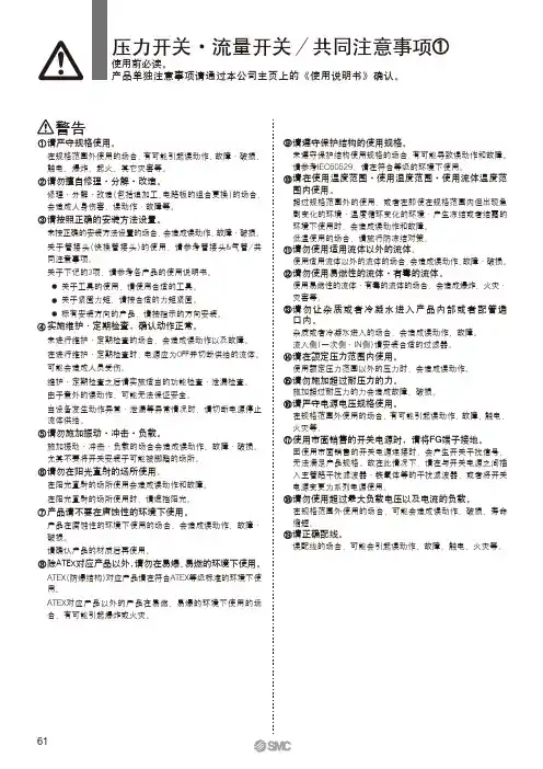
警告请严守规格使用。
在规格范围外使用的场合,有可能引起误动作、故障·破损、触电、爆炸、起火、其它灾害等。
请勿擅自修理·分解·改造。
修理·分解·改造(包括追加工、电路板的组合更换)的场合,会造成人身伤害、误动作·故障等。
请按照正确的安装方法设置。
未按正确的安装方法设置的场合,会造成误动作、故障·破损。
关于管接头(快换管接头)的使用,请参考管接头&气管/共同注意事项。
关于下记的3项,请参考各产品的使用说明书。
● 关于工具的使用,请使用合适的工具。
● 关于紧固力矩,请按合适的力矩紧固。
● 标有安装方向的产品,请按指示的方向安装。
实施维护·定期检查,确认动作正常。
未进行维护·定期检查的场合,会造成误动作以及故障。
在进行维护·定期检查时,电源应为OFF并切断供给的流体。
可能会造成人员受伤。
维护·定期检查之后请实施适当的功能检查·泄漏检查。
由于意外的误动作,可能无法保证安全。
当设备发生动作异常·泄漏等异常情况时,请切断电源停止流体供给。
请勿施加振动·冲击·负载。
施加振动·冲击·负载的场合会造成误动作、故障·破损。
尤其不要将开关安装于可能被脚踏的场所。
请勿在阳光直射的场所使用。
在阳光直射的场所使用会造成误动作和故障。
在阳光直射的场所使用时,请遮挡阳光。
产品请不要在腐蚀性的环境下使用。
产品在腐蚀性的环境下使用的场合,会造成误动作、故障·破损。
请确认产品的材质后再使用。
除ATEX对应产品以外,请勿在易爆、易燃的环境下使用。
ATEX(防爆结构)对应产品请在符合ATEX等级标准的环境下使用。
ATEX对应产品以外的产品在易燃、易爆的环境下使用的场合,有可能引起爆炸或火灾。
请遵守保护结构的使用规格。
未遵守保护结构使用规格的场合,有可能导致误动作和故障。
霍尼韦尔C6097A,B压力开关说明书
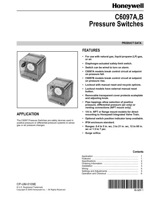
PRODUCT DATA65-0237-1CP-UM-5109E® U.S. Registered TrademarkCopyright © 2000 Honeywell Inc. • All Rights ReservedC6097A,BPressure SwitchesAPPLICATIONThe C6097 Pressure Switches are safety devices used in positive-pressure or differential-pressure systems to sense gas or air pressure changes.FEATURES•For use with natural gas, liquid propane (LP) gas, or air.•Diaphragm-actuated safety-limit switch.•Switch can be wired to turn on alarm.•C6097A models break control circuit at setpoint on pressure fall.•C6097B models break control circuit at setpoint on pressure rise.•Lockout with manual reset and recycle options.•Lockout models have external manual reset button.•Removable transparent cover protects scaleplate and adjusting knob.•Pipe tappings allow selection of positive pressure, differential pressure (air only) or venting connections (NPT mount only).•1/4 in. NPT or flange mount models for direct mounting to Honeywell Integrated Valve Train.•Optional switch position indicator lamp available.•IP54 enclosure standard.•Ranges: 0.4 to 5 in. wc, 3 to 21 in. wc, 12 to 60 in. wc or 1.5 to 7 psi.•Surge orifice.ContentsApplication ........................................................................1Features ...........................................................................1Specifications ...................................................................2Ordering Information ........................................................2Installation ........................................................................4Wiring ...............................................................................5Settings and Adjustments .................................................5Operation and Checkout ..................................................6C6097A,B PRESSURE SWITCHES65-0237—12ORDERING INFORMATIONWhen purchasing replacement and modernization products from your TRADELINE® wholesaler or distributor, refer to theTRADELINE® Catalog or price sheets for complete ordering number.If you have additional questions, need further information, or would like to comment on our products or services, please write or phone:1.Your local Home and Building Control Sales Office (check white pages of your phone directory).2.Home and Building Control Customer Logistics Honeywell Inc., 1885 Douglas Drive NorthMinneapolis, Minnesota 55422-4386 (612) 951-1000In Canada—Honeywell Limited/Honeywell Limitée, 155 Gordon Baker Road, North York, Ontario M2H 3N7.International Sales and Service Offices in all principal cities of the world. Manufacturing in Australia, Canada, Finland, France, Germany, Japan, Mexico, Netherlands, Spain, Taiwan, United Kingdom, U.S.A.SPECIFICATIONSModels:C6097A Pressure Switch: Breaks a circuit when pressure falls to scale setting. See Table 1.C6097B Pressure Switch: Breaks a circuit when pressure rises to scale setting. See Table 1.Table 2 shows switch ratings and Table 3 shows alternate electrical ratings when used with Honeywell Flame Safeguard Programmers.Minimum Ambient Temperature: -40°F (-40°C).Maximum Ambient Temperature: 140°F (60°C).Connections (Depending on Model):1/4-18 NPT tapping for main or high-pressure connection.1/8-27 NPT tapping for vent or low-pressure connection (air only).Flange mount for connection to Honeywell Integrated Valve Train (internal vent only, no external connections).Scale Range:0.4 to 5 in. wc (0.10 kPa to 1.25 kPa).3 to 21 in. wc (0.75 to 5.23 kPa).12 to 60 in. wc (3.0 kPa to 15 kPa).1.5 to 7 psi (10.3 kPa to 48 kPa).Approvals:Underwriters Laboratories Inc. listed.Canadian Standards Association listed.Factory Mutual: Approved.Industrial Risk Insurers: Acceptable.CSD-1 AFB: Acceptable.Accessories:32003041-001 C6097 Cover for manual reset models.32003040-001 C6097 Cover for recycle models.32003039-001 Position Indication Lamp Kit.Dimensions: See Fig. 1 and 2.Fig. 1. C6097 1/4 in. NPT Mount dimensions in in. (mm).C6097A,B PRESSURE SWITCHES365-0237—1a Acceptable media: Natural gas, liquid propane (LP) gas, and air .Table 1. Pressure Switch Model Selection.Model Operating Pressure Range Manual Reset DifferentialNon-Manual ResetDifferentialDifferential Type Maximum Rated Pressure(continuous) (psi)Manual Reset Media a Switch Action at Setpoint Comments Maximumat Minimum Setpoint Maximumat MaximumSetpoint Nominal Maximum C6097A10040.4 to 5 in. wc——0.16 in. wc 0.24 in. wc Additive2.9 No Air/Gas Breaks N.O. to C.connection on pressure fall.1/4 in. NPT Mount C6097A1012 3 to 21 in. wc2.4 in. wc 4.2 in. wc —— 4.3Yes Air/Gas 1/4 in. NPT Mount C6097A1020 3 to 21 in. wc 2.4 in. wc 4.2 in. wc —— 4.3Yes Air/Gas Flange Mount C6097A103812 to 60 in. wc 10 in. wc 12 in. wc —— 4.8Yes Air/Gas 1/4 in. NPT Mount C6097A104612 to 60 in. wc10 in. wc12 in. wc—— 4.8Yes Air/Gas Flange Mount C6097A1053 3 to 21 in. wc—0.24 in. wc0.48 in. wc 4.3No Air/Gas 1/4 in. NPT Mount C6097A1061 3 to 21 in. wc ——0.24 in. wc0.48 in. wc4.3No Air/Gas Flange Mount C6097A107912 to 60 in. wc —— 1.1 in. wc 2.4 in. wc 4.8No Air/Gas 1/4 in. NPT Mount C6097A108712 to 60 in. wc—— 1.1 in. wc 2.4 in. wc 4.8No Air/Gas Flange Mount C6097A10950.4 to 5 in. wc 0.6 in. wc 1.0 in. wc —— 2.9Yes Air/Gas 1/4 in. NPT Mount C6097A1103 1.5 to 7 psi 1.1 psi 1.4 psi ——9.3Yes Air/Gas Flange Mount C6097A1111 1.5 to 7 psi 1.1 psi 1.4 psi ——9.3Yes Air/Gas 14 in. NPT Mount C6097A1129 1.5 to 7 psi ——0.1 psi 0.39.3No Air/Gas Flange Mount C6097A1137 1.5 to 7 psi——0.1 psi 0.39.3No Air/Gas 1/4 in. NPT Mount C6097A12100.4 to 5 in. wc——0.16 in. wc 0.24 in. wc 2.9No Air/Gas Flange Mount C6097A12280.4 to 5 in. wc ———— 2.9Yes Air/Gas Flange MountC6097B100212 to 60 in. wc 10 in. wc 12 in. wc ——Subtractive4.8Yes Air/Gas Breaks N.C. to C. connectionon pressure rise.1/4 in. NPT Mount C6097B101012 to 60 in. wc10 in. wc12 in. wc —— 4.8Yes Air/Gas Flange Mount C6097B1028 3 to 21 in. wc2.4 in. wc 4.2 in. wc —— 4.3Yes Air/Gas 1/4 in. NPT MountC6097B1036 3 to 21 in. wc 2.4 in. wc 4.2 in. wc —— 4.3Yes Air/Gas Flange Mount C6097B1044 1.5 to 7 psi 1.1 psi 1.4 psi ——21.0Yes Air/Gas Flange Mount C6097B1051 1.5 to 7 psi1.1 psi1.4 psi ——21.0Yes Air/Gas 1/4 in. NPT Mount C6097B1069 3 to 21 in. wc ——0.24 in. wc0.48 in. wc4.3No Air/Gas Flange Mount C6097B107712 to 60 in. wc —— 1.1 in. wc 2.4 in. wc 4.8No Air/Gas Flange Mount C6097B108512 to 60 in. wc —— 1.1 in. wc 2.4 in. wc 4.8No Air/Gas 1/4 in. NPT Mount C6097B1093 1.5 to 7 psi ——0.1 psi 0.3 psi 21.0No Air/Gas Flange Mount C6097B1101 1.5 to 7 psi——0.1 psi 0.3 psi 21.0No Air/Gas 1/4 in. NPT Mount C6097B11193 to 21 in. wc——0.24 in. wc0.48 in. wc4.3NoAir/Gas1/4 in. NPT MountC6097A,B PRESSURE SWITCHES65-0237—14Table 2. Switch Ratings (Amperes)Table 3. Alternate Electrical Ratings when used withHoneywell Flame Safeguard Programmers.Fig. 2. C6097 Flange Mount dimensions in in. (mm).INSTALLATIONWARNINGExplosion or Fire Hazard.Can cause severe personal injury, death or property damage.Observe all safety requirements each time a control is installed on a burner.When Installing this Product...1.Read these instructions carefully. Failure to follow them can damage the product or cause a hazardous condition.2.Check the ratings given in the instructions and on the product to make sure that the product is suitable for your application.3.Installer must be a trained, experienced service technician.4.After installation is completed, check out product operation as provided in these instructions.WARNINGElectrical Shock Hazard.Can cause serious personal injury or death.Disconnect power supply before beginning installation. More than one disconnection can be involved.MountingNOTE:On flange models, remove the label holding theO-ring in place and make sure O-ring seal is in place before mounting the pressure switch on the valve.The C6097 models allow NPT or flange (directly to valve) mounting. The NPT models have a hexagonal fitting with a 1/4 in. NPT tapping, which is the high pressure connection, in differential applications. The bleed fitting is 1/8 in. NPTtapped. In differential pressure control applications using air only, connect the lower pressure to the bleed fitting. See Fig. 1 and Table 1. In applications using combustible gases, vent the bleed tapping according to applicable standard code or jurisdictional authority.C6097 models with flange mount can be fitted directly toHoneywell Integrated Valve Train (model specific). See Fig. 2 and Table 1. The flange mount models vent internally, with no external tap.Mount the C6097A,B in any position.Leak CheckAfter installation, perform a leak check on the pressure switch:1.Turn on main gas. Make sure gas has reached thepressure switch (e.g., high gas pressure switch)2.Check installation for gas leaks using a gas leak detector or a soap solution.120/240 Vac, 50/60 HzInductive Full Load 3.0Locked Rotor18.0Resistive5.0DeviceRatingIgnition Transformer 540 VA Pilot Valve 50 VAMain Valve400 VA with 2-1/2 times inrush.C6097A,B PRESSURE SWITCHES565-0237—1WIRINGWARNINGElectrical Shock Hazard.Can cause serious personal injury or death.Disconnect power supply before beginning installation. More than one disconnection can be involved.Make sure that all wiring agrees with all applicable localcodes, ordinances and regulations. An opening is provided to accommodate rigid conduit or armored cable for line voltage operation (see Fig. 3 and 4). Do not overload the switch contacts (see Switch Ratings in the Specifications section). The switching schematic is shown in Fig. 5.Fig. 3. C6097 (manual reset switch model)with cover removed.Fig. 4. C6097 (recycle model) with cover removed.SETTINGS AND ADJUSTMENTSPressure Setpoint Adjustmentdial (Fig. 3, 4 and 5) clockwiseto decrease the pressure setting.Fig. 5. C6097 schematic.C6097A,B PRESSURE SWITCHES65-0237—16OPERATION AND CHECKOUTOperationThe manual reset C6097A diaphragm actuates the snap-acting switch to break a control circuit and lock out when pressure falls to the scale setting. The recycle C6097Amodels recycle automatically when the control circuit returns to scale setting plus differential.The manual reset C6097B diaphragm actuates the snap-acting switch that breaks a control circuit and locks out when the pressure rises to the scale setting. The recycle C6097B models recycle automatically when the control pressure falls to the scale setting minus differential.Manual ResettingThe C6097A manual reset models lock out when pressure falls to the scale setting and require manual resetting after the pressure rises to scale setting plus differential to resume normal operation.The C6097B manual reset models lock out when pressure rises to the scale setting and require manual resetting after the pressure falls to scale setting minus the differential to resume normal operation.To reset, once normal operating pressure is restored, push the reset button in as far as it goes, then release.IMPORTANTLockout models cannot be made to recycleautomatically by permanently holding in the reset lever.CheckoutC6097 Gas Fuel Application1.Set cutoff pressure.2.Open main supply line. Depress reset lever on lockout models until switch makes control circuit.3.Set controller and limit switch to call for heat.4.For C6097A: Close the manual gas shutoff valve. C6097 should open control circuit when pressure reaches cutoff point.For C6097B: Open the manual gas shutoff valve, wait a few minutes for the pressure to rise; then lower the scale setting until the switch breaks control circuit and locks out.5.For C6097A: Open the shutoff valve, return thepressure switch to its original setting and press the reset button (if necessary).For C6097B: raise setting to normal and press reset button (if necessary).6.Allow system to operate through at least one complete cycle to make sure all components are functioning properly.C6097A Air Application1.Set cutoff pressure.2.Turn on fan.3.Block fan inlet or filter area. Switch should break control circuit when pressure drops to cutoff point. Manual reset models lock out.4.Remove obstruction. Press reset lever (manual reset models) and allow system to operate through at least one complete cycle to be sure all components are functioning properly.765-0237—165-0237—1 G.R. Rev. 4-00Home and Building Control Home and Building ControlHoneywell Asia Pacific Inc.Honeywell Inc.Honeywell Limited-Honeywell Limitée Room 3213-3225Honeywell Plaza 155 Gordon Baker Road Sun Hung Kai Centre P.O. Box 524North York, Ontario No. 30 Harbour Road Minneapolis, MN 55408-0524M2H 3N7Wanchai Hong KongHoneywell Latin American Region Honeywell Europe S.A.480 Sawgrass Corporate Parkway 3 Avenue du Bourget Suite 2001140 Brussels Sunrise FL 33325Belgium。
ZSE40F(SMC数显压力开关)手册
文件No.PS※※-OMM0006-A 使用说明书产 品 名 称数字式压力开关型式/系列/型号ZSE40A(F)ISE40A目录安全注意事项 2 型式表示・型号体系 9 产品各部品名称及功能 11 用语的定义及用语集 12 安装・设置 15 设置方法 15 配管方法 17 配线方法 19 压力设定 21 什么是设定模式 21 功能设定 23 什么是功能选择模式 23 出厂设定 23 F0 单位切换功能 25 F1 OUT1的设定 26 F2 OUT2的设定 29 F3 响应时间的设定 31 F4 自动预设功能的设定 32 F5 模拟输出/自动移位输入的设定 34 F6 显示值微调整的设定 36 F11 分辨率的设定 37 F80 省电模式的设定 38 F81密码输入的设定 39 特殊功能的设定 40 F90 全功能的设定 40 F97 复制功能的选择 42 F98 输出确认 44 F99 恢复出厂设置 46 其他设定 47 维护 50 忘记密码的情况 51 故障的消除 52 规格 59 规格表 59 外形尺寸图 61安全注意事项这里所示的注意事项是为了能安全正确的使用本产品,预先防止对您和他人造成危害或损失。
为了表示这些事项的危险程度,将注意事项分成「注意」「警告」和「危险」三个等级。
请您也遵守和安全相关的其他重要内容,如国际规格(ISO/IEC)、日本工业规格(JIS)※1以及其他安全法规※2。
*1) ISO 4414: Pneumatic fluid power -- General rules relating to systemsISO 4413: Hydraulic fluid power -- General rules relating to systemsIEC 60204-1: Safety of machinery -- Electrical equipment of machines (Part 1: General requirements) ISO 10218-1: Robots for industrial environments—Safety requirements –Part 1: RobotJIS B 8370: 空气压系统通则JIS B 8361: 油压系统通则JIS B 9960-1: 机械类的安全性-机械的电气装置(第1部:一般要求事项)JIS B 8433-1: 工业机器人- 安全要求事项-第1部: 机器人等*2) 劳动安全卫生法 等注意: 错误操作时,人和设备可能受到损伤的事项。
自动复位压力控制器说明书
自动复位压力控制器说明书
压力控制器是工业过程测量与控制系统中控制压力的一种专用仪表,工程中通常称作压力开关。
设定值为上切换值的调整方法
选用设定范围在(0.05~2.5)MPa的控制器,要求上限切换值为2.0MPa。
1、松开锁紧器,将控制器旋入校验台的螺纹接口上;打开盖板,将电缆穿过电缆接口接入端子板,电缆另一头接上万用表;
2、加压至2.0MPa,此值可由标准压力表读出;顺时针转动设定值调节镙杆,使设定值由大变小,直至微动开关在2.0MPa处切换。
3、旋动锁紧器,调节校验台压力,使其在2.0MPa上下来回变化,校验压力上升时,切换值是否为2.0MPa,此值即为要求设定的上切换值,此值减去切换差(约0.085MPa)即为下切换值。
设定值为下切换值的调整方法
同样选用设定范围在(0.05~2.5)MPa的控制器,但要求压力下降至1.8MPa(此值为下切换值)发出触点信号。
1、松开锁紧器,将控制器旋入校验台的螺纹接口上;打开盖板,将电缆穿过电缆接口接入端子板,电缆另一头接上万用表。
2、加压至1.8MPa,此值可由标准压力表读出;逆时针转动设定值调节镙杆,使设定值由小变大,直至微动开关在1.8MPa处切换。
3、旋动锁紧器,调节校验台压力,使其在1.8MPa处上下来回变化,校验压力下降时,切换值是否为1.8MPa,此值即为要求设定
的下切换值,此值加上切换差(约0.85MPa)即为上切换值。
SMC压力开关是怎么调试开关的
SMC压力开关|是怎么调试开关的
想要了解SMC压力开关的调试方法,应该从哪些方面入手呢,首先了解什么是SMC开关,SMC开关压力值有哪些变化,要安装压力表,是为了观察电阻输出的电流,为了后面的电阻接触方法的调整,在遇到导电性的问题,应该检查电阻和绕组之间的导电性是不是良好的。
1、在SMC磁性压力开关校正器上安装压力表,并将可变电阻附着在表上,以欧姆表或万用表。
然后,通过正向测试和反向测试来验证压力表的压力指示器,该指标的误差应符合验证程序的要求。
在欧姆龙或万用表中观察到可变电阻值的变化。
当观察时,必须注意电阻值的输出值得大小,(这其中对带电触点信号装置的SMC压力型号表信号的错误读数相同。
)电阻变化与压力指示器相同,应该是连续性的,并注意其连续性。
在压力指示器的上下限制的要求,要注意可变电阻是否在有效的工作范围内,或者需要通过改变接触方法来调整。
2、检查可变电阻和绕组压力开关的,电阻之间的导电性能是否良好,因为它与连接电路的功能是否直接相关,检查接触点与绕组电阻之间的接触压力,不宜过小,也不轻松接触,如轻松接触通过改变触板形状的方法,检查接触点与绕组与电阻之间的接触压力,其反应过大,两者不能接触太紧,还有,如果接触太紧密的话,在这样的环境下用棉签在酒精清洁移动接触片的接电触层。
此外,接触压力的增加也可以减少接触电阻的压力。
这样做的目的减少接触SMC压力的增加,增加工作效率,减少失误,是因为要控制压力指示器值的范围,调整更好的接触方法,如果这种方法能够帮助到你,那就快点行动吧!。
SCHMIDT说明书
液压缸结构图1:结构1 液压缸 5 重力调节2 压力头 6 框架3 滑枕7 H框架4 固定盘图2 :功能原理1 气源接口 5 工作活塞2 气源接口 6 气源接口3 进给活塞7 冲头4 气源接口8 传动活塞快速进气冲程在快速进气冲程中,气源接口依靠压缩空气进行增压。
气源接口(1)和(6)是泄压端口。
工作活塞(5)和进给活塞(3)依靠很低的压力移动,直到冲头(7)遇到阻力为止。
动力冲程当冲头(7)遇到阻力时,一个阀将压缩空气从接口(2)转换到转换到接口(1),传动活塞(6)向下移动。
这样做,可以将液压接口从进给活塞(3)和工作活塞(5)之间分开。
冲头(7)随着压力增大而向下运动。
反冲程在反冲程中,接口(1)和(4)处于泄压状态,接口(2)和(6)在压缩空气的作用下进行增压。
工作活塞(5)和传动活塞(6)同时往回运动。
当工作活塞和进给活塞中间的液压接口重新打开后,进给活塞在油压运动回到原点的压力作用下而增压。
2.2 气动块(可调节性的)单通道控制块结构图3 单通道气动控制块(示例)1 开关阀(K1) 5 压力表2 压力开关(B2) 6 压缩气源接口(1)3 电磁阀(K2)7 过滤减压阀(FDM)4 消音器功能单通道气动控制块通过压缩气源接口(1)接到压缩气源上。
过滤减压阀(FDM)是用来脱水、清洁压缩空气(过滤孔径40μm),以及预选一个启动压力,大约3~6 bar。
如果想要进一步降低压力,可以选择一个输出力预选器(大约可调至1 bar)。
开关阀(K1)通过连接控制单元来控制开关。
压力开关(B2)是用来监控主要压力。
当主要压力降低至一个固定值时,控制单元就会关闭。
电磁阀(K2)是用来激励工作冲程和反冲程的。
其他的启动控制元件可以从封闭式气动平面图中看出来,例如一些特定的重型工具中,其冲头在原点位置上用来设置冲程速度的单相流量控制阀或用来止逆的辅助/导频控制单向阀。
双通道安全模块结构图4 双通道气动控制块(示例)1 开关阀8 顺序阀2 输出力预选器9 消音器3 原点开关(B5)10 压力开关(B2)4 原点开关(B6)11 压缩气体端口5 电磁阀(K2)12 压力表6 电磁阀(K3)13 过滤减压阀(FDM)7 封板功能单通道气动控制块通过压缩气源接口(1)接到压缩气源上。
数字式压力开关 ZSE20A(F) ISE20A 使用说明书
文件No.PS※※-OMU0002CN-D数字式压力开关ZSE20A(F)ISE20A安全注意事项 2型式表示・型号体系 8产品各部分名称及功能 10用语说明 11安装·设置 15设置方法 15配管方法 17配线方法 19设定概要[测量模式] 22压力的设定 23 3步设定模式 24简单设定模式 26功能选择模式 28功能选择模式 28出厂时的设定 28 F0 单位切换功能 30 F1 OUT1的设定 31 F2 OUT2的设定 34 F3 数字滤波器的设定 36 F4 自动预设功能的设定 37 F5 FUNC端子的设定 39 F6 显示值微调的设定 41 F10 子画面的设定 42 F11 显示分辨率的设定 48 F80 省电模式的设定 49 F81 密码输入的设定 50 F82 线名输入的设定 52 F90 全功能的设定 53 F96 输入信号确认 55 F97 复制功能的选择 56 F98 输出确认 58 F99 恢复出厂设置 60其他设定 61维护 65忘记密码的场合 65故障一览表 66规格 75规格表 75外形尺寸图 78安全注意事项此处所示的注意事项是为了确保您能安全正确地使用本产品,预先防止对您和他人造成危害和伤害而制定的。
这些注意事项,按照危害和损伤的大小及紧急程度分为“注意”“警告”“危险”三个等级。
无论哪个等级都是与安全相关的重要内容,所以除了遵守国际标准(ISO/IEC)、日本工业标准(JIS)*1) 以及其他安全法规*2)外,这些内容也请务必遵守。
*1) ISO 4414: Pneumatic fluid power -- General rules relating to systemsISO 4413: Hydraulic fluid power -- General rules relating to systemsIEC 60204-1: Safety of machinery -- Electrical equipment of machines (Part 1: General requirements)ISO 10218: Manipulating industrial robots-SafetyJIS B 8370: 空气压系统通则JIS B 8361: 油压系统通则JIS B 9960-1: 机械类的安全性‐机械的电气装置(第1部: 一般要求事项)JIS B 8433: 产业用操作机器人-安全性等*2) 劳动安全卫生法 等安全注意事项本产品适用于下述“保证以及免责事项”、“适合用途的条件”。
auto reset压力开关说明书
auto reset压力开关说明书
1、(ON/OFF)运行键:系统运行键,进行参数设置必须关闭运行键,否则设置无法进行。
2、(SET)设置键:短按此按键进入压力上下限设置状态,长按3秒进入系统设置状态。
3、增加键(▲):按键一次数字增加0.01MP,长按2秒后数字增加0.1MPa。
4、减小键(▼):按键一次数字减小0.01MP,长按2秒后数字减小0.1MPa。
设置控制压力的方法
(1)短按(ON/OFF)运行键,关闭运行指示灯,压力控制系统关闭。
(2)设置控制上限/下限
短按SET键1次,进入下限设置状态(对应下限指示灯亮),通过(▲)(▼)设置数值,设置下限完成后,短按SET键进入上限设置,设置方法同上。
(3)设置完成后,按SET键将设定值自动存入电脑芯片(参数修改后,5秒钟内无按键操作会自动保存当前参数设置)。
(4)再次按(ON/OFF)运行键(对应运行指示灯亮),电机开始工作。
单位切换方法
短按(ON/OFF)运行键,关闭运行指示灯,短按增加键(▲)可以将单位在MPa、Kg/cm、PSI 之间任意切换。
设置完成后开启运行指示灯。
零位清零功能
短按(ON/OFF)运行键,关闭运行指示灯,长按减小键(▼)5秒可以将当前压力值清零,修正零位误差。
设置完成后开启运行指示灯。
(使用此功能时压力开关不得施加压力。
)。
- 1、下载文档前请自行甄别文档内容的完整性,平台不提供额外的编辑、内容补充、找答案等附加服务。
- 2、"仅部分预览"的文档,不可在线预览部分如存在完整性等问题,可反馈申请退款(可完整预览的文档不适用该条件!)。
- 3、如文档侵犯您的权益,请联系客服反馈,我们会尽快为您处理(人工客服工作时间:9:00-18:30)。
1. Please remove the cover.
2. Please loosen lock screw bolt-ⓐ first.
3. Adjusting the range spindle-ⓑ.
4. Please set scale-ⓒ at 20bar for starting then, the red line on the scale-ⓒ can * Turn in clockwise - setting pressure is value by adjusting the range spindle-ⓑ.
be adjusted by the range spindle-ⓑ.
go up.
* Turn in counterclockwise - setting pressure is go down.
5. Please find the type of pressure switch
6. After find out △p (10bar = the position
7. Adjusting the screw-ⓓ.
8. In case of actual starting pressure is from the indentification tag.
between 2 and 3 on scale), * Turn in clockwise - setting pressure is incongruous with setting pressure, Please find out the △p value on the tag Please set △p value at 10bar by adjusting go up. (in case of stop at under 30bar) Please loosen the lock screw-ⓔ and
inside of cover.
the screw-ⓓ.
* Turn in counterclockwise - setting adjust the red scale plate in actual value. (△p : differential pressure value) The machine is stopped at 30bar.
pressure is go down.
Then, readjust the setting value in a way To make stop the machine at 30bar, (in case of stop at over 30bar)
from No.2 to No.7.
10bar(△p) is needed from 20bar starting.
AIR PRESSURE SWITCH SETTING
(For example, start 20bar / stop 30bar)
ⓑ range spindle ⓒ scale
ⓐ lock screw bolt ⓓ adjusting screw
ⓔ lock screw
ⓑ ⓓ adjusting screw
Bumhan Industries Co., Ltd.。