ic4-synthesis and gate level simulation-2012-10-30
一名芯片设计工程师的书单

一名芯片设计工程师的书单作为一名芯片设计工程师,我一直都对我的专业充满了热情和好奇心。
在这个快速发展的行业中,学习和保持更新是非常重要的。
为了不断提升自己的技能和知识水平,我经常阅读各种与芯片设计相关的书籍。
下面是我个人的书单推荐,希望对同行们有所帮助。
1.《芯片设计导论》:这本书是芯片设计的入门指南,全面介绍了芯片设计的基本概念、流程和方法。
它以简单易懂的语言解释了复杂的技术,适合初学者阅读。
2.《数字集成电路设计与实践》:这本书详细介绍了数字集成电路的设计原理和方法。
它涵盖了从逻辑门到完整数字系统的设计过程,包括电路设计、时序分析和布局布线等内容。
3.《模拟集成电路设计与实践》:与数字集成电路设计不同,模拟集成电路设计更注重信号处理和电路性能的优化。
这本书深入浅出地介绍了模拟电路设计的基本原理和技术,以及常见的设计方法和工具。
4.《射频集成电路设计与实践》:射频集成电路设计是一门高度专业化的领域,需要掌握特定的设计技术和工具。
这本书系统地介绍了射频电路设计的原理、方法和实践经验,对于从事射频电路设计的工程师来说是一本不可或缺的参考书。
5.《数字信号处理与应用》:数字信号处理在现代芯片设计中起着重要的作用,它涉及到信号采集、滤波、编解码等方面的技术。
这本书对数字信号处理的基本原理和常见应用进行了详细介绍,非常适合对于数字信号处理感兴趣的工程师阅读。
6.《半导体物理与器件基础》:作为芯片设计工程师,了解半导体物理和器件基础是非常重要的。
这本书系统地介绍了半导体物理学的基本原理、晶体生长技术和半导体器件的特性及应用,对于理解芯片工作原理和优化设计具有重要意义。
7.《芯片设计中的可靠性考虑》:芯片设计中的可靠性是一个重要的问题,它关系到芯片的寿命和性能稳定性。
这本书介绍了芯片设计中的可靠性考虑和相关的测试方法,帮助工程师提高芯片的可靠性和稳定性。
8.《面向对象的芯片设计方法》:面向对象的设计方法在软件工程中得到了广泛应用,而在芯片设计领域也有着重要的意义。
一颗芯片从构想到完成电路设计的过程是怎样的

一颗芯片从构想到完成电路设计的过程是怎样的如果只是科普大流程的话,从199X年硅片的制作流程就没怎么变过,唯一对芯片设计造成比较大的影响的是随着MOS管变小增加的Design Rule。
我来简单的说一下模拟电路和数字电路设计/制作方面的差别吧:首先明确一点:所有的ASIC(Application-Specific Integrated Circuit),也即应用芯片,都是有一个Design的目的,如果是在工厂里就是乙方提的要求;在PhD生涯里就是老板布置的活...要成功通关,待我细细道来:小怪:数字电路电路图推荐武器:Verilog数字电路一般用Verilog写,主要是因为方便(我才不告诉你我手动垒Standard Cell呢)。
比如说CPU级别的芯片,动辄上亿的MOS管,就算一秒画一个,不计连线时间,你得画38个月。
小怪:数字电路仿真推荐武器:VCS,MMSIM写完了Verilog,就要跑数字仿真了。
一般会用到Synopsys的VCS或者Mentor Graphics 的MMSIM之类的。
这个仿真非常快,因为每一个MOS管都被看成是开关,然后加上一些非常粗糙的模拟出来的延迟时间,目的是看你写出来的玩意能不能正常工作。
小怪:模拟电路电路图推荐武器:Cadence(允许准确击打),SPICE(自由度高,可长可短)等这个就比较复杂了。
因为模拟电路的自由度非常高! 比方说,一个MOS管在数字电路条件下就是一个开关,但是在模拟电路里面,根据栅极电压和电路结构不一样,分分钟完成:开路-大电阻-放大器-电流源-导通各种功能。
所以呢,模拟电路基本就得手画了。
小怪:模拟电路仿真推荐武器:Spectre(精度最高),HSPICE,PSpice,HFSS等注:最好跟打小怪,模拟电路电路图小怪用一样的武器。
逻辑综合及门级仿真
DATA STABLE tc 2
q
CLK t
Q
DATA STABLE
t
建立时间(Setup Time,tsu): 在触发时钟边沿之前输入必须稳定 保持时间(Hold Time, thold): 在触发时钟边沿之后输入必须保持 Clock-to-Q时间(tc2q):
– – 在触发时钟边沿,输出并不能立即变化 与逻辑门的延迟类似,也由两部分组成: 内在Clock-to-Q时间 负载相关Clock-to-Q时间
File -> Save 以DB格式保存综合后的结果 File -> Save As 以VHDL/Verilog形式输出电路网表
File -> Save Info -> Design Timing 输出时序反标文件
2008-11-11
清华大学微电子学研究所 张春
26/33
内容摘要
综合及相关基本概念
2008-11-11
清华大学微电子学研究所 张春
5/33
Cell(标准单元) Based ASIC
Use pre-designed logic cells (standard cells) in combination with larger cells (megacells) Standard Cells
2008-11-11
清华大学微电子学研究所 张春
13/33
文件及目录准备
源代码
库文件
建立工作目录work,用于保存中间文件 mkdir work 编写配置文件:.synopsys_dc.setup
define_design_lib work –path “./work” set target_library { /home/ic/library/typical.db } set link_library {* /home/ic/library/typical.db } set symbol_library { /home/ic/library/umc18.sdb }
英语作文-集成电路设计行业:从初学者到专家的必备技能

英语作文-集成电路设计行业:从初学者到专家的必备技能The journey from a novice to an expert in the field of integrated circuit (IC) design is marked by the acquisition of a diverse set of skills, ranging from theoretical knowledge to practical application. Integrated circuits, the bedrock of modern electronics, are found in everything from smartphones to spacecraft. The complexity of designing these microscopic marvels can be daunting, but with the right approach, it is possible to master this domain.Understanding the fundamentals of semiconductor physics is the cornerstone of IC design. One must be well-versed in the behavior of electrons within various materials and the principles of current flow and voltage. This knowledge forms the basis for comprehending how transistors, the fundamental building blocks of ICs, operate. A solid grasp of digital logic design is also crucial. This involves learning how to create complex functions and algorithms using simple logic gates.As one progresses, familiarity with electronic design automation (EDA) tools becomes essential. These sophisticated software suites assist designers in creating and simulating complex circuit designs before they are fabricated. Proficiency in programming languages such as VHDL or Verilog is necessary, as they are used to describe the hardware in a manner that EDA tools can interpret.Another key skill is the ability to perform analog design. Unlike digital circuits, which operate at fixed voltage levels, analog circuits deal with a continuous range of values, making them vital for interfacing with the real world. Designing analog circuits requires a deep understanding of operational amplifiers, resistors, capacitors, and other components.As expertise grows, one must also learn about the manufacturing process. Knowledge of lithography, etching, doping, and other fabrication techniques is important to understand the constraints and possibilities of physical IC design. This includeslearning about different materials such as silicon, gallium arsenide, and silicon carbide, each with its own set of properties and uses.Thermal management is another critical area. As ICs operate, they generate heat, which can affect performance and reliability. Designers must learn how to manage heat through proper circuit design and the use of heat sinks or other cooling methods.Testing and validation are the final steps in the IC design process. A designer must be adept at creating test scenarios to ensure that the IC performs as intended under all conditions. This involves both software simulations and physical testing using oscilloscopes, multimeters, and other equipment.In conclusion, becoming an expert in IC design requires a blend of theoretical knowledge and practical skills. It demands a commitment to continuous learning and adaptation to the rapid technological advancements in the field. With dedication and the right approach, the transition from a beginner to a specialist in IC design is not only possible but also incredibly rewarding, opening doors to a world of innovation and creativity. 。
vcs仿真——精选推荐

vcs仿真1 什么是后仿真?后仿真也成为时序仿真,门级仿真,在芯⽚布局布线后将时序⽂件SDF反标到⽹标⽂件上,针对带有时序信息的⽹标仿真称为后仿真。
2 后仿真是⽤来⼲嘛的?检查电路中的timing violation和 test fail,⼀般都是已知的问题。
⼀般后仿真花销2周左右的时间。
⽹标仿真的⽬的是检查RTL仿真和综合后的⼀致性(logic Equivalence check),由于⽹标仿真⾮常慢,所以⽹标仿真不充分,有的公司没有⽹标仿真,即使有后仿真,后仿真⼀般是时间⾮常少,因为后仿真时间⾮常慢,⼀个case需要⾮常长(跟设计和case有关,⼀般⼀两天跑⼀个case).在实际的芯⽚开发中可以没有⽹标仿真,因为形式化验证和静态时序分析可以保证设计的正确性。
Gate level SimulationInclude the verilog model of standard cell and gate-level netlist to your testbenchAdd the following synopsys directives to the testbench3 有了LEC(等效性检查)和STA(静态时序分析),为什么还要做门级仿真(Gate-level simulation ,GLS)?GLS can catch issues that static timing analysis (STA) or logical equivalence tools are not able to report. The areaswhere GLS is useful include:Overcoming the limitations of STA, such as:–The inability of STA to identify asynchronous interfaces–Static timing constraint requirements, such as those for false and multi-cycle pathsVerifying system initialization and that the reset sequence is correctDFT verification, since scan-chains are inserted after RTL synthesisClock-tree synthesisFor switching factor to estimate powerAnalyzing X state pessimism or an optimistic view, in RTL or GLS4 零延迟仿真(Zero-Delay Simulation)zero-delay mode run much faster than simulation using full timing.在仿真时添加以下仿真参数(VCS)+nospecify+notimingcheck+no_notifier+delay_mode_zero零延迟仿真⽤于调仿真平台,挑testcase, 检验⽹标有没有问题。
四阶蔡氏电路的建模与仿真
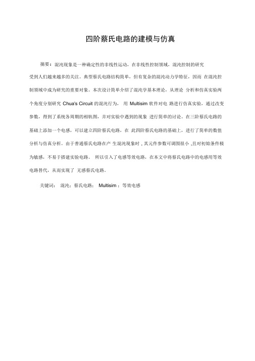
四阶蔡氏电路的建模与仿真摘要:混沌现象是一种确定性的非线性运动,在非线性控制领域,混沌控制的研究受到人们越来越多的关注。
典型蔡氏电路结构简单,但有复杂的混沌动力学特征,因而在混沌控制领域中成为研究的重要对象。
本次设计简单介绍了混沌学基本理论,从理论分析和仿真实验两个角度分别研究Chua's Circuit 的混沌行为,用Multisim 软件对电路进行仿真实验,通过改变参数,得到了系统各周期的相轨图,并对实验中遇到的现象进行简单的讨论。
在三阶蔡氏电路的基础上添加一个电感,可以建立四阶蔡氏电路,在此四阶蔡氏电路的基础上,进行了简单的数值分析与仿真分析。
由于普通蔡氏电路在产生混沌现象时, 其元件参数可调围很小,且对初始条件极为敏感,不易于搭建实验电路。
所以引入了电感等效电路,在本文中将蔡氏电路中的电感用等效电路替代,从而实现了无感蔡氏电路。
关键词:混沌;蔡氏电路;Multisim ;等效电感Experimental Study of Chua's circuit chaoticAbstract :Chaos is a deterministic non-linear movement, in the field of nonlinear control, chaotic control get more and more attention by people. Typical Chua's circuit is simple, but complex and chaotic dynamics characteristics, so become an important research object in the field of chaos control . The design simple introduced the basic theory of chaos, study the chaotic behavior of Chua'sCircuit from two angles of the theoretical analysis and experimental with Multisim circuit simulation software, by changing the parameters, get each cycle tracks phase diagram of the system, simple discuss the experimental phenomena encountered, couple the second-order Chua's circuit with a linear circuit ("oscillation absorber"), get even more chaotic behavior of the rich. As the general chaos in Chua's circuit in the production, its range of component parameters adjustable is very small, and extremely sensitive to initial conditions, hard to set up experimental circuit. Therefore introduce the inductor equivalent circuit, in this final, change the inductor of Chua's circuit with the equivalent circuit, thus achieving non- inductor of Chua's circuit.Key words :chaos; Chua's circuit; Multisim; vibration absorber; equivalent inductance目录第一章混沌学基本理论. (5)1.1 混沌的简单介绍 (5)1.1.1 混沌的定义. (5)1.1.2 混沌的主要特征. (6)1.1.3 混沌的现实意义和应用. (7)1.1.4 混沌的前景展望. (8)1.2 蔡氏电路简介 (9)1.3 蔡氏电路的研究 (10)1.4 软件介绍 (10)1.4.1 数值仿真软件. (10)1.4.2 电路仿真软件. (11)第二章三阶蔡氏电路分析. (12)2.1 电路原理与数学建模 (12)2.2 数值仿真分析 (13)2.3 蔡氏二极管等效电路设计 (15)2.4 三阶蔡氏电路制作和电路仿真 (17)2.5 蔡氏电路的平衡点及稳定性 (19)第三章四阶蔡氏电路分析. (22)3.1 四阶蔡氏电路数学建模 (22)3.2 四阶蔡氏电路数值仿真分析 (24)3.3 四阶蔡氏电路电路仿真分析. (25)3.4 三阶蔡氏电路等效电感分析 (27)第四章总结与分析. (30)参考文献. (31)致. (32)附录Matlab 程序 (33)第一章混沌学基本理论1.1 混沌的简单介绍1.1.1 混沌的定义混沌是非线性动力学系统所特有的一种运动形式,是自然界及社会中的一种普遍现象,它是一种在确定性系统中所出现的类似随机而无规则运动的动力学行为。
verilog之四位全加器的编译及仿真(用开源免费的软件——iverilog+GTKWave)
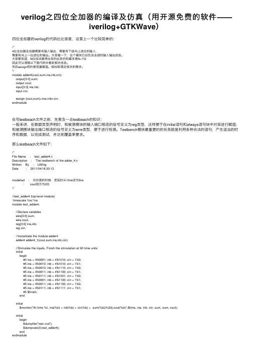
verilog之四位全加器的编译及仿真(⽤开源免费的软件——iverilog+GTKWave)四位全加器的verilog的代码⽐⽐皆是,这⾥上⼀个⽐较简单的:/*4位全加器全加器需要有输⼊输出,需要有下级向上进位的输⼊,需要有向上⼀位进位的输出。
⼤家看⼀下,这个模块已经包含全部的输⼊输出信息。
⼤家都知道,N位加法器得出来的出来的和最多是N+1位因此可以清晰从下⾯代码中看到相关信息。
然后assign⽤的是阻塞赋值。
相加即满⾜相关的需求。
*/module adder4(cout,sum,ina,inb,cin);output[3:0] sum;output cout;input[3:0] ina,inb;input cin;assign {cout,sum}=ina+inb+cin;endmodule在写testbeach⽂件之前,先普及⼀点testbeach的知识:⼀般来讲,在数据类型声明时,和被测模块的输⼊端⼝相连的信号定义为reg类型,这样便于在initial语句和always语句块中对其进⾏赋值;和被测模块输出端⼝相连的信号定义为wire类型,便于进⾏检测。
Testbench模块最重要的的任务就是利⽤各种合法的语句,产⽣适当的时序和数据,以完成测试,并达到覆盖率要求。
那么testbeach⽂件如下:/*File Name : test_adder4.vDescription : The testbench of the adder_4.vWritten By : LiMingData : 2011/04/18 20:13modefied : 在仿真的时候,把延时从10ns改为5ns: cout显⽰为2位*///test_adder4 (top-level module)`timescale 1ns/1nsmodule test_adder4;//Declare variableswire[3:0] sum;wire cout;reg[3:0] ina,inb;reg cin;//Instantiate the module adder4adder4 adder4_1(cout,sum,ina,inb,cin);//Stimulate the inputs, Finish the stimulation at 90 time unitsinitialbegin#0 ina = 4'b0001; inb = 4'b1010; cin = 1'b0;#5 ina = 4'b0010; inb = 4'b1010; cin = 1'b1;#5 ina = 4'b0010; inb = 4'b1110; cin = 1'b0;#5 ina = 4'b0011; inb = 4'b1100; cin = 1'b1;#5 ina = 4'b0111; inb = 4'b1001; cin = 1'b0;#5 ina = 4'b0001; inb = 4'b1100; cin = 1'b1;#5 ina = 4'b0011; inb = 4'b1100; cin = 1'b0;#5 ina = 4'b0111; inb = 4'b1111; cin = 1'b1;#5 $finish;endinitial$monitor("At time %t, ina(%b) + inb(%b) + cin(%b) = sum(%b)(%2d),cout(%b)",$time, ina, inb, cin, sum, sum, cout);initialbegin$dumpfile("test.vcd");$dumpvars(0,test_adder4);endendmodule由于是在windows的cmd下进⾏命令⾏的运⾏,所以有时候每次输⼊⼀个命令显得很费时间,所以我这⾥⼜写了⼀个(批处理⽂件)bat⽂件:go.batECHO OFFECHO *********************************ECHO * Batch fileECHO *********************************ECHO *ECHO ONiverilog -o test adder4.v test_adder4.vvvp -n test -lxt2cp test.vcd test.lxtgtkwave test.lxt(说明⼀下,我在windows下安装了gnuwin的软件,即能在windows下⽤gnu的⼀些⼩的实⽤的⼯具!)哈哈,这⾥就可以⼀键运⾏了,上⾯的⼀些命令的解释可以到我的“wndows下如何⽤Iverilog+GTKWave进⾏verilog的编译和查看仿真波形”的博⽂⾥去看看吧。
模电第四版习题解答

模拟电子技术基础第四版清华大学电子学教研组编童诗白华成英主编自测题与习题解答目录第1章常用半导体器件‥‥‥‥‥‥‥‥‥‥3第2章基本放大电路‥‥‥‥‥‥‥‥‥‥‥14第3章多级放大电路‥‥‥‥‥‥‥‥‥‥‥31第4章集成运算放大电路‥‥‥‥‥‥‥‥‥41第5章放大电路的频率响应‥‥‥‥‥‥‥‥50第6章放大电路中的反馈‥‥‥‥‥‥‥‥‥60第7章信号的运算和处理‥‥‥‥‥‥‥‥‥74第8章波形的发生和信号的转换‥‥‥‥‥‥90第9章功率放大电路‥‥‥‥‥‥‥‥‥‥‥114第10章直流电源‥‥‥‥‥‥‥‥‥‥‥‥‥126第1章常用半导体器件自测题一、判断下列说法是否正确,用“×”和“√”表示判断结果填入空内。
(1)在N 型半导体中如果掺入足够量的三价元素,可将其改型为P 型半导体。
( √ )(2)因为N 型半导体的多子是自由电子,所以它带负电。
( × )(3)PN 结在无光照、无外加电压时,结电流为零。
( √ )(4)处于放大状态的晶体管,集电极电流是多子漂移运动形成的。
( × )(5)结型场效应管外加的栅一源电压应使栅一源间的耗尽层承受反向电压,才能保证其R大的特点。
( √ )GSU大于零,则其输入电阻会明显变小。
(6)若耗尽型N 沟道MOS 管的GS( × )二、选择正确答案填入空内。
(l) PN 结加正向电压时,空间电荷区将 A 。
A.变窄B.基本不变C.变宽(2)稳压管的稳压区是其工作在 C 。
A.正向导通B.反向截止C.反向击穿(3)当晶体管工作在放大区时,发射结电压和集电结电压应为 B 。
A.前者反偏、后者也反偏B.前者正偏、后者反偏C.前者正偏、后者也正偏(4) U GS=0V时,能够工作在恒流区的场效应管有 A 、C 。
A.结型管B.增强型MOS 管C.耗尽型MOS 管三、写出图Tl.3所示各电路的输出电压值,设二极管导通电压U D=0.7V。
- 1、下载文档前请自行甄别文档内容的完整性,平台不提供额外的编辑、内容补充、找答案等附加服务。
- 2、"仅部分预览"的文档,不可在线预览部分如存在完整性等问题,可反馈申请退款(可完整预览的文档不适用该条件!)。
- 3、如文档侵犯您的权益,请联系客服反馈,我们会尽快为您处理(人工客服工作时间:9:00-18:30)。
Design -> Report Area
Library(s) Used: typical (File: /home/zhangchun/demo/typical.db) Number of ports: Number of nets: Number of cells: Number of references: 6 13 11 6
2014-8-20
清华大学微电子学研究所 张春
7/33
Synchronous Sequential Logic
所有的存储单元都由同一时钟边沿到来时进行时钟同步( clocked) 组合逻辑电路部分:
– 在每个时钟信号有效时,输入才改变 – 在下一次时钟信号有效之前, 所有输出必须稳定
2014-8-20 清华大学微电子学研究所 张春 8/33
Place & Route
Layout
2014-8-20
清华大学微电子学研究所 张春
3/33
什么是综合
逻辑综合 使用EDA工具将设计从RTL到逻辑门级的转换过程。
逻辑综合的目的 决定电路门级结构、寻求时序、面积、功耗的平衡。
2014-8-20
清华大学微电子学研究所 张春
4/33
综合的过程
逻辑综合及门级仿真
2014-8-20
清华大学微电子学研究所 张春
1/33
内容摘要
综合及相关基本概念
– Cell-based ASIC(标准单元) – Static timing analysis (STA,静态时序分析)
基本的综合过程 门级仿真
2014-8-20
清华大学微电子学研究所 张春
– – 在触发时钟边沿,输出并不能立即变化 与逻辑门的延迟类似,也由两部分组成: • 内在Clock-to-Q时间 • 负载相关Clock-to-Q时间
2014-8-20
清华大学微电子学研究所 张春
9/33
Critical path & Clock cycle
关键路径: 任何两个寄存器之间的最慢路径 最高时钟频率依赖于这条关键路径 具体而言, 时钟周期必须大于:
2014-8-20
392.515198 undefined
清华大学微电子学研究所 张春 23/33
检查综合结果-Area
Attributes: b - black box (unknown) h - hierarchical n - noncombinational r - removable u - contains unmapped logic
Design -> Report Cell Design -> Report Reference
Cell Reference Library Area Attributes -------------------------------------------------------------------------------U24 XOR2X1 typical 26.611200 U25 NOR2X1 typical 9.979200 U26 MXI2X1 typical 23.284800 U27 NAND2X1 typical 9.979200 U28 CLKINVX1 typical 9.979200 U29 MXI2X1 typical 23.284800 U30 CLKINVX1 typical 9.979200 q_reg[0] DFFRHQX1 typical 69.854401 n q_reg[1] DFFRHQX1 typical 69.854401 n q_reg[2] DFFRHQX1 typical 69.854401 n q_reg[3] DFFRHQX1 typical 69.854401 n -------------------------------------------------------------------------------Total 11 cells 392.515198 2014-8-20 清华大学微电子学研究所 张春 24/33
Analyze, elaborate read_verilog, read_VHDL
Analyze and resolve design problems
report_timing report_area
Define design environment
set_operating_conditions set_wire_load_model set_driving_cell, set_load
create_clock, set_clock_uncertainty set_input_delay, set_output_delay set_max_area
Specify library
target_library link_library
Compile design
compile
Read design
清华大学微电子学研究所 张春
21/33
检查电路图
Schematic View
Symbol View
2014-8-20
清华大学微电子学研究所 张春
22/33
检查综合结果-Area
**************************************** Report : area Design : counter Version: V-2004.06-SP2 Date : Thu Oct 25 11:52:46 2007 ****************************************
Save design database
write write_sdf
2014-8-20
清华大学微电子学研究所 张春
13/33
文件及目录准备
源代码
库文件
建立工作目录work,用于保存中间文件 mkdir work
编写配置文件:.synopsys_dc.setup
define_design_lib work –path “./work” set target_library { /home/ic/library/typical.db } set link_library { * /home/ic/library/typical.db } set symbol_library { /home/ic/library/umc18.sdb }
检查综合结果-Timing
Timing -> Report Timing Paths
2014-8-20
清华大学微电子学研究所 张春
25/33
输出结果(DB/VHDL/Verilog/SDF)
File -> Save 以DB格式保存综合后的结果 File -> Save As 以VHDL/Verilog形式输出电路网表
File -> Save Info -> Design Timing 输出时序反标文件
2014-8-20
清华大学微电子学研究所 张春
26/33
内容摘要
综合及相关基本概念
– Cell-based ASIC(标准单元) – Static timing analysis (STA,静态时序分析)
2/33
典型的ASIC设计流程
Funct. Spec RTL Logic Synth. Front-end Gate-level Net. Floorplanning Behav. Simul.
Stat. Wire Model
Gate-Lev. Sim. Parasitic Extrac.
Back-end
基本的综合过程 门级仿真
2014-8-20
清华大学微电子学研究所 张春
27/33
门级仿真
综合工具
RTL级设计文件 Counter.vhd 测试平台文件 tb.vhd
门级网表文件 post.v (post.vhdl)
时序反标文件 Counter-post.sdf
仿真器
功能仿真
仿真器
门级仿真
库文件 Umc18.v
Combinational area: 113.097603 Noncombinational area: 279.417603 Net Interconnect area: undefined (No wire load specified) Total cell area: Total area:
2014-8-20
清华大学微电子学ed ASIC
使用预先设计好的逻辑单元 (标准单元,standard cells)和功 能单元 (宏单元,megacells) 标准单元
– 基本门电路,Primitive Gates (and, or, inv, …) – 多路选择器,Multiplexers – 寄存器,Registers
内容摘要
综合及相关基本概念
– Cell-based ASIC(标准单元) – Static timing analysis (STA,静态时序分析)
基本的综合过程 门级仿真
2014-8-20
清华大学微电子学研究所 张春
12/33
基本综合过程
Prepare HDL Code
Set design constraints