电网事故外文翻译
电力系统外文翻译
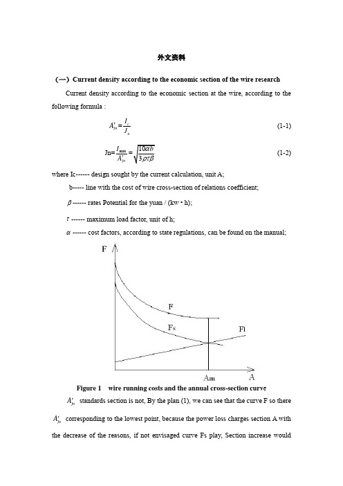
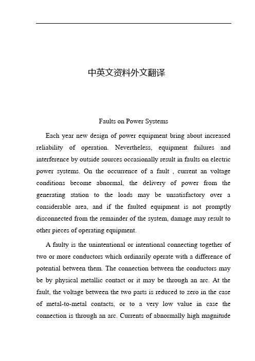
外文资料(一)Current density according to the economic section of the wire researchCurrent density according to the economic section at the wire, according to the following formula :jn A '=c nI J (1-1) Jn=max jn I A '(1-2) where Ic ------ design sought by the current calculation, unit A;b ----- line with the cost of wire cross -section of relations coefficient;β------ rates Potential for the yuan / (kw • h);τ------ maximum load factor, unit of h;α------ cost factors, according to state regulations, can be found on the manual;Figure 1 wire running costs and the annual cross-section curv ejn A ' standards section is not, By the plan (1), we can see that the curve F so there jn A ' corresponding to the lowest point, because the power loss charges section A with the decrease of the reasons, if not envisaged curve Fs play, Section increasewouldinevitably lead to the increase in operating costs. So admission standards section should not only satisfy the minimum requirements of the power loss, but also reduce running costs less because(1) In general, the establishment of factories or load a development process, the initial value is smaller than the design, gradually in order to achieve the expected value, butA'network is completed by the load considered, This is not consistentjnwith the actual situation, in other words, power loss is not designed so much to the imagination;(2) Design calculations indicate the actual load Ic than big design value;(3) F curve relatively flat bottom.Therefore, the selection criteria section, it should be by choiceA'smaller thanjnthe cross section, as F curve flat bottom, operating costs of less impact, taking into account the load values, as well as changes in the law, Theoretical calculation of the power loss will be larger than the actual value. with the options to save much of the initial investment and the consumption of non-ferrous metals.In the factory power supply system design using Jn wire cross section, Energy losses are still high volume of large factories into line and the electric network in the short occasions application. Method used Jn wire cross section still in use, but it should be noted that this method has the following problems :(1) 1.2 formula of the b value is not constant, the domestic tariff beta value is not uniform, Operating costs of Europium value in different countries should have the period of change.(2) This method is only from the operating expenses for at least the premise, not the investment, operating costs and the overall efficiency.Therefore, the proposed foreign books "at least expenditure," the wire cross section. Under Ic can elect to meet the heating requirements of the specifications 2-3 lead, their investment costs and operating costs are different. High investment costs of cross-section wire resistance by small and less power loss costs, it will be able to choose one of the best programs. But because the wire cross section Size is notcontinuous, but a broken line, in order to solve the lowest value to be used on the dogleg approximation method for the mathematical model, which is relatively more complicated, it has not been applied to engineering practice.(二)Grounding the researchCircuits are grounded in order to prevent high voltages from building up on the conductors, while equipment grounding aims at preventing enclosures from reaching voltages above ground. Grounding thus improves system protection and reliability and provides safety to people standing by.Grounding every circuit, however, makes the system susceptible to excessive currents should a short circuit develop between a live conductor and ground. Thus, not all neutrals of wye-connected loads (especially large motors) should be grounded. Grounding should then be practiced selectively, especially on the primary distribution system, as shown in Fig. -1. In part (a), disconnection of motors M1 and M3 for maintenance of repair deprives the 2400-volt system of a ground. It is preferable to ground the system at the source, that is, at the transformer neutral in Fig.-1 (b).2400V13.8kVM1M2M3M4(a)2400V13.8kVM1M2M3M4(b)Fig.2 Circuit grounding done selectively(a) at a few motor neutrals (load);(b) at the transformer neutral (source)Metal enclosures,raceways,and fixed equipments are normally grounded. However,motor and generators well insulated from ground,and metal enclosurs used to protect cables or equipments from physical damage,may be left ungrounded.Aslo,portable tools and home appliances,such as refrigerators and air conditions,need not be grounded if constructed with double insulation.Some ac circuits are required to be ungrounded as,for instance,in anesthesizing locations in hospital.In fact,line isolation monitors are installed in such cases,capable of sounding warning signals.High-voltage services (>1000V) are not necessarily grounded, but they must be so if they supply portable equipment.Metal underground water pipes are normally used for grounding, If their length is judged inadequate, they may be complemented by other means, such as a building metal frame or some underground pipe of tank.中文译文(一)按照经济电流密度选择导线截面的研究按照经济电流密度选择导线截面时,可根据下式:jn A '=c n I J (1-1) Jn=maxjn I A '(1-2)式中 Ic------设计时求得的计算电流,单位为A ;b-----线路造价与导线截面间的关系系数;β------电价,电位为元/(kw·h)τ------最大负荷损耗系数,单位为h ;α------费用系数,根据国家规定,可在有关手册中查到;图1 导线截面与年运行费的关系曲线jn A '未必是标准截面,那么,由图 1可以看出,曲线F 所以出现对应于jn A '的最低点,是因为电能损耗费随截面A 的增大而减小的缘故,设想如果没有曲线Fs 起作用,截面的增加必然引起运行费用的增加。
电力系统故障中英文对照外文翻译文献
中英文资料外文翻译Faults on Power SystemsEach year new design of power equipment bring about increased reliability of operation. Nevertheless, equipment failures and interference by outside sources occasionally result in faults on electric power systems. On the occurrence of a fault , current an voltage conditions become abnormal, the delivery of power from the generating station to the loads may be unsatisfactory over a considerable area, and if the faulted equipment is not promptly disconnected from the remainder of the system, damage may result to other pieces of operating equipment.A faulty is the unintentional or intentional connecting together of two or more conductors which ordinarily operate with a difference of potential between them. The connection between the conductors may be by physical metallic contact or it may be through an arc. At the fault, the voltage between the two parts is reduced to zero in the case of metal-to-metal contacts, or to a very low value in case the connection is through an arc. Currents of abnormally high magnitudeflow through the network to the point of fault. These short-circuit currents will usually be much greater than the designed thermal ability of the condition in the lines or machines feeding the fault . The resultant rise in temperature may cause damage by the annealing of conductors and by the charring of insulation. In the period during which the fault is permitted to exist, the voltage on the system in the near vicinity of the fault will be so low that utilization equipment will be inoperative. It is apparent that the late conditions that exist during a fault, and provide equipment properly adjusted to open the switches necessary to disconnect the faulted equipment from the remanding of the system. Ordinarily it is desirable that no other switches on the system are opened, as such behavior would result in unnecessary modification the system circuits.A distinction must be made between and an overload. An overload implies only that loads greater than the designed values have been imposed on system. Under such a circumstance the voltage at the overload point may be low, but not zero. This undervoltage condition may extend for some distance beyond the overload point into the remainder of the system. The current in the overload equipment are high and may exceed the thermal design limits. Nevertheless, such currents are substantially lower than in the case of a fault. Service frequently may be maintained, but at below-standard voltage.Overloads are rather common occurrences in homes. For example, a housewife might plug five waffle irons into the kitchen circuit during a neighborhood part. Such an overload, if permitted to continue,would cause heating of the wires from the power center and might eventually start a fire. To prevent such trouble, residential circuits are protected by fuses or circuit breakers which open quickly when currents above specified values persist. Distribution transformers are sometimes overloads as customers install more and more appliances. The continuous monitoring of distribution circuits is necessary to be certain that transformers sizes are increased as load grows.Faults of many types and causes may appear on electric power systems. Many of us in our homes have seen frayed lamp cords which permitted the two conductors of the cord to come in contact with each other. When this occurs, there is a resulting flash, and if breaker or fuse equipment functions properly, the circuit is opened.Overhead lines, for the most part, are constructed of bare conductors. There are sometimes accidentally brought together by action of wind, sleets, trees, cranes, airplanes, or damage to supporting structures. Overvoltages due to lighting or switching nay cause flashover of supporting or from conductor to conductor. Contamination on insulators sometimes results in flashover even during normal voltage conditions.The conductors of underground cables are separated from each and from ground by solid insulation, which nay be oil-impregnated paper or a plastic such polyethylene. These materials undergo some deterioration with age, particularly if overloads on the cables have resulted in their operation at elevated temperature. Any small void present in the body of the insulating material will results in ionizationof the gas contained therein, the products of which react unfavorably with the insulation. Deterioration of the insulation may result in failure of the material to retain its insulating properties, and short circuits will develop between the cable conductors. The possibility of cable failure is increased if lightening or switching produces transient voltage of abnormally high values between the conductors.Transformer failures may be the result of insulation deterioration combined with overvoltage due to lightning or switching transients. Short circuit due to insulation failure between adjacent turns of the same winding may result from suddenly applied overvoltage. Major insulation may fail, permitting arcs to be established between primary and secondary windings or between winding and grounded metal parts such as the core or tank.Generators may fail due to breakdown of the insulation between adjacent turns in the same slot, resulting in a short circuit in a single turn of the generator. Insulation breakdown may also occur between one of the winding and the grounded steel structure in which the coils are embedded. Breakdown between different windings lying in the same slot results in short-circuiting extensive section of machine.Balanced three-phase faults, like balanced three-phase loads, may be handled on a lineto-neutral basis or on an equivalent single-phase basis. Problems may be solved either in terms of volts, amperes, and ohms. The handing of faults on single-phase lines is of course identical to the method of handing three-phase faults on an equivalent single-phase basis.Faults may be classified as permanent or temporary. Permanent faults are those in which insulation failure or structure failure produces damage that makes operation of the equipment impossible and requires repairs to be made. Temporary faults are those which may be removed by deenergizing the equipment for a short period of time, short circuits on overhead lines frequently are of this nature. High winds may cause two or more conductions to swing together momentarily. During the short period of contact. An arc is formed which may continue as long as line remains energized. However, if automatic equipment can be brought into operation to service as soon as the are is extinguished. Arcs across insulators due to overvoltages from lighting or switching transients usually can be cleared by automatic circuit-breaker operation before significant structure damage occurs.Because of this characteristic of faults on lines, many companies operate following a procedure known as high-speed reclosing. On the occurrence of a fault, the line is promptly deenergized by opening the circuit breakers at each end of the line. The breakers remain open long enough for the arc to clear, and then reclose automatically. In many instances service is restored in a fraction of a second. Of course, if structure damage has occurred and the fault persists, it is necessary for the breakers to reopen and lock open.电力系统故障每年新设计的电力设备都使系统的可靠性不断提高,然而,设备的使用不当以及一些偶然遇到的外在因素均会导致系统故障的发生。
电力术语(汉英)
1.保护,保护装置―――protection保护事件protection event、SOE事件Soe Records一般事件General Event保护事件描述发生错误protection event description error保护报警protection alarm保护动作protection operated保护出口protection operated 在印度,保护动作与保护出口没有区分,是同一个事情保护复归protection reset保护类型码device type code 翻译中,装置类型码和保护类型码均如此翻译2.线路保护―――110KV及以上线路保护、220KV及以上线路保护line protection - ---110KV line protection, 220KV and above line protection3.变压器保护―――两卷变压器保护、三卷变压器保护transformer protection - two-winding transformer protection, three-winding transformer protection4.间隔―――公用间隔、主变间隔、线路间隔bay ---- public bay, main transformer bay, line bay间隔浏览bay browsing5.二次回路secondary circuit二次回路正常secondary circuit normal二次回路断开secondary circuit abnormal6.开关―――开关操作、开关检修、开关信号breaker or circuit breaker(CB)breaker –breaker operation, Breaker Maintenance, breaker status开关分breaker trip开关合breaker close开关信号变位breaker status change开关刀闸变位Break/isolator change7.刀闸isolator8.地刀earth switch就地合闸local close isolator、就地跳闸local trip isolator、远方合闸命令remote close isolator远方跳闸命令remote trip isolator、合闸成功closing success、合闸失败closing failure、跳闸成功tripping success、跳闸失败tripping failure9.CT 断线CT line-break10.PT 断线PT line-break11.母线bus12.闭锁―――闭锁功能block - blocking function闭锁退出lock disable闭锁投入lock enable13.就地―――就地状态local state14.远方―――远方状态remote state (L/R)15.正常/故障/检修normal/fault/maintenance16.压板―――strap普通压板common strap、备自投压板back-up power strap、压板退出strap disable压板投入strap enable17.比例―――比例系数ratio18.模拟量analog19.开关量digital20.遥测量―――通用遥测analog general analog虚拟遥测点virtual analog21.遥控量―――control 通用遥控general control22.遥脉量energy虚拟遥脉点virtual Energy23.遥信量―――digital signal, DS通用遥信– general DS虚拟遥信点virtual DS双位置遥信DPI double point information遥信变位DS change开关遥信复归时间Reset TIme of Changed DS (Sec.)24.电流current (I)25.电压―――voltage (V)节点1越限电压– node 1 overvoltage26.电度energy27.功率因数power factor (cos )28.无功reactive power (Q)29.有功active power (P)30.直流Direct Current (DC.)31.电笛alarm whistle32.电铃alarm bell电铃时间Alarm Bell Time(Sec.)分鸣电笛trip whistle合鸣电笛close whistle音响驱动电铃电笛sound signal drive alarm bell and alarm whistle 在印度保护本身驱动三种声音,后台只发一种声音33.开入digital input DI34.开出―――digital output DO开出传动– digital output drive开出板端子digital output board outlet35.收回―――开出板端子收回、开出超时未收回reset –digital output board outlet reset DO overtime36.调压―――voltage regulation调压成功voltage regulation success、调压失败voltage regulation failure、调压升档tap raise、调压降档tap lower、调压滑档、tap slip滑档时间、调压停止(调压停档)voltage regulation-stop position,、37.档位―――position分接头档位– tap position、中心档位central position分接头―――tap分接头调节– tap changing38.变电站―――substation变电站类型Station Type变电站信号复归substation signal reset变电站信号变位substation signal change站长station manager、值长operation in charge39.零漂―――零漂校验出错zero drift – zero drift calibration error40.控制字control word41.死区dead zone ,42.切除fault clearing43.防抖动时间Debouncing Delay防抖动时间变位次数Change Count During Debouncing Delay ,44.定值下传定值send setting group to protection定值区CRC自检出错CRC check error of setting group定值区出错setting group error定值模板setting template定值类型码setting type code45.CPU告警CPU alarm装置告警device alarm1.2.ROM区和校验出错check sum of ROM error3.配置信息校验出错configuration check error4.RAM自检出错RAM self-check error5.配置表自检出错configuration table self-check error6.PLC表自检出错PLC table self-check error7.EEPROM自检出错EEPROM self-check error8.开出检验出错digital output check error9.通信中断communication break10.串口通信中断serial communication break11.AD采样出错A/D sampling error383 组号group no 385 功能码function code386 对象号object no 384 路数route num46.五防fail-safe unit。
电力系统继电保护外文及翻译
Power System ProtectionsThe steady-state operation of a power system is frequently disturbed by various faults on electrical equipment. To maintain the proper operation of the power system, an effective, efficient and reliable protection scheme is required. Power system components are designed to operate under normal operating conditions.However, due to any reason, say a fault, there is an abnormality, it is necessary that there should be a device which senses these abnormal conditions and if so, the element or component where such an abnormality has taken place is removed, i.e. deleted from the rest of the system as soon as possible. This is necessary because the power system component can never be designed to withstand the worst possible conditions due to the fact that this will make the whole system highly uneconomical. And therefore, if such an abnormality takes place in any element or component of the power system network, it is desirable that the affected element/component is removed from the rest of the system reliably and quickly in order to restore power in the remaining system under the normal condition as soon as possible.The protection scheme includes both the protective relays and switching circuits, i.e. circuit breakers. The protective relay which functions as a brain is a very important component. The protective relay is a sensing device, which senses the fault, determines its location and then sends command to the proper circuit breaker by closing its trip coil. The circuit breaker after getting command from the protective relay disconnects only the faulted element. this is why the protective relay must be reliable, maintainable and fast in operation.In early days, there used to be electromechanical relay of induction disk-type.However, very soon the disk was replaced by inverted cup, i.e.hollow cylinder and the new relay obtained was known as an induction cup or induction cylinder relay. This relay, which is still in use, possesses several important features such as higher speed; higher torque for a given power input an more uniform torque.However, with the advent of electronic tubes, electronic relays having distinct features were developed during 1940s. With the discovery of solid state components during 1950s, static relays with numerous advantages were developed. The use of digital computers for protective relaying purposes has been engaging the attention of research and practicing engineers since layer 1960s and 1980s. Now, the microprocessor/mini computer-based relaying scheme, because of its numerous advantages such as self –checking feature and flexibility, has been widely used in power system all over the world.The overall system protection is divided into following sections: (i)Generator protection,(ii)Transformer protection,(iii)Bus protection,(iv)Feederprotection,(v)Transmission line protection.Basic Requirements to Protective RelaysAny protection scheme, which i.e. required to safeguard the power system components against abnormal conditions such as faults, consists basically of two elements(i)Protective relay and (ii) Circuit breaker .The protective relay which is primarily the brain behind the whole scheme plays a very important role. Therefore proper care should be taken in selecting an appropriate protective relay which is reliable, efficient and fast in operation. The protective relay must satisfy the following requirements:⑴ since faults on a well designed and healthy system are normally rare, therelays are called upon to operate only occasionally. This means that therelaying scheme is normally idle and must operate whenever fault occurs. Inother words, it must be reliable.⑵ Since the reliability partly depends upon the maintenance, the relay mustbe easily maintainable.⑶ The palpation of the relay can be in two ways. One is the failure to operatein case a fault occurs an second is the relay operation when there is no fault.As a matter of fact, relay must operate if there is a fault and must notoperate if there is no fault.⑷Relaying scheme must be sensitive enough to distinguish between normaland the faulty system.Protective RelaysThe function of the protective relay is to sense the fault and energize the tripcoil of the circuit breaker. The following types of the protective relays are usedfor the apparatus such as synchronous machines, bus bar, transformer and the other apparatus and transmission line protection.(1) Over current relays,(2) Under voltage relays,(3) Under frequency relays,(4) Directional relays,(5) Thermal relays,(6) Phase sequence relays such as(i)negative sequence relays and, (ii)zerosequence relays,(7) Differential relays and percentage differential relays,(8) Distance relays such as (I)plane impedance relays,(ii)angle impedance relay,i.e. Ohm or reactance relays,(iii)angle admittance relays,i.e. Mho relaysand ,(iv)offset and restricted relays,(9)Pilot relays such as (i) wire pilot relays,(ii)carrier channel pilotrelays,(iii)microwave pilot relays. There are different types of the relayingscheme based on construction. They are:(i)electromechanicaltype,(ii)thermal relays,(iii) transduction relays,(iv)rectifier bridgerelay,(v)electronic relays,(vi)digital relaying schemes.电力系统继电保护电力系统的稳态运行经常会因各种电力设备配故障原因而被扰乱。
电气外文翻译--电力系统故障
电气外文翻译--电力系统故障Faults in the Power System___ designs。
equipment failures and interference from external sources can still lead to faults in the electric power system。
When these faults occur。
the power supply from the ___ over a wide area。
If the ___ from the rest of the system。
it could cause damage to other operating equipment.A fault occurs when two or more conductors。
___ them。
___ connect。
This n can occur through physical metallic contactor an arc。
When a fault occurs。
the voltage een the two parts is ced to zero if the n is through metal-to-metal contact or to a very low value if the n is through an arc。
As a result。
abnormally high currents flow through the ork to the point of the fault。
Theseshort-circuit currents are usually much greater than the ___。
During the d in which the fault exists。
the voltage on the systemin the near vicinity of the fault will be so low that ___。
电气类外文翻译
1、外文原文(复印件)A: The Utility Interface with Power Electronic SystemIntroductionWe discussed various powerline disturbances and how power electronic converters can perform as power conditioners and uninterruptible power supplies to prevent these poweline disturbances from disrupting the operation of critical loads such as computers used for controlling important processes, medical equipment, and the like. However, all power electronic converters (including those used to protect critical loads) can add to the inherent powerline disturbances by distorting the utility waveform due to harmonic currents injected into the utility grid and by producing electromagnetic interference, To illustrate the problems due to current harmonics ih in the input current i s of a power electronic load, consider the simple block diagram of Fig. 1-6A-1. Due to the finite (non-zero) internal impedance of the utility source which is simply represented by Ls in Fig. l-6A-1, the voltage waveform at the point of common coupling to the other loads will become distorted, which may cause them to malfunction. In addition to the voltage waveform distortion, some other problems due to the harmonic currents are as follows: additional heating and possibly overvoltages (due to resonance conditions) in the utility's distribution and transmission equipment, errors in metering and malfunction of utility relays, interference with communication and control signals, and so on. In addition to these problems, phase-controlled converters cause notches in the utility voltage waveform and many draw power at a very low displacement power factor which results in a very poor power factor of operation.The foregoing discussion shows that the proliferation of power electronic systems and loads has the potential for significant negative impact on the utilities themselves, as well as on their customers. One approach to minimize this impact is to filter the harmonic currents and the electromagnetic interference (EMI) produced by the power electronic loads. A better alternative, in spite of a small increase in the initial cost, may be to design the power electronic equipment such that the harmoniccurrents and the EMI are prevented or minimized from being generated in the first place. Both, the concerns about the utility interface and the design of power electronic equipment to minimize these concerns are discussed here.Generation of Current HarmonicsIn most power electronic equipment, such as switch-mode dc power supplies, uninterruptible power supplies (UPS), and ac and dc motor drives, ac-to-dc converters are used as the interface with the utility voltage source. Commonly, a line-frequency diode rectifier bridge as shown in Fig.1-6A-2 is used to convert line frequency ac into dc. The rectifier output is a dc voltage whose average magnitude Ud is uncontrolled.A large filter capacitor is used at the rectifier output to reduce the ripple in the dc voltage Ud. The dc voltage Ud and the dc current Id are unipolar and unidirectional, respectively. Therefore, the power flow is always from the utility ac input to the dc side. These line-frequency rectifiers with a falter capacitor at the dc side were discussed in detail in other section.A class of power electronic systems utilizes line-frequency thyristor-controlled ac-to-dc converters as the utility interface. In these converters, which were discussed in detail, the average dc output voltage Ud is controllable in magnitude and polarity, but the dc current Id remains unidirectional. Because of the reversible polarity of the dc voltage, the power flow through these converters is reversible. As was pointed out, the trend is to use these converters only at very high power levels, such as in high-voltage dc transmission systems. Because of the very high power levels, the techniques to ffdter the current harmonics and to improve the power factor of operation are quite different in these converters, as discussed in other section, than those for the line-frequency diode rectifiers.The diode rectifiers are used to interface with both the single-phase and the three-phase utility voltages. Typical ac current waveforms with minimal filtering were shown in other section. Typical harmonics in a single-phase input current waveform are listed in Table 1-6A-1, where the harmonic currents Ih are expressed as a ratio of the fundamental current Il. As is shown by Table 1-6A-l, such current waveformsconsist of large harmonic magnitudes. Therefore, for a finite internal per-phase source impedance Ls, the voltage distortion at the point of common coupling in Fig. 1-6A-1 can be substantial. The higher the internal source inductance Ls, the greater would be the voltage distortion.Current Harmonics and Power FactorAs we discussed in other section, the power factor PF at which an equipment operates is the product of the current ratio Il / Is and the displacement power factor DPF:In Eq. (1-6A-I), the displacement power factor equals the cosine of the angle Φ1. The current ratio Il / Is in Eq. (1-6A-l) is the ratio of the rms value of the fundamental frequency current component to the rms value of the total current. The power factor indicates how effectively the equipment draws power from the utility; at a low power factor of operation for a given voltage and power level, the current drawn by the equipment will be large, thus requiting increased volt-ampere ratings of the utility equipment such as transformers, transmission lines, and generators. The importance of the high power factor has been recognized by residential and office equipment manufacturers for their own benefit to maximize the power available from a wall outlet. For example from a 120V, 15A electrical circuit in a building, the maximum power available is 1.8 kW, provided the power factor is unity. The maximum power that can be drawn without exceeding the 15A limit decreases with decreasing power factor. The foregoing arguments indicate the responsibility and desirability on the part of the equipment manufacturers and users to design power electronic equipment with a high power factor of operation. This requires that the displacement power factor DPF should be high in Eq. (1-6A-I). Moreover, the current harmonics should be low to yield a high current ratio I1 / Is in Eq. (1-6A- 1).B: A Three-phase Pre-converter for Induction HeatingMOSFETBridge InvertersIntroductionHigh frequency power supplies, based on MOSFET bridge inverters, are already widely used for induction heating applications. These units require dc input voltages of about 400V to allow efficient operation of the MOSFETs employed. This supply voltage is usually obtained by using a three-phase rectifier stage, appropriate smoothing components or by employing thyristor phase- angle control to the mains supply. This kind of mains frequency power supply allows output power control of the induction heater, but it suffers from highly distorted input current waveforms with a low power factor. New legislation has been proposed to limit the maximum magnitude of harmonics drawn from the mains supply and different strategies have been suggested to reduce mains pollution.Investigations have been made to replace mains frequency power supplies by switched mode pre-converters. Switched mode converters can be designed to draw sinusoidal input currents thus avoiding the need for large and expensive mains frequency filters. At the same time these converters provide output power control and implementation of a small size high frequency isolation transformer. Power factor corrected three-phase ac-dc switched mode converter systems have usually been obtained using three identical single-phase converters with a common output filter. These systems overcome problems of mains pollution, but suffer from the disadvantage of a relatively large number of components and the need for complicated control and synchronization circuits. To reduce component costs, a structure based on a boost converter with three-phase input diode rectifier has been suggested. However, when operated direct-off-line from a three-phase 415V mains supply, this structure leads to high output voltages above lkV.In this paper, a novel method to achieve power factor correction for three-phase ac to dc power converters is described. The proposed topology is based on the buck converter and allows therefore output voltages to be below the maximum input voltage. The proposed topology utilizes a three- phase diode rectifier at the mains input and a single active switching device. The active switching device operates underzero-current switching conditions, resulting in very high converter efficiencies and low RFI emissions.Zero-current switching technique allows semiconductor devices to be operated at much higher switching frequencies and with reduced drive requirements compared with conventional switched mode operation.The proposed single-ended resonant converter with three-phase diode rectifier offers good opportunities for medium power, ac to dc applications. It combines simplicity and ease of control with high converter efficiency and high output power capabilities. It will be shown in the paper, that these characteristics make the converter very suitable as a direct replacement for the conventional mains frequency power supply used to supply induction heating MOSFET bridge inverters.General DescriptionA block diagram of the proposed induction heating system is shown in Fig. 1-6B-1. Block 1 represents the pre-converter that produces the dc supply voltage to feed to the RF MOSFET bridge inverter. Its output voltage should be controllable over a wide range to control the output power of the inverter and it must be able to operate with a wide range of load resistance to compensate load changes of the induction heating inverter stage. The pre-converter should operate direct-off-line from a three-phase 415V mains supply, drawing sinusoidal input current waveforms with a power factor approaching unity.Block 2 shows the RF MOSFET bridge inverter.The required maximum supply voltage of the MOSFET bridge lies between 300V and 400V. Block 3 represents the control and protection circuit used to stabilise the output power and to allow reliable operation of the induction heater in an industrial environment.Principle of Converter OperationA circuit diagram of the proposed three-phase ac to dc converter topology is shown in Fig. 1- 6B-2. The converter input currents are filtered through the input inductors L1, L2, L3. These inductors are designed so that the converter input currents are approximately constant over a whole switching cycle.During the OFF time of switch S, all three capacitors are charged by the inputcurrents I1, I2,I3. Consequently the three capacitor voltages Uc1, Uc1, Uc1 begin simultaneously to increase at a rate proportional to their respective input currents. If discontinuous operation is assumed the initial voltages of all capacitors C1, C2, C3 are zero when the switch ceases conducting. Hence, the peak voltage across each capacitor at the end of the OFF interval is proportional to their respective phase input current during the same OFF interval. Since capacitor voltages always begin at zero, it means that their average values during OFF time are linearly dependent on the phase input currents.During the ON time of switch S the energy stored in the three input capacitors C1, C2 and C3 is discharged through the six rectifier diodes VD1 –VD6, the switch S and the resonant inductor Lr. The rate of current decrease is dependent on the phase currents I1, I2, I3 and the switch current I0. The average value of the capacitor voltages Uc1, Uc2, Uc3 during the ON time are not linearly dependant on their phase input currents.To draw sinusoidal input currents from the mains supply the converter must draw input currents averaged over each switching cycle which are proportional to the phase voltages. Assuming steady state converter operation, the average phase input voltages over each switching cycle must be equal to the appropriate average input capacitor voltages during the switch OFF time plus the average input capacitor voltages during the switch ON time.Average input capacitor voltages during the switch OFF time have been shown to be proportional to the phase input currents, but during the switch ON time this is not true. However, if the switch ON time of the converter is mucteshorter than the switch OFF time, then the shape of the phase input currents will approach a sinusoidal waveform with unity power factor.2、外文资料翻译译文A:效用界面与电力电子系统介绍我们之前介绍了许多种电力线的干扰情况和电力系统转换器是如何在作为电力调节器和电力电子变换器时,用来防止那些电力线扰动干扰操作的临界荷载,例如电脑用于控制重要步骤,医疗设备,以及类似其他情况。
关于电力问题的英文作文
关于电力问题的英文作文Title: Powering Our Modern World: The Unseen Force。
1. Electric Symphony: The Pulse of Urban Life。
Imagine a city, its veins pulsing with invisible energy the power grid. It's not a symphony orchestra, but a symphony of transformers and cables, humming 24/7. This都市的心脏, ChatGPT, is the unseen force that drives our daily activities.2. The Electric Spark: From Coal to Renewable。
From the fiery heart of a coal plant to the sun-kissed panels of solar arrays, every watt of power starts with a spark. The shift from fossil fuels to clean energy, like the dance between fire and electricity, is a testament to our evolving commitment to sustainability.3. The Grid's Role: The Grid's Secret Life。
The power grid, like a giant spiderweb, connects every home and business,编织着无数的供需故事. It's not just about transmitting electricity, but managing the ebb and flow, ensuring a steady flow even during peak hours, like a magician keeping the lights on.4. The Future of Power: The Smart Grid。
各类事故英文描述

for reference:1. Incident: an accidental, unplanned or uncontrolled event that had or potentially could have had negative consequences. As used in this procedure, “incident”could include injury, illness, first aid, a fire or explosion, a spill or release of materials or a “near miss”.2. LTI Case: LTI is an abbreviation meaning Lost Time Injury. A nonfatal traumatic injury that causes any loss of time from work beyond the day or shift it occurred; or a nonfatal non-traumatic illness/disease that causes disability at any time.3. Explosion: a sudden and violent release of energy. This includes both physical energy and chemical energy explosions, which are defined as follows:a. Physical energy explosions are those resulting from over-pressurization and rupture of a container or other enclosure.b. Chemical energy explosions include uncontrolled chemical reactions and combustion explosions (such as deflagrations or detonations).4. Fire: a chemical reaction in which a substance combines with oxygen (typically) and heat is released. Fires can involve solids, powders and dusts, liquids, and gases. The category of fires includes pool fires, jet fires, and flash fires. For the purposes of the recording and reporting process, consider that whenever flames are present, a fire has occurred.a. Exclude as fires: Electrical equipment damaged due to equipment failure, electrical power surge, over current, etc. These are reported as other incidents and may include:1) “Hot” or smoking lighting ballasts (no flames visible)2) Electrical equipment scorching due to over current3) Activities which involve the planned use of a flame or fire (i.e. welding, heating by flame)b. Include as fires:1) Hydrogen (and other materials) fires even though hydrogen burns without a visible flame.2) Electrical equipment scorching due to flame.5. Hazardous Material: any material including waste regardless of form could cause harm to people, environment or property when the people, environment or property is exposed to the material.6. Reactive Chemical Incident: the undesirable and unplanned reaction between two or more materials that results in, or could readily result in damage to property, release of materials to the environment, or injury to personnel.a. This includes bulged or over-pressurized intermediate, product, and waste containers.b. This does not include intended chemical reactions occurring during normal and routine process or laboratory operations unless such reactions actually result in one or more of the previously mentioned conditions.7. Other Incident: an incident that does not clearly fit into any of the specified incident types. However, if the damage or loss exceeds 80,000 RMB, this incident must be reported in the Other Incident category. This may include:a. Transfer of chemicals to incorrect tank or vessel.b. Damage to company owned vehicles including fork trucks, cranes, etc.c. Damage to fixed assets such as buildings or process equipment.d. Reactive chemical property incidents.8. Process Area: a location where processing, storage, and/or handling of chemicals occurs. This includes manufacturing areas, chemical laboratories, warehouses, tank farms, transfer lines, loading and unloading operations. Office and lunchroom facilities, parking lots, and roadways are not considered to be Chemical Processing areas.9. Process Incident: an accidental, unplanned or uncontrolled event which occurs within a chemical process area and results either directly or indirectly in one or more of the following:a. Loss of or damage to propertyb. Discharge of any chemical or material to the surrounding environmentc. Disruption of normal operations10. Release: the unexpected/unintentional release of aerosol, vapor, fume or gaseous material to the environment. The release may be gradual or sudden. Emissions from permitted process vents are not considered to be releases if the amount and concentration is in the permitted level.11. Spill: the unexpected/unintentional release of liquid or solid material to the environment. Release may be gradual or sudden. Loss of primary containment is the key determination. If it is without the intention, any material that escapes from primary containment, even if it is contained within secondary containment, is considered to be a spill.12. Accident: An incident that has actually resulted in damage or harm to people, property, equipment or the environment.13. Vehicle Incident: For purposes of this standard, “vehicle”includes automobiles, trucks, tractors, Lorries, fork trucks, motorized hand trucks crane, bicycle, and boats.14. OII Case: an injury or illness that meets the definition of being a recordable injury or illness case.15. Security incident: any activities occur at Dow Corning Zhangjiagang site which either has or may have deliberately and adversely affected any asset of Dow Corning, including people, property, products, processes, information or information systems. A security incident may also include acts which occur away from Dow Corning Zhangjiagang site but affects people, property, or information. It is not necessary that a particular act be carried to fruition, only that an attempt occurs in order to be classified as a security incident.16. Near Miss: an incident that could have reasonably resulted in a reportable OII case or property incident, but it had not been for some chance circumstance or event, including deliberate action taken to avert the incident.17. Occupational Disease: workers’ disease which is caused by the factors such as exposure to dust, radioactivity material, toxic or hazardous materials in the working activity.。
- 1、下载文档前请自行甄别文档内容的完整性,平台不提供额外的编辑、内容补充、找答案等附加服务。
- 2、"仅部分预览"的文档,不可在线预览部分如存在完整性等问题,可反馈申请退款(可完整预览的文档不适用该条件!)。
- 3、如文档侵犯您的权益,请联系客服反馈,我们会尽快为您处理(人工客服工作时间:9:00-18:30)。
英文原文名Power grid intelligent prevention 中文译名电网安全智能防护英文原文版出处:Electric & energy system T-Franc ISSN 0740-624X 2007(24)译文成绩:指导教师(导师组长)签名:译文:在大型电力系统中,严重的局部故障可以导致电力系统的不稳定现象,如发电机组的不同步(失步)、电力供需不平衡、电力频率和电压等指标偏离额定范围等。
这些现象的发展可能造成事故的扩大乃至全电网的崩溃,大范围的供电中断,造成严重的经济损失。
在这种情况下,需要及时采取有效的紧急控制措施以避免电力系统的崩溃瓦解。
解列是一种有效地避免电力系统异步运行甚至崩溃的控制措施,其基本的思想是通过主动地切断一些合理选择的输电线将整个电力网分解为若干个互相之间异步的电力孤岛,使全系统工作在一个“准正常”的状态,即各孤岛内部发电机组同步运行。
电力供需平衡,满足其他必要的安全约束条件(相对于事故前正常运行的电力系统,某些约束条件和指标可相应放宽),这样,在其他紧急控制措施的配合下,各孤岛内的子电力系统仍能保持供电,从而避免电力系统崩溃而造成的巨大的经济损失。
而在系统故障排除之后,通过恢复控制手段重新同步各个电力孤岛,可以恢复电网的完整性和全系统正常运行。
因此,在某种意义上说,解列控制是在灾变事故发生的情况下保障电力系统安全运行的最后防线。
本发明针对有可能造成电网异步甚至电网崩溃的事故,针对大规模电网,首次基于有序二元决策OBDD技术提出了合理的解列策略的方法,为灾变事故下避免电力系统的崩溃提供了一种方法。
对历史上所发生的一些知名的大型电力网崩溃事故(例如1965年美国东北部电力中断、1977年纽约电力崩溃、1996年美国西部电力系统崩溃、1999年巴西电力中断事故等)的研究表明:由于未能及时并正确地选择解列策略,即选择合理的解列点,以至于整个电力系统的崩溃,造成大区域的供电中断,造成了数以几十亿美元的经济损失。
这就使得解列策略的问题成为国内外电力界一个重大的研究课题。
目前,国内外对电力系统解列及相关领域的研究,主要集中在以下几个方面:(1)通过合理的紧急控制措施以避免系统被动的瓦解,保证电网的完整性;(2)检测和预测发电机组失步及电网被动分解的发生;(3)在事先确定的有限个解列点的情况下,研究系统的自动解列判据,如研究解列开始时刻、开始频率对解列效果及电力系统安全性的影响等,以及对继电保护装置、自动解列控制装置动作性质的研究;(4)对解列(主动或被动)后电力系统各电力孤岛内子系统的动态分析及稳定化控制。
电力系统的扩张和电力调度工作越来越重要。
目前区域调度自动化拥有高水平、SCADA(监控和DataAcquisition监控和数据采集)系统可以提供电力正常和事故条件下大量的遥测信息,包括信息测量设备、开关跳闸信息和自动保护装置操作的信息等,实现了电网实时网络监控,对电网的安全与稳定起着非常重要的作用。
然而,大量的电网故障错误消息涌入智能电网系统,系统的错误信息使得操作人员确定故障和诊断更加困难。
尤其是在电网严重故障或情况复杂时,将会有大量的失败报警信息,故障信息调度中心的调度程序不知所措,不仅错过了最佳时间处理事故,还可能由于误判扩大事故,造成停电。
在这种情况下,如何才能使调度运行人员把事故及时和准确处理,需要理解实际情况迅速确定故障位置、故障的性质和严重程度,确定停电区域,科学分析故障原因和及时采取措施缩小范围,以避免发生事故扩大,减少故障损失是放在各级调度部门面前的重要问题。
目前,一般区域电网事故是通过电话、现场查看来分析报告的。
智能电网在事故发生后,变电站值班人员,可以直接确定保护动作开关跳闸情况和装置设备故障,也可以查看人工视图。
地质调查局值班服务员根据变电站或下属报告结果,结合调度SCADA系统遥测变化信息、事件信息和其他信息,处理事故。
在处理事件时,还根据事故后的电网运行方式和电网拓扑结构事件处理程序等,手动设计可行的恢复计划,并通过远程控制或电话发出通知事件处理方式和切换操作。
可见,这种人工的方法分析处理事件,在电网安全与稳定,防止大面积停电是智能系统提供的信息与手动设计的恢复计划相互作用的。
电网的不断发展,调度部门管辖的电力线路数量大,增加设备多,设备操作和环境条件更复杂,给调度部门的正确判断和处理事件带来了新的困难。
而面对用户的电能质量日益增长的需求和供应的可靠性,当事故发生时,电网运行人员不仅要正确地判断和处理事故,而且还要提高响应速度。
现有的SCADA系统可以提供停电信息,但由于各种原因,事故自动信息特别是相关事故和保护总信号的信号允许或客观存在的情况下,日常工作调度程序和监控的电站也比比以前增加了许多,依赖变电站事故报告的来确认责任,不仅降低了调度程序的效率,还使自动化在系统中没有发挥应有的作用,导致大量的事件不能发现和处理。
此外,大量的信息积聚到一个事故,决策的基础和信息需求多,但是没有有效的和合理的方法,分散在各种数据,自动化系统将难以使用。
电力智能系统如果提供错误预防和处理程序,将影响事故在短的时间内处理完成。
这时电网值班调度员主要依靠他们自己的经验来分析和判断,提供解决事故方案。
所以,当电力智能系统无法正确分析确定事故,只能依靠值班调度员的正确判断。
此外,现有的调度系统不包含事故预测和历史故障检索,不利于一个事故发生之前的情况和处理查询,是不利于学习和体验的。
这种实时高度电网输电和分销网络,在电网事故中,要求调度员快速、准确地分析和确定故障,迅速隔离故障设备,恢复安全与稳定运行。
随着网络的发展和管理设备的增加和更复杂的调度运行方式,现有电力网络系统中并没有提供处理信息、故障诊断、错误预防和恢复程序,智能电网系统不能提供正确信息使调度员在事故发生后的做出决策。
可以看出,现今为止对灾变事故下紧急控制的研究,主要集中在采取事先避免措施、预测引起解列必要性的事故、对分解后孤岛系统的稳定化措施等,而直接对解列策略的实时搜索的研究几乎是处于空白的状况。
这种现状是首先是由于,大型电网的解列策略的搜索问题是一个非常复杂的问题,我们在理论上已经证明这是一个难题,随着电网规模的增大,备选策略空间将发生指数性爆炸。
如对IEEE标准的118个节点186条线路的电力网,其备选策略数可达到2186≈9.8×1055(近似等于1048亿个策略)。
其次,合理有效的解列策略必须在很短的时间内(几秒钟甚至1秒钟之内)给出,否则将无法有效地挽救电力系统的崩溃以避免其被动瓦解的发生。
而对于如此巨大的策略空间,现今电力工程界所流行的方法都不可能实现实时的搜索,更不可能在几秒甚至1秒钟之内在线给出解列策略。
目前,由于技术水平的局限,以及通过对实际电网拓扑结构的简化处理,在实际电力系统安全性控制中,通常是离地线在电网的某些关键线路中(例如:在各地区电网的交界处)选择若干解列点,而在需要紧急解列的情况下通过简单的判断,直接切断该地方的输电线,以达到解列电网的目的。
但这种做法缺点是把十分复杂的电网解列问题在处理上过于简单化,因此有效性不能保证。
有鉴于此,尽管多年来对电力系统在灾变事故下的解列问题已经做了多方面研究,但是仍然不能避免电力系统崩溃事故的不断发生。
正是在这样的背景下,基于主动解列的理念,研究更加有效的搜索方法,直接面对大规模电力网的复杂解列问题,实时地提供合理的解列策略,为大电力系统在严重灾变事故下避免崩溃提供了一种可能的方法。
英文原文:In large power system, faults can cause severe local power system instability, such as generating sets are not synchronized (out of step), power supply and demand imbalance, power frequency and voltage deviation from the nominal range of other indicators such. The development of these phenomena may cause expansion of the accident and the whole power grid collapse, that a wide range of power interruption, causing serious economic losses. In this case, you need to take timely and effective emergency control measures to avoid the collapse of the power system collapse. Splitting is an effective way to avoid the collapse of the power system to run asynchronously even control measures, the basic idea is to take the initiative to cut through some reasonable choice of the entire power grid transmission lines into several asynchronous power between each island, so that the entire system operates in a "quasi-normal" state, i.e. synchronous generators within each island operation, the power supply and demand balance, to meet other necessary safety constraints (relative to normal operation before the accident of the power system, some of the constraints and the corresponding indicators relaxation). Thus, in line with other emergency control measures, each island within the sub-power system can maintain power, thus avoiding the collapse of the power system caused huge economic losses. After troubleshooting in the system by means of resynchronization recovery control various power island and restore the integrity of the grid and system uptime. Thus, in a sense, splitting control in the case of catastrophic accidents protect the safe operation of the power system of the last line of defense. The present invention is likely to cause the collapse of the power grid accident asynchronous even for large-scale power grid for the first time based on ordered binary decision diagram OBDD technology presents online search and reasonable new method of splitting strategies for catastrophic accidents, prevent the collapse of the power system provides a method.History that occurred on some well-known large-scale power grid collapse accident (eg 1965 U.S. Northeast power outage, 1977 New York Power Crash, 1996 U.S. Western Power system crashes, 1999 Brazilian electricity outages, etc.) studies have shown that: Since failed to timely and correctly select the splitting strategy, that a reasonable choice of splitting points, as well as lead to the collapse of the entire power system, resulting in a large area of the power supply is interrupted, resulting in hundreds of billions of dollars in economic losses. This makes real-time search strategy splitting issue has become a major domestic and international power sector research. Currently, the splitting of the power system at home and abroad and the related areas of research, mainly in the following aspects: 1. Emergency control through reasonable measures toavoid the collapse of the passive system, to ensure the integrity of the grid; 2. Detection and prediction generation unit-step and grid passive decomposition occurs; 3 in the pre-determined point in a finite number of solutions out case studies system of automatic splitting criterion, such as research splitting start time, start frequency splitting effect and power systems the impact of security, as well as protection devices, automatic splitting properties of the control device movement; 4. pair splitting (active or passive) after the electricity power system dynamic analysis subsystems within the island and stability control.With the expansion of the power system, dispatching work increasingly important. Currently regional dispatching automation possess a high level, SCADA (Supervisory Control And DataAcquisition supervisory control and data acquisition) systems can provide power under normal and accident conditions a lot of telemetry information, including information on the measurement device, switch jump together gate information and protection and automatic device operation information, etc., to achieve real-time network monitoring, security and stability of the grid plays a very important role. However, a large number of grid failure fault message also to the influx of information to identify the operating personnel and troubleshooting more difficult. In particular, a serious fault in the power grid or complex case of failure, there will be a lot of alarm information, fault information into the dispatch center, the dispatcher overwhelmed, not only missed the best time to deal with the accident, and may be due to misjudgment leaving expansion of the accident, causing blackouts. In this case, how can dispatch duty personnel and protection operation managers timely and accurate understanding of the real situation of failure to quickly determine the fault location, nature and severity of the failure to determine the blackout zone, scientific analysis of fault causes, and failure to take timely measures to narrow the scope of the right to avoid the accident and reduce failure loss, is placed in front of all levels of dispatching department major issue.At present, the regional power grid analysis of accident reports generally or by telephone, on-site viewing and SCADA data combination. That after the accident, the substation or subordinate scheduled to report on duty phone case and protective action switch tripping and tripping device to device failure condition at the artificial view. Geological Survey attendant on duty under the substation or subordinate reporting results, combined with Scheduling SCADA system telemetry change information and events information, and other available information, combined with the experience of incident handling faults conclusions drawn. When dealing with incidents, but also according to the grid operation mode after the accident and the grid topology and incident handling procedures, etc., manual design feasible recovery programs, and through remote control or telephone issued a circular manner incident handling switchingoperation. Visible, this artificial way of analyzing and dealing with incidents, and grid security and stability and to prevent large area blackout requirements are incompatible.With the continuous development of a large grid, scheduling department jurisdiction greatly increased the number of devices, equipment, operating and environmental conditions in which the more complex scheduling department to correctly judge and deal with incidents brought new difficulties; while the face of the user of power quality and supply reliability of growing demand, scheduling department when the accident occurred, not only to correctly judge and deal with the accident, but also to try to improve the response speed.Existing SCADA system can provide the plant stops operating information, but due to various reasons, the accident automated information especially related accidents and protect the total signal signal allowed the case or objective existence, and the daily work of dispatchers and monitoring The plant station also increased a lot than before, so the confirmation of the accident mainly relies substation reporting duty, so not only reduces the efficiency of the dispatcher and did not play its due role in the automation system, resulting in a number of incidents can not be a time to discover and processing. In addition, large amounts of information into an accident, but the basis for decision-making and information needs, but there is no effective and reasonable together, dispersed in a variety of accounting data, automation systems and books, give the dispatcher find difficult to use.In the reference scenario provides error prevention and treatment program auditing, incident handling is often completed in a relatively short period of time, mainly rely on their own experience dispatcher on duty to analyze and judge, no one can provide a reference solution for the correctness of security incident handling program can only rely on the audit between the dispatcher on duty.In addition, the existing scheduling system does not contain accident anticipation and historical fault retrieval, is not conducive to a convenient accident occurred on the previous situation and deal with queries, the dispatcher is not conducive to learning and experience.This real-time highly grid electricity transmission and distribution networks. In the event of an accident the grid, requiring dispatchers to quickly and accurately analyze and determine fault, quickly isolate faulty equipment, restoring security and stability operation. With the development of network and manage devices increases, more complex dispatching operation mode, from the existing system does not provide information integration, fault diagnosis, error prevention and recovery programs available, recall the accident and other areas to provide strong all dispatchers faceted decision support.It can be seen today on the catastrophic accident until the next emergency control studies,mainly in advance to avoid taking measures to anticipate the need for an accident caused by splitting, the decomposed island system stabilization measures, and direct strategy for splitting real-time search of the situation is almost a blank. This situation is primarily because of large power grid splitting strategy search problem is a very complex issue, we have proved in theory this is an NP-hard, as the grid size increases, the alternative strategy space will occur exponential explosion. Such as the IEEE standard 118 nodes 186 grid lines, and its number of alternative strategies to reach 2186 ≈9.8 ×1055 (approximately equal to 104.8 billion strategy).Second, reasonable and effective strategy must be splitting in a very short period of time (a few seconds or even 1 second) is given, otherwise it will not be able to effectively save the collapse of the power system in order to avoid the occurrence of passive collapse. For such a huge search space strategy, power engineering are now popular search methods can not achieve real-time search, let alone in a few seconds or even 1 second column gives solutions online strategy. Currently, due to technical limitations of the level, and by the actual network topology simplification process, so in a real power system security controls, usually off in some key lines in the grid (for example: in the regional power grid junction) select several splitting point, and in need of emergency cases, by splitting the simple judgment, directly off of the local transmission lines, in order to achieve the purpose of splitting the grid. This approach to dealing with very complex issues on the oversimplification, it almost does not always effective. For this reason, despite years of catastrophic accident at the power system under the splitting problem has done several studies of the multifaceted, but still can not avoid the collapse of the power system accidents continue to occur. It is in this context, the present invention is based on the idea of splitting initiative adopted a new search method to directly face the complexity of large-scale power grid splitting problem, real-time strategy series to provide a reasonable solution for the bulk power system in serious catastrophic accidents, prevent crashes provides a possible approach.。