QuickSSHd使用说明
高清解码器 快速使用手册说明书

高清解码器快速使用手册目录1前后面壳介绍 (1)2登入 (2)3查询显示器状态 (2)4设置 (3)4.1TCP/IPv4 (3)4.2端口 (4)4.3解码器配置 (4)4.4密码配置 (5)4.5平台配置 (6)4.6级联配置 (6)4.7基本配置 (7)5现场预览 (8)6关闭系统 (9)7IE远程登录配置 (9)8参数 (12)1前后面壳介绍前面壳示意图Power 电源指示灯,灯亮表示电源接入正常USB后面壳示意图2登入连接好网线,电源线,鼠标和显示器后,右键点击屏幕弹出如下登录框。
注意:必须通过4K2K HDMI接口连接才可显示操作菜单界面。
用户名:默认用户名为admin.密码:123456.输入上述默认用户名和密码,点击“登录”。
3查询显示器状态点击“显示器”菜单,可查看到显示器各输出的状态。
显示器名称:显示该显示器的名称编号。
分割模式:该显示器当前显示的分割模式。
(可显示1/4/9/16分割)大屏拼接:显示当前是否有进行屏幕拼接或合并显示。
大屏拼接位置:当前被拼接的显示器在电视墙中所处的位置。
屏幕拼接模式:显示当前显示器的拼接组成模式。
例如2*2 (表示由四个显示器屏幕拼接而成)。
屏幕拼接分屏模式:显示当前拼接屏的分屏模式。
大屏ID:被拼接的大屏ID。
开窗:是否打开画中画窗口。
窗口坐标/宽度/高度:当前显示器的坐标及窗口的宽度和高度。
4设置点击“设置”菜单,可对解码器进行网络、端口、平台等设置。
4.1TCP/IPv4选择“TCP/IPv4”,设置解码器的IP地址,子网掩码和网关。
IP地址:该IP地址必须与平台监控软件的管理服务器IP地址处于同一局域网段中。
子网掩码:默认为255.255.255.0.网关:必须与平台监控软件的管理服务器网关一致。
设置完毕后,点击“应用”保存设置。
4.2端口选择“端口”,设置解码器的HTTP 端口和数据端口。
HTTP 端口:默认为80,该端口为远程IE登录界面端口号。
明基相机使用说明书
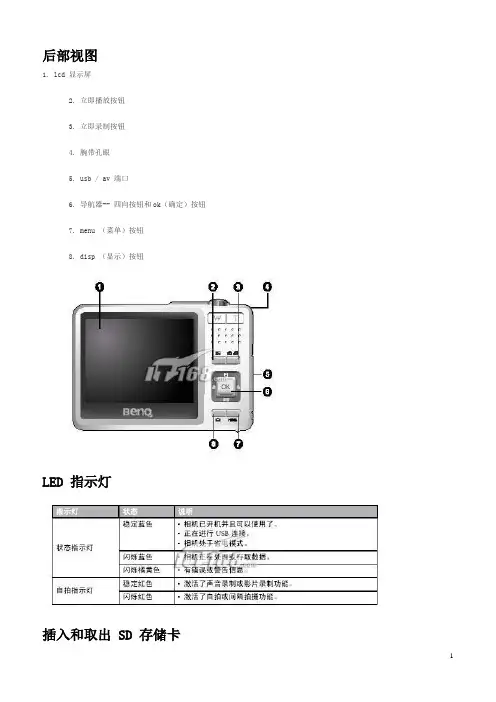
后部视图1. lcd 显示屏2. 立即播放按钮3. 立即录制按钮4. 腕带孔眼5. usb / av 端口6. 导航器-- 四向按钮和ok(确定)按钮7. menu (菜单)按钮8. disp (显示)按钮LED 指示灯插入和取出 SD 存储卡dc e600 配备24 mb 内部存储器,可让您在相机中录制视频剪辑、捕获图像或制作语音文件。
此外,还可以使用选购的sd (s ecure digital) 存储卡扩展存储容量,从而存储更多文件。
1. 在插入或取出存储卡之前,务必关闭相机的电源。
2. 按照如图所示的正确方向插入sd 存储卡。
3. 关闭电池/sd 存储卡仓盖。
如要取出sd 存储卡,请确保关闭相机电源。
轻轻地按一下存储卡的边缘,卡会弹出来。
1 在初次使用之前,务必利用本相机格式化sd 存储卡。
2 为防止意外消除sd 存储卡上的有用数据,可以将写保护开关(位于sd 存储卡侧面)推到lock (锁定)位置。
3 如需保存、编辑或消除sd 存储卡上的数据,必须解除卡锁定。
4 格式化内部存储器时,不要在相机中插入存储卡。
否则,将格式化存储卡而不格式化相机的内部存储器。
5 格式化是一个不可逆的操作,执行后无法恢复数据。
在格式化前备份您的数据。
6 存在读写问题的sd 存储卡可能无法正确格式化。
7 支持下列容量的sd 存储卡:8 mb、16 mb、32 mb、64 mb、128 mb、256 mb、512 mb 和1gb。
此相机相容由panas onic、toshiba 和sandisk 制造的sd 存储卡。
有关购买资讯,请与当地经销商联系。
设置日期和时间首次使用相机前,请先设置日期和时间。
有关的详细信息,请参见第20 页的3.4.1“设置模式菜单”中的表。
开始捕获图像2. 在拍照模式下,在lcd 显示屏中选景。
3. 先将快门按钮按下一半(1),然后完全按下(2)。
1、将快门按钮按下一半时,将自动对焦和调整曝光。
QuickGuide_ZH_TW说明书
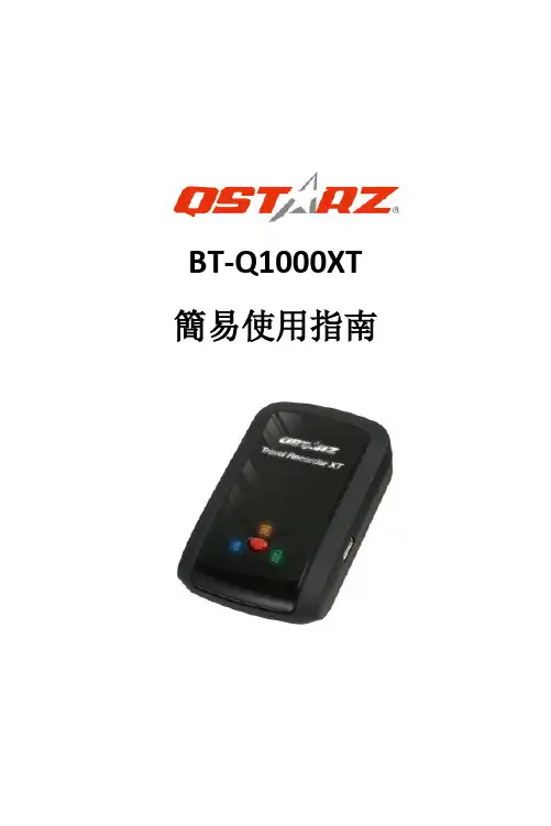
BT-Q1000XT 簡易使用指南繁體中文……………………………………………………………………………………………………………………………………………………………………………………….A. 盒裝標準配備(1) GPS 本體BT-Q1000XT (2) 可充電式鋰電池(3) 車用點煙器式充電器(4) mini USB 連接線+ 保證卡注意: 車用點煙器式充電器為BT-Q1000XT量身訂做的特別規格,所以請勿將其用來與其它設備搭配使用。
1. 2. 3.4.B. 外觀1. 電源插座(mini USB)2. 模式選擇(OFF/NAV/LOG)3. 電源狀態指示燈(紅/綠)4. 藍牙連線狀態指示燈(藍)5. GPS連線狀態指示燈(橙)6. 內建天線7. 景點座標記錄按鈕(POI)Beyond Navigation繁體中文……………………………………………………………………………………………………………………………………………………………………………………….C. 硬體功能模式選擇(OFF) 模式選擇(NAV) 模式選擇(LOG)D. 電池安裝D-1 將電池放入主體:打開主體下方的電池蓋,將電池放入主體後再把電池蓋蓋回原處固定D-2 將電池取出:打開主體下方的電池蓋,然後把電池從主體中取出繁體中文……………………………………………………………………………………………………………………………………………………………………………………….E. 為您的電池進行充電如果您是第一次使用BT-Q1000XT,請將電池完全充電。
將電源線連接電源插座並藉由mini USB線、旅行充電器或車用充電器進行充電。
充電時間約為3小時-當電源指示燈為紅色閃爍,電池將耗盡電源,請進行充電-當電源指示燈為綠色恆亮,電池正在進行充電-當電源指示燈為熄滅,電池電源已充電完畢.F. 設定BT-Q1000XTF-1 安裝USB驅動程式和QTravel PC軟體(支援Microsoft Windows XP / Vista/Win7/8/10)請至Qstarz網站/download.php或https:///Web/DownloadIndex_BTQ.php選擇GPS Travel Recorder> BT-Q1000XT,並下載最新的USB驅動程式和QTravel軟體。
全程加速器用户说明书

What's in the box Your Sprint Booster comes with the followingcomponents:Sprint Booster device * Selector SwitchInstallation instructions/Quick Start(this document) Double sided tapeTie wrap* For reference only. The actual device may vary in shape and dimensions depending on the vehicle.1User guideAUTO On the right side of the selector , there is a slide switch.Using a pointed object (pen/pin/paper clip..etc) move the switch to one of the 2 positions depending on the type of your vehicle's transmission.Move to 'M/T' position for vehicles equipped with manualtransmission or to 'A/T' position for vehicles equipped withautomatic transmission.For 'semi-automatic' transmissions (DCT, S tronic, DSG, PDK, SMG, ..etc) move to 'A/T' positionA/TM/TChoose the type of transmissionWhen the slide switch is in the 'M/T' position (manual) a reddot will appear on the LED display indicating the selection ofmanual transmission once you operate the device.Never change this selection while driving.MANUAL2Connecting the Selector SwitchAs soon as you select the type of transmission, you willneed to connect the Selector Switch to the Sprint Booster:Locate the white socket on the Sprint Booster, take the Selector switch's connector and connect it to the Sprint BoosterYou also have the option not to connect the Selector Switch.Never pull the connector from the wires.In this case the device will work in factory defaults ( 3 ). Acceleration mode/program selection , PEDAL LOCK mode &VALET mode cannot be selected without using the selector switch.34Open the vehicle's door and remove the car keys from the car. With the door open ,wait for 10 minutes before you install the device. During this time, the vehicle checks the electronic systems of the car through the CAN bus system.This step is important to allow the CANbus system to complete the diagnostictesting and avoid having the checkengine light switch On.Locate the harness connectoron the accelerator pedal.Remove the harnessconnector from the pedal.Installing Sprint Booster5Connect the Sprint Booster on the pedal. Connect the harness connector on the Sprint Booster.Make sure all connections are firmly in place(both harness connector and Sprint Booster areproperly connected).Make sure that the Sprint Booster is properly aligned with the pedal'sconnector during installation.6● The installation of Sprint Booster requiresspecial knowledge. We strongly recommend toconsult a technician for proper and safeinstallation.● Make sure you have read the operationmanual carefully before operating the device.In some vehicles it is required to remove theaccelerator pedal in order to access the harnessconnector and install Sprint Booster.The above are general instructions applying to most vehicles . In some vehicles the installation may vary .Please contact our authorized dealer network for further information.End of InstallationAfter you install the device on the pedal, you can attach the selector switch anywhere on the dashboard using the double sided tape (included).Before attaching the selector switch , clean the selected area of your dashboard with a dry cloth.Always make sure that the wire does not interfere with your foot or the accelerator pedal. Use the enclosed tie wrap to wrap the spare wire.7Acceleration modes Off (No light) SPORT (Green light) RACE (Red light) 3 Acceleration modes/presets (2 + OFF):Off (no light) – Stock response SPORT ( Green light) – improved response up to 30%RACE (Red light) - improved response up to 60%●● ●8Switching between the Acceleration modes SportPress the Main buttonto cycle through themodesRaceOffThe navigation through different modes should be done when the accelerator pedal is not pressed. Never change modes while pressing the accelerator pedal.9Acceleration ProgramsEach mode (SPORT – RACE ) comes with 9 steps-programs:Select program using the arrow buttons:1-9 in SPORT mode (Green light)and1-9 in RACE mode (Red light)Left arrow buttonSelect to decrease(9->1)Right arrow button Select to increase (1->9)The programs are only available in the SPORT and RACE mode.The selected programis shown on the LEDDisplay 1011Switch Off LED displayKeep the main button pressed for 3'' to switch Off the leddisplay (optional ).2 ''3 ''1 ''Keep button pressed for 3seconds to turn Off LEDdisplayRepeat the same procedure toturn the LED Display On.When you turn Off the LED display , the arrow buttons aredeactivated and the programs (1-9) cannot be changed. Theprograms you had selected are stored in the memory.After you switch Off the LED display you will only have theLED light On (SPORT & RACE) that indicates the mode youare in.This document contains basic information in order to install and start using the product in Acceleration mode. Make sure you have read the user guide before operating the device. The Valet Mode and Pedal lock mode are explained in detail in user guide. All titles, ownership rights and intellectual property rights in and relating to this brochure or any copies thereof, including but not limited to copyright, logos, names, trademarks, patents, design,text, images, links, concepts and themes are owned by BOULEKOS SA or used under authorized license by BOULEKOS SA. Any reproduction, transmission, publication, performance, broadcast, alteration, license, hyperlink, creation of derivative works or other use in whole or in part in any manner without the prior written consent of BOULEKOS SA is strictly prohibited. Sprint Booster is patent protected (US 8,706,373,EP1957310,AU2006323461,CN101341042B,GR1005429,KR10 1372166,ZA200804576,MX2008007365, RU2427481). For a full list of granted patents please visit our website:.BOULEKOS SA reserves the right, but has no obligation, to change the Contents at any time. BOULEKOS SA accepts no responsibility, in any manner whatsoever, for damage and/or trouble to your vehicle or product, nor for any accidents that result from misuse of the product. Whilst every effort has been made to ensure the accuracy of the information presented, BOULEKOS SA cannot accept responsibility for errors. ‘Sprint Booster’ is a trademark of BOULEKOS SA registered in Europe (CTM), USA (®) and other countries.。
PR-0602 精确6x2 4K60 HDMI切换器快速启动指南说明书
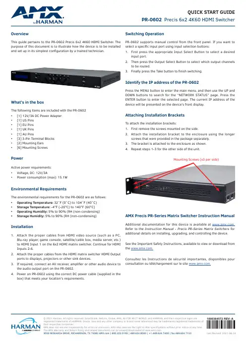
© 2021 Harman. All rights reserved. SmartScale, NetLinx, Enova, AMX, AV FOR AN IT WORLD, and HARMAN, and their respective logos are registered trademarks of HARMAN. Oracle, Java and any other company or brand name referenced may be trademarks/registered trademarks of their respective companies.AMX does not assume responsibility for errors or omissions. AMX also reserves the right to alter specifications without prior notice at any time. The AMX Warranty and Return Policy and related documents can be viewed/downloaded at .3000 RESEARCH DRIVE, RICHARDSON, TX 75082 | 800.222.0193 | 469.624.8000 | +1.469.624.7400 | fax 469.624.71531000364572 REV: A Last Revised: 2021-06-24QUICK START GUIDE PR-0602 Precis 6x2 4K60 HDMI SwitcherOverviewThis guide pertains to the PR-0602 Precis 6x2 4K60 HDMI Switcher. The purpose of this document is to illustrate how the device is to be installedand set up in its simplest configuration by a trained technician.What’s in the boxThe following items are included with the PR-0602• [1] 12V/3A DC Power Adapter• [1] US Pins• [1] EU Pins• [1] UK Pins• [1] AU Pins• [3] 3-Pin Terminal Blocks• [2] Mounting Ears• [6] Mounting ScrewsPowerActive power requirements:• Voltage, DC: 12V/3A• Power consumption (max): 15.1WEnvironmental RequirementsThe environmental requirements for the PR-0602 are as follows:• Operating Temperature: 32˚F (0˚C) to 104˚F (40˚C)• Storage Temperature: -4°F (-20°C) to 140°F (60°C)• Operating Humidity: 5% to 90% (RH (non-condensing)• Storage Humidity: 5% to 90% (RH (non-condensing) Installation1. Attach the proper cables from HDMI video source (such as a PC,Blu-ray player, game console, satellite/cable box, media server, etc.) to HDMI Input 1 on the 6x2 HDMI matrix switcher. Continue for HDMI Inputs 2-6.2. Attach the proper cables from the HDMI matrix switcher HDMI Outputports to displays, projectors or other sink devices.3. If required, connect an AV receiver, amplifier or other audio device tothe audio output port on the PR-0602.4. Power on PR-0602 using the correct DC power cable (supplied in thebox) that meets your location’s requirements.Switching OperationPR-0602 supports manual control from the front panel. If you want to select a specific input port using input selection buttons:1. First press the appropriate Input Select Button to select a desiredinput port.2. Then press the Output Select Button to select which output channelsto be routed.3. Finally press the Take button to finish switching.Identify the IP address of the PR-0602Press the MENU button to enter the main menu, and then use the UP and DOWN buttons to search for the “NETWORK STATUS” page. Press the ENTER button to enter the selected page. The current IP address of the device will be presented on the device’s front display.Attaching Installation BracketsTo attach the installation brackets:1. First remove the screws mounted on the side.2. Attach the installation bracket to the enclosure using the longerscrews that were provided in the package separately.3. The bracket is attached to the enclosure as shown.4.Repeat steps 1-3 for the other side of the unit.Mounting Screws (x3 per side)AMX Precis PR-Series Matrix Switcher Instruction Manual Additional documentation for this device is available at . Refer to the Instruction Manual - Precis PR-Series Matrix Switchers for additional details on installing, upgrading, and controlling the device.See the Important Safety Instructions, available to view or download from the .Consultez les Instructions de sécurité importantes, disponibles pour consultation ou téléchargement sur le site .。
深圳市善超科技有限公司高清网络摄像机软件说明书中文_.

目录一、软件简介二、系统配置、安装与卸载1.系统配置要求2.安装软件3.卸载软件三、登录与退出1.登录系统2.退出系统四、软件主界面介绍1. 图像浏览区2. 视频截图区3. 控制区4. 功能按钮栏五、高清网络摄像机的连接和设置1. 网络摄象机的连接2.搜索和修改网络摄象机的IP地址和端口信息六、基本功能(一系统功能1.图像显示(1图像预览(2视频截图(3视频效果调节(4调整视频有效分辨率(5降噪2.录像(1手动录像(2触发报警录像3.回放(1文件回放(2时间回放4.工作计划5.云台控制6.用户管理7.日志管理8.视频效果调整方案设置(二系统设置1.本地存储设置2.系统自动重启设置3.登录设置4.设置导入和导出5.恢复出厂设置七.网络功能(一监控主机端设置(二客户端设置1.客户端软件2. Web浏览器八.智能功能(一普通智能分析功能1.人脸检测2.遗失物体检测3.可疑物体检测4.运动检测5.隐私遮罩(二图像增强模块(可选1.除雾2.软件宽动态(三运动物体追踪模块(可选1.绊线检测和计数2.逆行检测九.报警功能1. 触发报警设置(1 添加报警触发器(2 选择报警触发事件(3 选择触发报警动作(警铃,运行程序,抓图,弹出地图,发送短信,发送电邮,转到云台预置位,报警区域放大,录像 2. 停止报警★强力播放器使用说明一、软件简介JSurveillance软件是一款智能分析实时视频监控软件,可以满足多路视频的智能分析和监控需求。
JSurveillance软件可以同时支持百万高清摄像机和视频采集卡。
JSurveillance软件具有数字录像、网络传输、支持网页浏览、动态检测、云台控制、报警输入输出、文件备份、文件回放和系统管理等基本监控功能和软件宽动态、除雾、人脸检测、可疑物体检测、遗失物体检测、物体计数、绊线检测、逆行检测等图像增强和智能分析功能。
二、系统配置、安装与卸载1.系统推荐配置要求(1硬件要求:①对于普通监控(分辨率不高于CIF4路 8路 9-16路CPU赛扬双核E3300以上双核E6600以上 Intel i5以上内存1G以上 2G以上 2G以上显卡支持各种显卡,128M显存以上硬盘硬盘容量大于200G,录像每小时每路大概1G。
多传感器导弹相机快速启动指南说明书
Multi-Sensor Bullet CameraQuick Start Guide©2020Hangzhou Hikvision Digital Technology Co.,Ltd.All rights reserved.About this ManualThe Manual includes instructions for using and managing the Product.Pictures,charts,images and all other information hereinafter are for description and explanation only.The information contained in the Manual is subject to change,without notice,due to firmware updates or other reasons.Please find the latest version of this Manual at the Hikvision website(). Please use this Manual with the guidance and assistance of professionals trained in supporting the Product.Trademarks Acknowledgmentand other Hikvision’s trademarks and logos are the properties of Hikvision in various jurisdictions.Other trademarks and logos mentioned are the properties of their respective owners.LEGAL DISCLAIMERTO THE MAXIMUM EXTENT PERMITTED BY APPLICABLE LAW, THIS MANUAL AND THE PRODUCT DESCRIBED,WITH ITS HARDWARE,SOFTWARE AND FIRMWARE,ARE PROVIDED “AS IS”AND“WITH ALL FAULTS AND ERRORS”.HIKVISION MAKES NO WARRANTIES,EXPRESS OR IMPLIED,INCLUDING WITHOUT LIMITATION,MERCHANTABILITY,SATISFACTORY QUALITY,OR FITNESS FOR A PARTICULAR PURPOSE.THE USE OF THE PRODUCT BY YOU IS AT YOUR OWN RISK.IN NO EVENT WILL HIKVISION BE LIABLE TO YOU FOR ANY SPECIAL,CONSEQUENTIAL,INCIDENTAL,OR INDIRECT DAMAGES,INCLUDING,AMONG OTHERS,DAMAGES FOR LOSS OF BUSINESS PROFITS,BUSINESS INTERRUPTION, OR LOSS OF DATA,CORRUPTION OF SYSTEMS,OR LOSS OF DOCUMENTATION,WHETHER BASED ON BREACH OF CONTRACT,TORT(INCLUDING NEGLIGENCE),PRODUCT LIABILITY,OR OTHERWISE,IN CONNECTION WITH THE USE OF THE PRODUCT,EVEN IF HIKVISION HAS BEEN ADVISED OF THE POSSIBILITY OF SUCH DAMAGES OR LOSS.YOU ACKNOWLEDGE THAT THE NATURE OF INTERNET PRO-VIDES FOR INHERENT SECURITY RISKS,AND HIKVISIONSHALL NOT TAKE ANY RESPONSIBILITIES FOR ABNORMAL OPERATION,PRIVACY LEAKAGE OR OTHER DAMAGES RE-SULTING FROM CYBER-ATTACK,HACKER ATTACK,VIRUS IN-FECTION,OR OTHER INTERNET SECURITY RISKS;HOWEVER, HIKVISION WILL PROVIDE TIMELY TECHNICAL SUPPORT IF REQUIRED.YOU AGREE TO USE THIS PRODUCT IN COMPLIANCE WITH ALL APPLICABLE LAWS,AND YOU ARE SOLELY RESPONSIBLE FOR ENSURING THAT YOUR USE CONFORMS TO THE APPLICABLE LAW.ESPECIALLY,YOU ARE RESPONSIBLE, FOR USING THIS PRODUCT IN A MANNER THAT DOES NOT INFRINGE ON THE RIGHTS OF THIRD PARTIES,INCLUDING WITHOUT LIMITATION,RIGHTS OF PUBLICITY,INTELLECTUAL PROPERTY RIGHTS,OR DATA PROTECTION AND OTHER PRIVACY RIGHTS.YOU SHALL NOT USE THIS PRODUCT FOR ANY PROHIBITED END-USES,INCLUDING THE DEVELOPMENT OR PRODUCTION OF WEAPONS OF MASS DESTRUCTION, THE DEVELOPMENT OR PRODUCTION OF CHEMICAL OR BIOLOGICAL WEAPONS,ANY ACTIVITIES IN THE CONTEXT RELATED TO ANY NUCLEAR EXPLOSIVE OR UNSAFE NUCLEAR FUEL-CYCLE,OR IN SUPPORT OF HUMAN RIGHTS ABUSES.IN THE EVENT OF ANY CONFLICTS BETWEEN THIS MANUAL AND THE APPLICABLE LAW,THE LATER PREVAILS.Regulatory InformationFCC InformationPlease take attention that changes or modification not expressly ap-proved by the party responsible for compliance could void the user’s authority to operate the equipment.FCC compliance:This equipment has been tested and found to com-ply with the limits for a Class A digital device,pursuant to part15of the FCC Rules.These limits are designed to provide reasonable protection against harmful interference when the equipment is operated in a com-mercial environment.This equipment generates,uses,and can radiate radio frequency energy and,if not installed and used in accordance with the instruction manual,may cause harmful interference to radio communications.Operation of this equipment in a residential area is likely to cause harmful interference in which case the user will be re-quired to correct the interference at his own expense.FCC conditionsThis device complies with part15of the FCC Rules.Operation is sub-ject to the following two conditions:1.This device may not cause harmful interference.2.This device must accept any interference received,including interference that may cause undesired operation.EU Conformity StatementThis product and-if applicable-the supplied accessoriestoo are marked with"CE"and comply therefore withtheapplicable harmonized European standards listed underthe the EMC Directive2014/30/EU,the RoHS Directive2011/65/EU.2012/19/EU(WEEE directive):Products marked withthis symbol cannot be disposed of as unsorted municipalwaste in the European Union.For proper recycling,returnthis product to your local supplier upon the purchase ofequivalent new equipment,or dispose of it at designatedcollection points.For more information see:www.2006/66/EC and its amendment2013/56/EU(batterydirective):This product contains a battery that cannot bedisposed of as unsorted municipal waste in the EuropeanUnion.See the product documentation for specific batteryinformation.The battery is marked with this symbol,whichmay include lettering to indicate cadmium(Cd),lead(Pb),or mercury(Hg).For proper recycling,return the battery toyour supplier or to a designated collection point.For moreinformation see:.Industry Canada ICES-003ComplianceThis device meets the CAN ICES-3(A)/NMB-3(A)standards require-ments.Cautions&WarningsThese instructions are intended to ensure that the user can use the product correctly to avoid danger or property loss.Laws and RegulationsThe device should be used in compliance with local laws, electrical safety regulations,and fire prevention regulations. TransportationKeep the device in original or similar packaging while transporting it.Power SupplyThe power source should meet limited power source or PS2 requirements according to IEC60950-1or IEC62368-1standard. Refer to the appropriate documentation for detailed information. DO NOT connect multiple devices to one power adapter,to avoid over-heating or fire hazards caused by overload.Make sure the plug is properly connected to the power socket. System SecurityThe installer and user are responsible for password and security configuration.BatteryThis equipment is not suitable for use in locations where children are likely to be present.CAUTION:Risk of explosion if the battery is replaced by an incorrect type.Dispose of used batteries according to the instructionsATTENTION:IL Y A RISQUE D'EXPLOSION SI LA BATTERIE E S T R E M P L A CÉE PA R U N E B AT T E R I E D E T Y P E INCORRECT.METTRE AU REBUT LES BATTERIES USAGÉES CONFORMÉMENT AUX INSTRUCTIONSImproper replacement of the battery with an incorrect type may defeat a safeguard(for example,in the case of some lithium battery types).DO NOT dispose of the battery into fire or a hot oven,or mechanically crush or cut the battery,which may result in an explosion.DO NOT leave the battery in an extremely high temperature surrounding environment,which may result in an explosion or the leakage of flammable liquid or gas.DO NOT subject the battery to extremely low air pressure,which may result in an explosion or the leakage of flammable liquid or gas.MaintenanceIf the product does not work properly,please contact your dealer or the nearest service center.We shall not assume any responsibility for problems caused by unauthorized repair or maintenance.A few device components(e.g.,electrolytic capacitor)require regular replacement.The average lifespan varies,so periodic checking is recommended.Contact your dealer for details. CleaningPlease use a soft and dry cloth when clean inside and outside surfaces of the product cover.Do not use alkaline detergents. Using EnvironmentWhen any laser equipment is in use,make sure that the device lens is not exposed to the laser beam,or it may burn out.DO NOT expose the device to high electromagnetic radiation or dusty environments.For indoor-only device,place it in a dry and well-ventilated environment.DO NOT aim the lens at the sun or any other bright light.Make sure the running environment meets the requirement of the device.The operating temperature shall be-30°C to+60°C(-22°F to140°F),and the operating humidity shall be95%or less(no condensing).Refer to the appropriate documentation for detailed information.DO NOT place the device in extremely hot,cold,dusty or damp locations,and do not expose it to high electromagnetic radiation. White Light Illuminator(If supported)Possibly hazardous optical radiation emitted from this product. DO NOT stare at operating light source.May be harmful to the eyes.Wear appropriate eye protection or DO NOT turn on the white light when you assemble,install or maintain the camera.EmergencyIf smoke,odor,or noise arises from the device,immediately turn off the power,unplug the power cable,and contact the service center.Time SynchronizationSet up device time manually for the first time access if the local time is not synchronized with that of the network.Visit the device via Web browse/client software and go to time settings interface. InstallationThe bracket may not support certain angles adjustment for the structure restrictions,and you should adjust the position of the bracket to achieve the desired viewing angle.This camera series shares a similar structure.We take one type among this series for demonstration.Make sure the device is firmly secured to any wall or ceiling mountings.Be sure that there is enough space to install the device and accessories.Make sure that the device in the package is in good condition and all the assembly parts are included.Make sure that the wall is strong enough to withstand at least4 times the weight of the device and the mount.The standard power supply is24VAC,please make sure your power supply matches with your device.Make sure that the power has been disconnected before you wire, install,or disassemble the device.Make sure that no reflective surface is too close to the device lens.The IR light from the device may reflect back into the lens causing reflection.CAUTION:Hot parts!Burned fingers when handlingthe parts.Wait one-half hour after switching offbefore handling parts.This sticker is to indicate that the marked item can be hot and should not be touched without taking care.For device with this sticker,this device is intended for installation in a restricted access location,access can only be gained by service persons or by users who have been instructed about the reasons for the restrictions applied to the location and about any precautions that shall be taken.DisposalPurchase separatelyOther situationsOther situations omitted WaterproofSkip this step if not necessary11x 1x 1x 1x 1x2x 2x 2x 1x 1xT10T20*1x M6×201/4-20UNC×12Interface IntroductionMemory Card SlotReset ButtonCVBS InterfaceAudio Out InterfaceAudio In InterfaceAudio In InterfaceNetwork InterfaceAlarm&Power&RS-485InterfacePower InterfaceActivate and Access Network CameraScan the QR code to get Activate and Access Camera. Note that mobile data charges may apply if Wi-Fi is unavailable.Reset and Restore CameraPress Reset button for about10s when the camera is powering on or rebooting to restore the default settings, including the user name,password,IP address,port No., etc.For the position of the reset button,refer to the figure in the interface introduction page.UD19169B-A。
青鹤摄像输入增强版说明090320
青鹤样板摄像输入系统操作手册(增强版)上海青鹤信息技术有限公司版权所有目 录一、系统安装 (3)1、硬件安装 (3)2、软件安装 (4)二、系统操作 (4)1、界面说明 (4)(一)、菜单栏 (5)(二)、工具条 (10)(三)、操作区 (14)标注输入 (15)三、示例操作说明 (15)添加照片或扫描图 (15)识别衣片 (16)缝份调整 (17)净样生成 (18)保存衣片 (18)保存为DXF格式 (18)四、问题解答 (19)一、系统安装1、硬件安装硬件部分:工作黑板、相机三脚架、相机部分。
黑板的最佳放置方式是挂在墙上。
板的下边缘离地面的距离大概在70公分左右。
三脚架加上相机后,镜头大致对着板的中间部位。
黑板用户可以自行定制。
除了黑色带磁性外,无特殊要求。
定制时,请考虑相机的像素清晰度。
技巧:使数码相机保持在工作状态,打开相机的“预览”功能,相机背部的液晶屏将显示拍摄区域,调整相机的高度和水平位置,使板面完整并且均匀显示在液晶显示屏幕中,且使工作台的边框大致充满整个画面,不要有其它多余的露出来。
能看到8(或13点)个红色的点。
由红点构成的矩形必须是个正矩形。
见下图工作板面预览图:根据板的大小,我们的红色标志点分为8个、13个和15个3种。
1米×0.9米以内的板,使用8点框架,能满足精度要求。
1米以上的板,如果采用13点或15点框架,则能提高大板情况下的精度。
上图为8点框架。
下图为13点框架。
2、软件安装供应商提供软件的安装光盘,请根据安装中的提示安装软件即可。
软件安装好后,将自动在桌面上建立“摄像输入”的快捷方式,进入时直接点击快捷方式,双击图标后,界面如下:输入我们提供的安装密码与序列号。
不要改变默认的安装路径。
软件安装完毕后,在您的电脑的C盘下,创建了Pcad Example目录,此目录下,收集了一些比较典型的照片,以供您使用评估软件。
二、系统操作1、界面说明打开“摄像输入”系统,界面显示如下:图1界面主要由菜单栏、工具条和图像列表、图像识别区域组成。
海康威视视频组件使用帮助
海康威视视频组件使用帮助支持设备型号:客户端SDK是嵌入式网络硬盘录像机、视频服务器、IP设备的配套产品,用于设备远程访问及远程控制软件的开发,适用于以下产品型号:DS-95xx、DS-96xxNVR; DS-90xx混合型硬盘录像机;DS-91xx、DS-81xx、DS-80xx、DS-70xx、DS-71xx、DS-7116、DS-72xx硬盘录像机;DS-60xx、DS-61xx视频服务器、编/解码器;IDS6002-HF/B双摄像机跟踪、IDS6101-HF/B智能设备(行为分析)、IDS52xx智能分析仪、IDS90XX、IDS91XX;DS630x_D多路解码器;IP摄像机(以下简称“IPC”):DS-2CD71xx、DS-2CD81xx、DS-2CD7xx、DS-2CD8xx、DS-2CD9xx;其他IP设备:包含IP模块、、IP快球等。
1.功能说明1.1.功能介绍图像预览通过摄像头获取视频信号显示在界面中。
云台控制对于云台可以进行控制操作,向上下左右四个方向转动,并可以设置预制轨迹使其自行运动。
布防/撤防对选定的设备进行布防、撤防,布防后SDK主动连接设备产生报警信息,撤防将不再连接同时也不会再产生报警信息。
参数配置包括通道配置、设备配置、报警参数配置、串口参数配置、用户配置、异常配置、交易配置以及ATM配置。
报警报警可分为“布防”和“监听”两种方式。
采用两种报警方式都可以接收到设备上传的移动侦测报警、视频信号丢失报警、遮挡报警和信号量报警等信息。
语音对讲、转发语音对讲能实现PC机与设备间音频的发送和接收。
语音转发功能实现将待编码后的发送的音频数据转发给设备。
日志显示操作的日志信息,可选择全部的信息日志或者只显示报警信息日志。
提示操作发生的时间、是否成功、具体操作以及错误信息的错误号。
具体错误号对应的错误见附录1.2.专业名词介绍SDK Software Development Kit 的缩写,即“软件开发工具包”在此组件中位海康威视提供的4.0.0版本的开发包。
Quick start 说明书
Quick start guideEL42208/EL42308/EL42408/ EL422585.8 GHz cordless telephone/ answering system with caller ID/call waitingInstallation preparationIf you subscribe to high-speed Internet service (Digital Subscriber Line - DSL) through your telephone lines, you must install a DSL filter between the telephone base and the telephone wall jack. The filter will prevent noise and caller ID problems caused by DSL interference. Please contact your DSL service provider for more information about DSL filters.Your product may be shipped with a protective sticker covering the handset or telephone base display - remove it before use.For customer service or product information, visit our website at or call 1 (800) 222-3111. In Canada, dial 1 (866) 288-4268.Avoid placing the telephone base too close to:• Communication devices such as: television sets, VCRs, or other cordless telephones.• Excessive heat sources.• Noise sources such as a window with traffic outside, motors, microwave ovens, refrigerators, or fluorescent lighting.• Excessive dust sources such as a workshop or garage.• Excessive moisture.• Extremely low temperature.• Mechanical vibration or shock such as on top of the washing machine or work bench.Telephone base and charger installationIf you subscribe to high-speed Internet service (Digital Subscriber Line - DSL) through your telephone lines, you must install a DSL filter between the telephone base and the telephone wall jack. The filter will prevent noise and caller ID problems caused by DSL interference. Please contact your DSL service provider for more information about DSL filters.Install the telephone base and charger as shown below.NOTES:. Use only the power adapter supplied with this product or equivalent. To order a replacement power adapter, visit our website at or call 1 (800) 222-3111. In Canada, dial 1 (866) 288-4268. . This power adapter is intended to be correctly oriented in a vertical or floor mount position. The prongs are not designed to hold the plug in place if it is plugged into a ceiling, under-the-table or cabinet outlet.4. Plug the other end of the telephone line cord into a telephone jack.5. Plug the large end of the poweradapter into an electrical outlet not connected to a wall switch.through slots.2. Plug one end of the telephone line cord into the telephone jack on the underside of the telephone base.1. Plug the small adapter into the power jack on the telephone base.Telephone base installationBattery installation & chargingInstall the battery as shown below. After installing the battery, you can make and receive short calls, but replace the handset in the telephone base orcharger when not in use. For optimal performance, charge the handset battery for at least 6 hours before use. When fully charged, the handset battery provides approximately five hours of talk time or six days of standby time. If the handset has not been used for a long time or if the battery inside is completely depleted, put it on the telephone base or charger for recharging.Step 1Insert the battery plug as indicated, making sure that it matches the color-coded label inside the battery compartment.Step 4Charge the handset, by placing the handset face up in the telephone base. The CHARGE light on the handset should be on as soon as the handset is properly placed on the telephone base.Step 3Slide the battery compartment cover up until it clicks.Step 2Place the battery and wires inside the compartment.CHARGE lightIMPORTANT INFORMATIONUse only the supplied rechargeable battery, replacement battery (part number 89- -00-00) or equivalent. To order a replacement battery, visit our website at or call 1 (800) 222-3111. In Canada, dial1 (866) 288-4268.Quick reference g uide - handsetREMOVE MENU / SEL TRANSFERor press and hold todelete all caller ID entries when the phone is not in use.mute the microphone. Press again to resume your conversation.change answering system options.record announcement;press again to quit.to record an outgoingannouncement.PLAY/STOPFor complete instructions, please refer to the user’s manual. If you are unable to find your manual, you may read and/or download the manual at .© 008 Advanced American Telephones. All rights reserved.AT&T and the AT&T logo are trademarks of AT&T Intellectual Property II, L.P. d/b/a。
- 1、下载文档前请自行甄别文档内容的完整性,平台不提供额外的编辑、内容补充、找答案等附加服务。
- 2、"仅部分预览"的文档,不可在线预览部分如存在完整性等问题,可反馈申请退款(可完整预览的文档不适用该条件!)。
- 3、如文档侵犯您的权益,请联系客服反馈,我们会尽快为您处理(人工客服工作时间:9:00-18:30)。
利用QuickSSHd或SSHDroid实现电脑对手机的远程控制
需要工具如下:
1)安卓手机端:QuickSSHd 或者 SSHDroid 附件有这两个的下载,内核是一样的,本文就以QuickSSHd讲解;
2)PC端:常用的SSH连接工具如pietty、secureCRT,SFTP工具如Winscp、SecureFX工具,本文就以pietty和winscp讲解。
----------------------------------------------------------
首先,要安装附件提供的quicksshd.2.0.3.apk,安装后启动界面如图1,当开启Wifi的时候,在Password输入相应的密码后,点右上角的开启后,已经将SShd服务运行起来了;
其次就可以在PC客户端运行pietty进行终端控制手机了。
配置和效果图如下:
输入用户root和密码后就可以登录了,登录后可以执行常用的Linux命令管理手机文件。
接着用Winscp工具登录管理文件(其实主要是管理root后的系统文件):
配置后登录,最终管理如图,左边是系统文件,右边是手机文件。
这个工具主要是对root后的手机系统文件进行操作,毕竟在手机上用Root管理器进行管理文件还是不太方便,能够在电脑上操作是最舒服的,本文就为了实现这个目标而出现的。