MBSDLecture 202-Motor Model, Display Subsystem
贝尔DSLAM维护命令手册

目录Contents一、编写概述 (3)二、适用范围 (3)三、常用操作及命令 (3)(一)配置操作 (3)1.配置IP地址 (3)2.配置模板 (3)3.配置用户板 (4)4.配置上联口 (5)5.配置VLAN (6)6.配置SNMP (6)7.配置XDSL端口 (7)8.配置ATM PVC (7)9.配置bridge port (7)(二)查看操作 (7)1.查看软件版本 (7)2 .查看上联端口 (8)3.查看板卡 (9)4.查看用户端口 (10)5.查看MAC地址 (11)6.查看用户Bridge端口信息 (12)(三)常用操作命令 (12)1.打开/关闭端口 (12)2.修改端口速率模板 (13)(四)其他操作 (13)1.登陆用户名和口令 (13)2.系统时钟 (14)3.命令提示符 (14)4.ACL访问控制 (14)5.数据备份和恢复 (15)6.告警查询 (15)7.系统重启 (15)四、常见故障及维护建议 (16)(一)常见故障 (16)1.无法同步 (16)2.频繁掉线 (16)3.同步无法拨号 (18)4.自动工单系统操作失败 (18)5.用户上网慢 (19)(二)维护建议 (20)1.检查节点备份文件 (20)2.检查节点板卡温度 (20)附录Trace&Debug命令介绍 (20)一、编写概述为帮助更好维护7302ISAM设备,编写本文档。
本文档所有命令以R2.4为基础,可能因为版本不同而有所变化,具体请参各个版本的命令手册。
二、适用范围本手册适用于所有现场工程师、局方维护人员。
三、常用操作及命令(一)配置操作1.配置IP地址从R2.4开始,7302支持单IP管理地址。
configure system single-public-ipconfigure system management host-ip-address manual:192.168.1.100/24查看配置info configure system management2.配置模板线速模板configure xdsl service-profile 1 name 2M-640K-Fastconfigure xdsl service-profile 1 min-bitrate-up 64 min-bitrate-down 64 plan-bitrate-up 640 plan-bitrate-down 2048 max-bitrate-up 640 max-bitrate-down 2048 max-delay-up 1max-delay-down 1 active其中max-delay-up、max-delay-down定义交织延时,=1表示Fast模式查看配置info configure xdsl service-profile 1协议模板configure xdsl spectrum-profile 1 name adsl2plus g992-5-aconfigure xdsl spectrum-profile 1 active其中7302默认配置如下协议,见表3-2-1:g992-5-a为ADSL2+ over POTS协议,需要单独添加,也可以按需添加其他协议,如AnnexM协议等,具体参照标准协议手册。
SIM800_硬件设计手册_V1.05

SIM800_硬件设计手册_V1.05
2
2015-02-27
目录
Smart Machine Smart Decision
1. 绪论............................................................................................................................................................... 10
Bulletin 140MT Enclosed Motor Protection Circuit B

Technical DataOriginal InstructionsBulletin 140MT Enclosed Motor Protection Circuit Breakers Bulletin Number 140MTTopic PageProduct Overview2Features2Standards Compliance and Certifications2Catalog Number Explanation3Product Selection3Accessories4Specifications6Approximate Dimensions7Additional Resources9Bulletin 140MT Enclosed Motor Protection Circuit Breakers Product OverviewBulletin 140MT enclosed Motor Protection Circuit Breakers (MPCBs) consist of a Bulletin140MT MPCB in a metallic Type 1/3/3R/4/12 enclosure.Bulletin 140MT MPCBs or Motor Protective Switching Devices (MPSDs) are UL Listed asManual, Self-Protected Combination Motor Controllers (Type E) and Manual MotorControllers (with approvals for Suitable as Motor Disconnect and Suitable for use inGroup Installation).When they are cULus Listed as Manual, Self-Protected Combination Motor Controllers,the 140MT MPCBs provide all of the necessary NEC/CEC requirements for the protectionand control of individual motor branch circuits without additional branch circuitprotective devices.According to UL 60947-4-1, CSA C22.2 No.60947-4-1, these devices may provide thefollowing control and protection functions.•Disconnect for motor branch circuit•Short-circuit protection (magnetic protection)•Overload protection (thermal protection)•Manual switching (motor control means)Features• Current range 0.1…25 A• cULus Listed for control and protection of motor loads-Motor disconnect-Short-circuit and overload protection-Motor switching (magnetic)Standards Compliance and Certifications•Enclosure types 1/3/3R/4/12•cULus Listed:-UL60947-4-1-CSA C22.2,No.60947-4-1Bulletin 140MT Enclosed Motor Protection Circuit Breakers Catalog Number ExplanationCatalog Number ExplanationProduct Selection140MT-F -CA16X a baBBulletin NumberCurrent Range [A]Code DescriptionCode Description 140MT-FMetal enclosed C/D framesCA16X 0.10…0.16CB16X 1.0…1.6DB25X 1.6…2.5DB40X 2.5…4.0DB63X 4.0…6.3DC10X 6.3…10DC16X 10…16DC20X 14.5…20DC25X18 (25)Table 1 - Motor Protective Switching DevicesRated Operational Current (I e ) [A]Motor Current Adjustment Range [A]Nominal Magnetic Trip Current [A]Max Short-circuit Current [kA]Max. 3-phase Hp Ratings (1)(1)Horsepower/kW ratings shown are for reference. The final selection of the MPCB/MPSD depends on the actual motor full load current.Max. kW, 3-Phase — AC-3(1)Cat. No.EnclosureSize480Y/277V 600Y/347V 200V 230V 480V 600V 230V 400/415V 500V 690V3PH 1PH 25 A Frame Size0.160.10…0.16 2.2 3.46550—————0.020.060.06140MT-F-CA16X A 10.63…1.014216550——0.50.750.180.250.370.55140MT-F-CB10X A 1.6 1.0…1.622346550——110.250.550.75 1.1140MT-F-CB16X A 2.5 1.6…2.5355365300.50.75 1.520.370.75 1.1 1.8140MT-F-DB25X A 4 2.5…4.05684653011330.75 1.5 2.23140MT-F-DB40X A 6.3 4.0…6.3881326530 1.5255 1.5 2.234140MT-F-DB63X A 10 6.3…101402106530337.510 2.24 6.37.5140MT-F-DC10X A 1610…16224336653035101547.51013140MT-F-DC16X A 2014.5…2028042065—57.51520 5.5101117140MT-F-DC20X A 2518…2535052550—7.57.51520 5.5111522140MT-F-DC25X ABulletin 140MT Enclosed Motor Protection Circuit Breakers AccessoriesAccessoriesTable 2 - Auxiliary ContactsX = Contact Closed; O = Contact Open (2)Connection Diagram Reference:Table 3 - Shunt Trip UnitsConnection Diagram Reference:I >>140M/MT Operator Overload (thermal) Trip Short-circuit (magnetic) TripI >>140M/MT Operator Overload (thermal) Trip Short-circuit (magnetic) TripBulletin 140MT Enclosed Motor Protection Circuit Breakers AccessoriesTable 4 - Trip Contacts(2)Connection Diagram Reference:Table 5 - Undervoltage Trip UnitsConnection Diagram Reference:I >>140M/MT Operator Overload (thermal) Trip Short-circuit (magnetic) TripI >>140M/MT Operator Overload (thermal) Trip Short-circuit (magnetic) TripBulletin 140MT Enclosed Motor Protection Circuit Breakers SpecificationsSpecificationsTable 6 - Motor Protection Circuit Breaker General DataAttribute140MT-C 140MT-D Standards compliance cULusUL 60947-4-1, CSA C22.2, No. 60947-4-1Rated Insulation Voltage U iUL/CSA[V]600Y/347VRated Impulse Withstand Voltage U imp Pollution degree3Main circuits U imp /Overvoltage Category 6 kV/III, 8 kV (Disconnect)Auxiliary circuits U imp /Overvoltage Category6 kV/III Rated Frequency [Hz]45-65Life Span Mechanical[operations]100,000Electrical (I e max.)[operations]100,000Switching Frequency [operations/hour]max. 25Ambient Temperature Storage [ °C ( °F)]-40…+85 (-40…+185)Operation [ °C ( °F)]-25…+40 (-13…+104)Climatic resistance Operating Humidity/Moisture heat (60068-2-3)5…95% Non-condensing Site Altitude [m]to 2000 N.N. (6561 ft)Protection ClassIP2X from all directionsResistance to Shock, Transport (60068-2-27)ON 15 G/11 ms OFF 30 G/11 ms Resistance to Vibration, Operation (60068-2-6) 5 G Rated Thermal Current I th up to 40 °C (104 °F) ambient temperature [A]0.1…320.63…40Rated Supply Current I e [A]0.1 (25)0.63 (40)Dependence on Temperature 40 °C (104 °F)[A]no reduction Phase-loss Protection Differential release Trip class10 fixed setting Magnetic Release Fixed setting Release current (±20%)[A]14 x I e max.(1)(1)I e max. = maximum values of setting ranges; see ratings.Total Power loss P vCircuit Breaker at rated load/operating temp.[W]4 (11)4…14Main Disconnect Switch ApplicationYes, with accessoriesBulletin 140MT Enclosed Motor Protection Circuit Breakers Approximate DimensionsApproximate DimensionsDimensions are in millimeters (inches) and are not intended to be used for manufacturing purposes.Enclosure Style ATable 7 - MPCB Connecting CharacteristicsTable 8 - Enclosure SpecificationsDescription140MT-F Construction Material MetalStructure Finish Painted textured light gray Ingress Rating IP66 (Type 1/3/3R/4/12)HandleIP66 Protection Type 1/4/4X/12, Interlock override capabilityHandle LockingFor 3 padlocks 4…8 mm (5/16 in.) in diameterAmbient Temperature0…+40 °C (32…+104 °F)Storage Temperature Range -50…+80 °C (-58…+176 °F)Altitude2000 m (6561 ft)Bulletin 140MT Enclosed Motor Protection Circuit Breakers Approximate Dimensions Notes:Bulletin 140MT Enclosed Motor Protection Circuit Breakers Technical DataAdditional ResourcesThese documents contain additional information concerning related products from Rockwell Automation.You can view or download publications at rok.auto/literature .ResourceDescriptionMotor Protection Circuit Breaker and Motor Circuit Protector Specifications, publication 140-TD005Provides assistance with selecting a motor protection circuit breaker, including catalog number explanation, specifications, wiring diagrams, accessories, and product dimensions.UL Standards Listing for Industrial Control Products, publication CMPNTS-SR002Assists original equipment manufacturers (OEMs) with construction of panels, to help ensure that they conform to the requirements of Underwriters Laboratories.American Standards, Configurations, and Ratings: Introduction to Motor Circuit Design, publication IC-AT001Provides an overview of American motor circuit design based on methods that are outlined in the NEC.Industrial Components Preventive Maintenance, Enclosures, and Contact Ratings Specifications, publication IC-TD002Provides a quick reference tool for Allen-Bradley industrial automation controls and assemblies.Safety Guidelines for the Application, Installation, and Maintenance ofSolid-state Control, publication SGI-1.1Designed to harmonize with NEMA Standards Publication No. ICS 1.1-1987 and providesgeneral guidelines for the application, installation, and maintenance of solid-state control in the form of individual devices or packaged assemblies incorporating solid-state components.Industrial Automation Wiring and Grounding Guidelines, publication 1770-4.1Provides general guidelines for installing a Rockwell Automation industrial system.Product Certifications website, rok.auto/certifications .Provides declarations of conformity, certificates, and other certification details.Publication 140-TD006A-EN-P - June 2022Rockwell Automation SupportUse these resources to access support information.Documentation FeedbackYour comments help us serve your documentation needs better. If you have any suggestions on how to improve our content, complete the form at rok.auto/docfeedback .Technical Support Center Find help with how-to videos, FAQs, chat, user forums, and product notification updates.rok.auto/supportKnowledgebaseAccess Knowledgebase articles.rok.auto/knowledgebase Local Technical Support Phone Numbers Locate the telephone number for your country.rok.auto/phonesupport Literature LibraryFind installation instructions, manuals, brochures, and technical data publications.rok.auto/literature Product Compatibility and Download Center (PCDC)Download firmware, associated files (such as AOP, EDS, and DTM), and access product release notes.rok.auto/pcdcRockwell Automation maintains current product environmental compliance information on its website at rok.auto/pec .Allen-Bradley, expanding human possibility, and Rockwell Automation are trademarks of Rockwell Automation, Inc.Trademarks not belonging to Rockwell Automation are property of their respective companies.Rockwell Otomasyon Ticaret A.Ş. Kar Plaza İş Merkezi E Blok Kat:6 34752, İçerenköy, İstanbul, Tel: +90 (216) 5698400 EEE Yönetmeli ğine Uygundur。
MSA2000简易管理手册v1.1_20140315
Created by Jeff,2014/3/15
Front panel components............................................................................. 23 Disk drive bay numbers .............................................................................. 24 Rear panel view – controller module .......................................................... 24 Rear panel components.............................................................................. 25 P2000 6Gb 3.5 12-drive enclosure .............................................................. 25 MSA2000 3Gb 3.5 12-drive enclosure ......................................................... 26 P2000G3 iSCSI .................................................................................................................27 Front panel components............................................................................. 27 Disk drive bay numbers .............................................................................. 28 Rear panel views – controller modules ....................................................... 28 Rear panel components.............................................................................. 29 P2000 6Gb 3.5 12-drive enclosure .............................................................. 30 MSA2000 3Gb 3.5 12-drive enclosure ......................................................... 30 P2000G3 SAS...................................................................................................................31 Front panel components............................................................................. 31 Disk drive bay numbers .............................................................................. 32 Rear panel view – controller module .......................................................... 32 Rear panel components.............................................................................. 33 P2000 6Gb 3.5 12-drive enclosure .............................................................. 33 MSA2000 3Gb 3.5 12-drive enclosure ......................................................... 34 2. MSA2000 管理方式............................................................................................................35
DS202用户手册说明书

ratings information before making connections to the device.
W a r n i n g
● Do not operate in wet/damp conditions. ● Do not operate in a potentially inflammable/explosive atmosphere. ● Please keep the surface of the product clean and dry.
Downward selection(Slide Down)
Reset Parameter(Tap Right/increase, slide Right)
Alter set up parameter(Tap Left/Reduce, Slide Left)
M
On/Off Sub-menu
Note that each item's color in Parameter Area is the same as that in Measurement Area
Chapter 4 Basic Function P14
Chapter 5 Product Inspection P20
Chapter 7 Technical Support P22
Chapter 6 Battery Disposal P21
This user manual is based onAPP V1.28
●
W a r n i n g Use proper power cord. Please use power cord specified for this product and
诺基亚智能手机使用指南说明书
C
Capacities Chart .................... 344, 346 Carbon Monoxide Hazard .............. 52 Carrying Cargo .............................. 202 Cassette Player
Charging System Indicator .... 58, 328 Checklist, Before Driving............. 206 Child Safety ...................................... 20 Child Seats........................................ 25
Before Driving ............................... 191 Belts, Seat ..................................... 8, 41 Beverage Holder............................ 101 Body Repair .................................... 310
Maintenance............................... 279 Usage .................................. 111, 117 Air Outlets (Vents)................ 110, 115 Air Pressure, Tires ........................ 282 Alcohol in Gasoline........................ 350 Aluminum Wheels, Cleaning........ 305 Antifreeze ....................................... 253 Anti-lock Brakes (ABS) Indicator................................ 59, 219 Operation .................................... 218 Anti-theft, Audio System............... 179 Anti-theft Steering Column Lock .. 76
数位示波器使用说明
40-100
>100
160-300
>300
Respiratory Block 呼吸阻塞 Usually fatal 致命
數位示波器前面板的四大系統
選單按鈕
D. 選單和控制鈕
A.垂直
B.水平 C.觸發
探棒檢查
輸入接頭
前面板功能解說
1.多功能旋鈕 2.垂直位置 3.垂直刻度 4.智慧型自動設定 5.單擊觸發 6.執行/停止 11. 探棒補償信號 7. 水平位置 12. 探棒檢查鈕(Probe ch. 外部觸發
斜率 模式 耦合
選擇訊號的上升緣或下降緣來觸 發 選取觸發的方式 選取套用至觸發電路的觸發訊號 元件
C 觸發系統-選單(MENU) –類型/視頻
選項 視頻 設定 註解 當反白顯示視頻的情況下,在NTSC、 PAL、或SECAM標準視頻訊號上產生觸發 觸發耦合會預設為”交流”。 CH1 CH2 Ext Ext/5 一般 反向 掃描線 線數 奇數場 偶數場 所有場 選取輸入來源做為觸發訊號。 Ext和Ext/5使用套用至EXT TRIG接頭的訊 號做來源 “一般”是在同步脈波的負邊緣觸發,而反 向則是在同步脈波的正邊緣觸發 選取適當的視頻同步 當您選取”同步“選項的”線數”時,可旋轉 USER SELECT旋鈕來指定線數
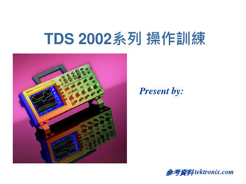
TDS 2002系列 操作訓練
Present by:
參考資料
訓練內容大綱
如何安全使用示波器
數位示波器四大系統
面板功能解說 背板功能解說
選單操作模式
測棒補償 各選單功能解說及應用
選購模組
問題與解答
安全重要的量測觀念
馬達控制 交換式電源供應器 變頻器 三相電源 不斷電系統(UPS) 程控設備
ABBDCS400直流调速器调试(工程师培训)

ABBDCS400直流调速器调试(工程师培训)ABB DCS 400 系列直流调速器自整定调试步骤参数Par No 参数功能阐述1.01Arm cur Nom(电机额定电流) 根据电机铭牌设定1.02Arm V olt Nom (电机额定电压) 根据电机铭牌设定1.03Field Cur Nom (励磁额定电流) 根据电机铭牌设定1.04Field V olt Nom(额定励磁电压) 根据电机铭牌设定1.05Base Speed (电机额定转速) 根据电机铭牌设定1.06Max Speed (电机最大转速) 根据电机铭牌设定1.10Net Under Trip=10%(主电源欠压跳闸门限)6.11DO1 Assign =10 (数字输出1的设定,无故障或报警) 6.05 AO1 Assign =1 (AO1模拟输出定义) 实际速度值6.07 AO1 Scale 100% (AO1输出信号为100%时对应的电压)如AO1接转速显示时,根据实际比列调节6.08 AO2 Assign =5 (AO2模拟输出定义) 实际电枢电流6.10 AO2 Scale 100% (AO2模拟输出定义)实际电枢电流值如AO2接电流显示时,根据实际比例调节百分比引导调试开始1 首先调到菜单Long/Short Par Ling (长短菜单选择)=Long2 选择功能菜单Commissioning(通过控制盘进入调试向导)7.01 Language (语言选择)=English >>>2.01 Macro Select (应用宏)=Standard(工厂宏)>>>1.02 Arm V olt Nom (电枢额定电压)=440V>>>1.01 Arm Cur Nom(电枢额定电流)=见电机铭牌>>>1.04 Field V olt Nom(磁场额定电压)=见电机铭牌>>>1.03 Field Cur Nom(磁场额定电流)=见电机铭牌>>>1.05 Base Speed (电机额定转速)=见电机铭牌>>>Field weakening(是否弱磁)=Yes>>>1.06 Max Speed直接按确定>>>4.06 Field Trip 直接按确定>>>2.03 Stop Ramp 直接按确定>>> 5.09 Accel Ramp 直接按确定>>> 2.04 Eme Stop Mode 直接按确定>>> Field Autotuning (励磁电流调节器自动整定)=Yes>>> Start Drive (按启动键,使电机磁场上电) 然后屏幕显示Please wait .稍等片刻后,屏幕出现Press Enter(请按确认键)。
- 1、下载文档前请自行甄别文档内容的完整性,平台不提供额外的编辑、内容补充、找答案等附加服务。
- 2、"仅部分预览"的文档,不可在线预览部分如存在完整性等问题,可反馈申请退款(可完整预览的文档不适用该条件!)。
- 3、如文档侵犯您的权益,请联系客服反馈,我们会尽快为您处理(人工客服工作时间:9:00-18:30)。
Lecture 2:Motor Model andLecture 2: Motor Model and Display SubsystemMotor Motor Battery Motor V I ωτ=−f h b Thfrom the battery. ÎThe motor current should be negative to discharge the battery.Motor Motor Battery Motor V I ωτ=−into the battery.The motor current into the battery. ÎThe motor current should be positive to charge the battery.MotorMotor Battery Motor V I ωτ=−complicated as our understanding of the complicated as our understanding of the system increases.M d l O t t(Si D i li)•Model Outputs (SimDriveline):–Motor Torque7 Place a new subsystem part (Simulink/Commonly Used Blocks)in your circuit and change the nameto “Electric_Motor.”Double-click on the subsystem block to open it:•Motor_CurrentM t C t•Motor_Diagnostics9 We also have one SimDriveline connection port(SimDriveline/Utilities).Place this part in your model and rename it as“Motor_Port.”10 We now have all of the input and output ports forWe now have all of the input and output ports forour motor model. All that is left is for us to buildthe actual model.•The inertia part is located in theSimDriveline/Solver & Inertias library.12 The inertia part specifies the inertia for all rotating parts of the motor. We will define this inertia in the init file. Double-click on the inertia part and change the value to “Motor_Inertia.”13We should find the inertia from the motor specifications ormeasure the inertia. Once a value is obtained, we will specify it in the init file:Next, we can calculate the motor current asBatteryMotorMotorMotor V I ωτ−=Use a Motion Sensor (SimDriveline/Sensors &Actuators ) to measure the motor shaft speed in r/s.14_q_–Motor torque Nm–Motor_Current_Adouble-click on the bus creator part and change the number from 2 to 3.Bus creator after makingchange.18 Complete the model as shown below.input and outputs as shown:input and outputs as shown:Top Level Block Diagram20•Connect the blocks as shown:22 The motor port is not in a convenient location to connect it to the reardiff. We can fix this problem by:•Double-clicking on the Electric_Motor subsystem to open it.•Double-clicking on the “Motor_Port” part to open its dialog box.You will see the dialog box shown next:23Double-click here.Change this to right.After making this change, we can easily connect the motor and rear diff.busses using the bus creator part busses using the bus creator part (Simulink/Commonly Used Blocks).28 Top Level Block Diagramphysical system.It is for simulation purposes physical system. It is for simulation purposes only and generates a torque request that would normally come from the vehicle’s accelerator and brake pedals.•The desired speed will be stored in a variable.•Rename the subsystem Driver. Rename the subsystem“Driver”±1.•Use the Saturation part located in the Simulink/Commonly Used Blocks library.and1and -1.•Rename the output terminal to “Driver Torque Request.”36•The saturation limits are specified asshown:as shown: as shown:create several plots to display varioussignals in different configurations.•We will also use this subsystem to logdata.We will show two methods of creating adisplay The first method will use a Scope display. The first method will use a Scopeblock. The seconds will be shown laterand use the Signal and Scope Manager.(Simulink/Commonly Used Blocks) and the Scope(Simulink/Commonly Used Blocks) to create a display of the important signals.43 Creating the Display•Double-click on the Bus Selector part •Click on the +Click on the+signs in the“Signals in theBus” windowto view theil blavailablesignals.•Select the signals in the order you want Select the signals in the order you want them to appear on the bus extractor.Selector part.•Next, double-click on the Scope part:Double-click here.47 Click on this button.•Click on the Parameters buttonChange this to 5.48Click on the Data historyTab.Click here to uncheck thisbox. Deselecting this boxbox.Deselecting this boxwill display all data in oursimulation.49 Box unchecked.Click the OK Button.Close the scopewindow and returnwindow and returnto the model.Resize the scopepart and connectthe signals.5052Set to 60.Select ode23tbSet to Auto.54Set to error.Diagnostics selected.Set to error.•These selections will highlight an algebraic if one is detected.Running the Simulation•Click the OK button.•Select Simulation and then Start from the Simulink menus or click the play button 55Simulink menus or click the play button.•It appears that we have an error.two of our subsystems The Algebraic loop two of our subsystems. The Algebraic loop is highlighted in red:57 Algebraic Loop•If you look inside the Electric_Motor subsystem, you will see the offending components in that subsystem:In order for Simulink to calculate the motor current, it needs to know the battery voltage.58 Algebraic Loop•If you look inside the Battery subsystem, you will see the offending components in that subsystem:In order to calculate the battery voltage, Simulink needs to know the motor current!information it needs to perform this information it needs to perform this calculation.part (to either the Battery model or the motor61•The memory block is a one time step delay. In the division calculation, Simulink will use the battery voltage from the previous time step. Thus the batterywill use the battery voltage from the previous time step.Thus the battery voltage is know, and Simulink can calculate the motor current.•Rerun the simulation and see if this fixes the problem.•You may want to ask yourself the question, what is the output value of the memory block at time zero (when the simulation starts)? (Obviously this implies that the block knows the input at time less than zero, which has all kinds of philosophical implications about the space-time continuum….)62•The problem is fixed, but we get anothererror.•Click on the link to jump to the error.63 According to the errormessage, this signal mustmessage,this signal mustbe Infinite, or Nan.65•For the first time step, what is the input to the Divide block?For the first time step what is the input to the Divide block?•The Memory block outputs the value from the previous time step.•For the first time step, what is the previous value.•If the block outputs a 0, we get a divide by zero, and the Divide block either outputs Inf or Nan.•We need to move the Memory block somewhere else to eliminate the algebraic loop.66Memory block removed.67 Memory block added to thebattery model.Rerun the Simulation68rpm signal.rpm signal.Demo___________ Debugging the ModelDebugging the Model72 Vehicle speedOK.Motor rpm spike.Motor rpm spike74•If there is no skidding, the tire speeds should be the same as the vehiclespeed.•Run the simulation75Zoom in here.76Tire speed same as vehicle speed.Tire speeddifferent than vehicle speed.Open the driver block and add a scope to •Open the driver block and add a scope tothe driver torque request signal.Rerun the simulation and view the scope.78 Max torque (1).Tire skiddinghappens here.Vehicle cruising gat 60 mph here.Rate Limiter80•The rate limiter places a limit on how fasta signal can increase or decrease.•The default rising and falling rates are1/second.•We will use the default values.•Since the driver torque request signal isbetween -1 and +1•Our motor will go from no torque (0)•Our motor will go from no torque(0)to full torque (1) in one second.•Our motor will go from full forwardtorque (1) to full reverse torque (-1) intwo seconds.Run a simulation with the rate limiter.81Things areworse!82 Motor rpm goingnegative.What do younotice aboutthis?•Let s plot the motor torque using a scope.Let’s plot the motor torque using a scopeRate limiterremoved.84 Scope added.85Tire skiddinghappens here.h hZoom in on thissection.86Traces in natureare very rarelystraight. Usuallythings are curved.Zoom in someZoom in somemore.87Simulation point.Simulation point.pLooks like at i ht listraight lineconnecting twosimulation points.Model Debugging•Another hint comes from the MATLAB command window.88What is this?p glike we had a step of 0.35 seconds that was too large.•Let’s try a smaller step size.•Select Simulation and then Configuration Parameters from the Simulink menus.•Change the Max Step size from Auto to 0.01 (seconds)90This was set to Auto.Change it to 0.01.•This parameter specifies that the maximum time between simulation points will be 0.01 seconds. (It between simulation points will be001seconds(Itcan be smaller if necessary.)•Rerun the simulation with this change.91 and negative battery voltages.•How does our model breakdown if the motor current is too large?Demo___________。