机械毕业设计英文外文翻译436手动变速器 (2)
机械毕业设计英文外文翻译444手动变速器如何工作
附录How Manual Transmissions WorkIf you drive a stick-shift car, then you may have several questions floating in your head.How does the funny "H" pattern that I am moving this shift knob through have any relation to the gears inside the transmission? What is moving inside the transmission when I move the shifter?When I mess up and hear that horrible grinding sound, what is actually grinding? What would happen if I were to accidentally shift into reverse while I am speeding down the freeway? Would the entire transmission explode?In this article, we'll answer all of these questions and more as we explore the interior of a manual transmission.Cars need transmissions because of the physics of the gasoline engine. First, any engine has a redline --a maximum rpm value above which the engine cannot go without exploding. Second, if you have read How Horsepower Works, then you know that engines have narrow rpm ranges where horsepower and torque are at their maximum. For example, an engine might produce its maximum horsepower at 5,500 rpm. The transmission allows the gear ratio between the engine and the drive wheels to change as the car speeds up and slows down. You shift gears so the engine can stay below the redline and near the rpm band of its best performance.Ideally, the transmission would be so flexible in its ratios that the engine could always run at its single, best-performance rpm value. That is the idea behind the continuously variable transmission (CVT).A CVT has a nearly infinite range of gear ratios. In the past, CVTs could not compete with four-speed and five-speed transmissions in terms of cost, size and reliability, so you didn't see them in production automobiles. These days, improvements in design have made CVTs more common. The Toyota Prius is a hybrid car that uses a CVT.The transmission is connected to the engine through the clutch. The input shaft of the transmission therefore turns at the same rpm as the engine.A five-speed transmission applies one of five different gear ratios to the input shaft toproduce a different rpm value at the output shaft.A Very Simple TransmissionTo understand the basic idea behind a standard transmission, the diagram below shows a very simple two-speed transmission in neutral:Let's look at each of the parts in this diagram to understand how they fit together:The green shaft comes from the engine through the clutch. The green shaft and green gear are connected as a single unit. (The clutch is a device that lets you connect and disconnect the engine and the transmission. When you push in the clutch pedal, the engine and the transmission are disconnected so the engine can run even if the car is standing still. When you release the clutch pedal, the engine and the green shaft are directly connected to one another. The green shaft and gear turn at the same rpm as the engine.) The red shaft and gears are called the layshaft. These are also connected as a single piece, so all of the gears on the layshaft and the layshaft itself spin as one unit. The green shaft and the red shaft are directly connected through their meshed gears so that if the green shaft is spinning, so is the red shaft. In this way, the layshaft receives its power directly from the engine whenever the clutch is engaged.The yellow shaft is a splined shaft that connects directly to the drive shaft through the differential to the drive wheels of the car. If the wheels are spinning, the yellow shaft is spinning.The blue gears ride on bearings, so they spin on the yellow shaft. If the engine is offbut the car is coasting, the yellow shaft can turn inside the blue gears while the blue gears and the layshaft are motionless.Now, let's see what happens when you shift into first gear.First GearIn this picture, the green shaft from the engine turns the layshaft, which turns the blue gear on the right. This gear transmits its energy through the collar to drive the yellow drive shaft. Meanwhile, the blue gear on the left is turning, but it is freewheeling on its bearing so it has no effect on the yellow shaft.When the collar is between the two gears (as shown in the first figure), the transmission is in neutral. Both of the blue gears freewheel on the yellow shaft at the different rates controlled by their ratios to the layshaft.From this discussion, you can answer several questions:When you make a mistake while shifting and hear a horrible grinding sound, you are not hearing the sound of gear teeth mis-meshing. As you can see in these diagrams, all gear teeth are all fully meshed at all times. The grinding is the sound of the dog teeth trying unsuccessfully to engage the holes in the side of a blue gear.The transmission shown here does not have "synchros" (discussed later in the article), so if you were using this transmission you would have to double-clutch it. Double-clutching was common in older cars and is still common in some modern race cars. In double-clutching, you first push the clutch pedal in once to disengage the engine from the transmission. This takes the pressure off the dog teeth so you can move the collar into neutral. Then you release the clutch pedal and rev the engine to the "right speed." The right speed is the rpm value at which the engine should be running in the next gear. The idea is to get the blue gear of the next gear and the collar rotating at the same speed so that the dog teeth can engage. Then you push the clutch pedal in again and lock the collar into the new gear. At every gear change you have to press and release the clutch twice, hence the name "double-clutching."You can also see how a small linear motion in the gear shift knob allows you to change gears. The gear shift knob moves a rod connected to the fork. The fork slides the collar on the yellow shaft to engage one of two gears.In the next section, we'll take a look at a real transmission.A Real TransmissionThere are three forks controlled by three rods that are engaged by the shift lever. Looking at the shift rods from the top, they look like this in reverse, first and second gear: Keep in mind that the shift lever has a rotation point in the middle. When you push the knob forward to engage first gear, you are actually pulling the rod and fork for first gear back.You can see that as you move the shifter left and right you are engaging different forks (and therefore different collars). Moving the knob forward and backward moves the collar to engage one of the gears。
汽车手动变速箱外文及其部份翻译
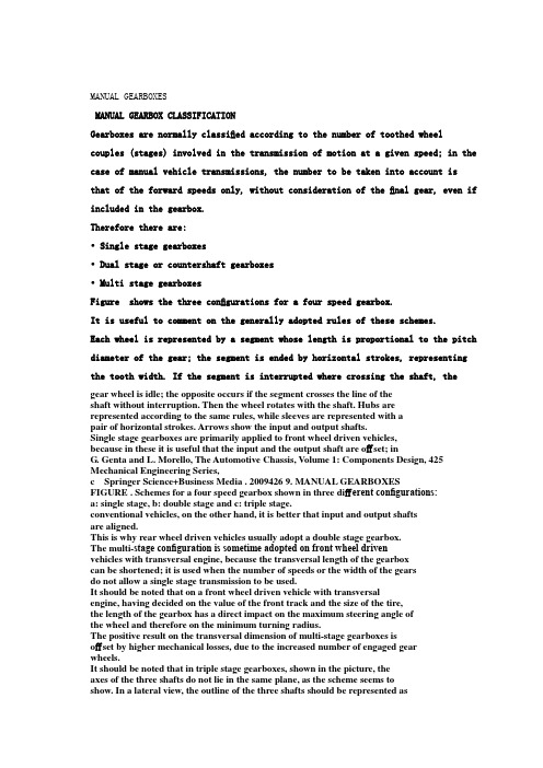
MANUAL GEARBOXESMANUAL GEARBOX CLASSIFICATIONGearboxes are normally classified according to the number of toothed wheel couples (stages) involved in the transmission of motion at a given speed; in the case of manual vehicle transmissions, the number to be taken into account isthat of the forward speeds only, without consideration of the final gear, even if included in the gearbox.Therefore there are:• Single stage gearboxes• Dual stage or countershaft gearboxes• Multi stage gearboxesFigure shows the three configurations for a four speed gearbox.It is useful to comment on the generally adopted rules of these schemes.Each wheel is represented by a segment whose length is proportional to the pitch diameter of the gear; the segment is ended by horizontal strokes, representing the tooth width. If the segment is interrupted where crossing the shaft, the gear wheel is idle; the opposite occurs if the segment crosses the line of theshaft without interruption. Then the wheel rotates with the shaft. Hubs arerepresented according to the same rules, while sleeves are represented with apair of horizontal strokes. Arrows show the input and output shafts.Single stage gearboxes are primarily applied to front wheel driven vehicles,because in these it is useful that the input and the output shaft are offset; inG. Genta and L. Morello, The Automotive Chassis, Volume 1: Components Design, 425 Mechanical Engineering Series,c Springer Science+Business Media . 2009426 9. MANUAL GEARBOXESFIGURE . Schemes for a four speed gearbox shown in three different configurations:a: single stage, b: double stage and c: triple stage.conventional vehicles, on the other hand, it is better that input and output shaftsare aligned.This is why rear wheel driven vehicles usually adopt a double stage gearbox.The multi-stage configuration is sometime adopted on front wheel drivenvehicles with transversal engine, because the transversal length of the gearboxcan be shortened; it is used when the number of speeds or the width of the gearsdo not allow a single stage transmission to be used.It should be noted that on a front wheel driven vehicle with transversalengine, having decided on the value of the front track and the size of the tire,the length of the gearbox has a direct impact on the maximum steering angle ofthe wheel and therefore on the minimum turning radius.The positive result on the transversal dimension of multi-stage gearboxes isoffset by higher mechanical losses, due to the increased number of engaged gearwheels.It should be noted that in triple stage gearboxes, shown in the picture, theaxes of the three shafts do not lie in the same plane, as the scheme seems toshow. In a lateral view, the outline of the three shafts should be represented asthe vertices of a triangle; this lay-out reduces the transversal dimension of thegearbox. In this case and others, as we will show later, the drawing is representedby turning the plane of the input shaft and of the counter shaft on the plane ofthe counter shaft and of the output shaft.Gear trains used in reverse speed are classified separately. The inversion ofspeed is achieved by using an additional gear. As a matter of fact, in a train ofthree gears, the output speed has the same direction as the input speed, whilethe other trains of two gears only have an output speed in the opposite direction;the added gear is usually called idler.The main configurations are reported in Fig. .In scheme a, an added countershaft shows a sliding idler, which can matchtwo close gears that are not in contact, as, for example, the input gear of thefirst speed and the output gear of the second speed. It should be noted that, inthis scheme, the drawing does not preserve the actual dimension of the Manual gearbox classification 427FIGURE . Schemes used for reverse speed; such schemes fit every type of gearboxlay-out.Scheme b shows instead two sliding idlers, rotating together; this arrange-ment offers additional freedom in obtaining a given transmission ratio. The coun-tershaft is offset from the drawing plane; arrows show the gear wheels that matchwhen the reverse speed is engaged.Scheme c is similar to a in relation to the idler; it pairs an added specificwheel on the output shaft with a gear wheel cut on the shifting sleeve of the firstand second speed, when it is in idle position.Configuration d shows a dedicated pair of gears, with a fixed idler and ashifting sleeve.The following are the advantages and disadvantages of the configurationsshown in the figure.•Schemes a, b and c are simpler, but preclude the application of synchro-nizers (because couples are not always engaged), nor do they allow the useof helical gears (because wheels must be shifted by sliding).•Scheme d is more complex but can include a synchronizer and can adopthelical gears.•Schemes a, b and c do not increase gearbox 9. MANUAL GEARBOXESMECHANICAL EFFICIENCYThe mechanical efficiency of an automotive gear wheel transmission is high com-pared to other mechanisms performing the same function; indeed, the value ofthis efficiency should not be neglected when calculating dynamic performanceand fuel consumption. The continuous effort of to limit fuel consumption justi-fies the care of transmission designers in reducing mechanical losses.Total transmission losses are conveyed up by terms that are both dependentand independent of the processed power; the primary terms are:•Gearing losses; these are generated by friction between engaging teeth(power dependent) and by the friction of wheels rotating in air and oil(power independent).•Bearing losses; these are generated by the extension of the contact area ofrolling bodies and by their deformation (partly dependent on and partlyindependent of power) and by their rotation in the air and oil (powerindependent).•Sealing losses; they are generated by friction between seals and rotatingshafts and are power independent.•Lubrication losses; these are generated by the lubrication pump, if present,and are power independent.All these losses depend on the rotational speed of parts in contact and,therefore, on engine speed and selected transmission ratio.Table reports the values of mechanical efficiency to be adopted in calcu-lations considering wide open throttle conditions; these values consider a pair ofgearing wheels or a complete transmission with splash lubrication; in the sametable we can see also the efficiency of a complete powershift epicycloidal auto-matic transmission and a steel belt continuously variable transmission. For thetwo last transmissions, the torque converter must be considered as locked-up.TABLE . Mechanical efficiency of different transmission mechanisms.Mechanism type Efficiency (%)Complete manual gearboxwith splash lubrication 92–97Complete automatic transmission(ep. gears) 90–95Complete automatic gearbox(steel belt; without press. contr.) 70–80Complete automatic gearbox(steel belt; with press. contr.) 80–86Pair of cyl. gears –Pair of bevel gears 90– Mechanical efficiency 429FIGURE . Contributions to total friction loss of a single stage gearbox designed for300 Nm as function of input speed.It is more correct to reference power loss measurement as a function ofrotational input speed rather than efficiency. Figure shows the example ofa double stage transmission, in fourth speed, at maximum power; the differentcontributions to the total are shown.This kind of measurement is made by disassembling the gearbox step bystep, thus eliminating the related loss.In the first step all synchronizer rings are removed, leaving the synchronizerhubs only; mechanical losses of non-engaged synchronizers are, therefore, mea-surable. The loss is due to the relative speed of non-engaged lubricated conicalsurfaces; the value of this loss depends, obviously, on speed and the selectedtransmission ratio.In the second step all rotating seals are removed.In the third step the lubrication oil is removed, and therefore, the bulk ofthe lubrication losses is eliminated; some oil must remain in order to leave thecontact between teeth unaffected.By removing those gear wheels not involved in power transmission, theirmechanical losses are now measurable.The rest of the loss is due to bearings; the previous removal of parts canaffect this value.A more exhaustive approach consists in measuring the complete efficiencymap; the efficiency can be represented as the third coordinate of a surface, wherethe other two coordinates are input speed and engine torque. Efficiency calcu-lations can be made by comparing input and output torque of a working trans-mission.Such map can show how efficiency reaches an almost constant value at amodest value of the input torque; it must not be forgotten that standard fuelconsumption evaluation cycles involve quite modest values of torque and there-fore imply values of transmission efficiency that are changing with torque.Figure shows a qualitative cross section of the aforesaid map, cut atconstant engine speed. It should be noted that efficiency is also zero at input430 9. MANUAL GEARBOXESFIGURE . Mechanical efficiency map, as a function of input torque at constantengine speed; the dotted line represents a reasonable approximation of this curve, to beused on mathematical models for the prediction of performance and fuel consumption.torque values slightly greater than zero; as a matter of fact, friction implies acertain minimum value of input torque, below which motion is impossible.A good approximation to represent mechanical efficiency can be made usingthe dotted broken line as an interpolation of the real curve.MANUAL AUTOMOBILE GEARBOXES9.3.1 Adopted schemesIn manual gearboxes, changing speed and engaging and disengaging the clutchare performed by driver force only.This kind of gearbox is made with helical gears and each speed has a syn-chronizer; some gearboxes do not use show the synchronizer for reverse speed,particularly those in economy minicars.We previously discussed a first classification; additional information is thespeed number, usually between four and six.Single stage gearboxes are used in trans-axles; they are applied, with someexceptions, to front wheel driven cars with front engine and rear driven cars withrear engine; this is true with longitudinal and transversal engines.In all these situations the final drive is included in the gearbox, which istherefore also called transmission.Countershaft double stage gearboxes are used in conventionally driven cars,where the engine is mounted longitudinally in the front and the driving axle isthe rear axle. If the gearbox is mounted on the rear axle, in order to improve theweight distribution, the final drive could be included in the Manual automobile gearboxes 431 By multi-stage transmissions, some gear wheels could be used for differentspeeds. The number of gearing wheels could increase at some speeds; this nor-mally occurs at low speeds, because the less frequent use of these speeds reducesthe penalty of lower mechanical efficiency on fuel consumption.Cost and weight increases are justified by transmission length reduction,sometimes necessary on transversal engines with large displacement and morethan four cylinders.In all these gearboxes synchronizers are coupled to adjacent speeds .:first with second, third with fourth, etc.) in order to reduce overall length andto shift the two gears with the same selector rod.We define as the selection plane of a shift stick (almost parallel to the xzcoordinate body reference system plane for shift lever on vehicle floor) the planeon which the lever knob must move in order to select two close speed pairs. Forinstance, for a manual gearbox following many existing schemes, first, second,third, fourth and fifth speed are organized on three different selection planes; thereverse speed can have a dedicated plane or share its plane with the fifth speed.Figure shows a typica l example of a five speed single stage gearbox. Thefirst speed wheels are close to a bearing, in order to limit shaft deflection.In this gearbox the total number of tooth wheels pairs is the same as forthe double stage transmission shown in Fig. .While in the first gearbox there are only two gearing wheels for each speed,in the second there are three gearing wheels for the first four speeds and noneFIGURE . Scheme for a five speed single stage transmission, suitable for front wheeldrive with transversal 9. MANUAL GEARBOXESFIGURE . Scheme of an on-line double stage gearbox for a conventional lay-out.for the fifth. This property is produced by the presence of the so called constantgear wheels (the first gear pair at the left) that move the input wheels of t hefirst four speeds; the fifth speed is a direct drive because the two parts of theupper shaft are joined together.The single stage gearbox in Fig. shows the fifth speed wheel pair posi-tioned beyond the bearing, witness to the upgrading of an existing four speed transmission; in this case the fifth speed has a dedicated selection plane.The double stage gearbox in Fig. is organized in a completely differentway but also shows the first speed pair of wheels close to the bearing. The directdrive is dedicat ed to the highest speed; the fifth speed shows a dedicated selectionplane.Six speed double stage gearboxes do not show conceptual changes in com-parison with the previous examples; synchronizers are organized to leave firstand second, third and fourth, fifth and sixth speeds on the same selection plane.As already seen, the multistage configuration shown in Fig. allows areasonable reduction of the length of the gearbox. In this scheme, only first andsecond speeds benefit from the second countershaft; power enters the counter-shaft through a constant gear pair of wheels and flows to the output shaft at areduced speed. Third, fourth and fifth speed have a single stage arrangement.Reverse speed is obtained with a conventional idling wheel.9.3.2 Practical examplesFour speed gearboxes represented the most widely distributed solution in Europeuntil the 1970s, with some economy cars having only three Manual automobile gearboxes 433 FIGURE . Scheme of a triple stage five speed gearbox, suitable for front wheel drivencar with transversal engine.With the increase in installed power, the improvement in aerodynamic per-formance and increasing attention to fuel consumption, it became necessary toincrease the transmission ratio of the last speed, having the first s peed remain atthe same values; as a matter of fact car weight continued to increase and engineminimum speed did not change significantly.To achieve satisfactory performance all manufacturers developed five speedgearboxes; this solution is now standard, but many examples of six speed gear-boxes are available on the market, not limited to sports cars.Figure shows an example of a six speed double stage transmission withthe fifth in direct drive; here the first and second pair of wheels are close to thebearing.This rule is not generally accepted; on one hand having the most stressedpairs of wheels close to the bearing allows a shaft weight containment. On theother hand, having the most frequently used pairs of wheels close to the bearingreduces the n oise due to shaft deflection.Synchronizers of fourth and third speed are mounted on the countershaft;this lay-out reduces the work of synchronization, improving shifting quality by anamount proportional to the dimension of the synchronizing rings. Synchronizersof first and second gear on the output shaft are, because of their diameter, larger434 9. MANUAL GEARBOXESFIGURE . Double stage six speed gearbox (GETRAG).than those of the corresponding gear; the penalty of the synchronization work ispaid by the adoption of a double ring synchronizer.Synchronizers on the countershaft offer a further advantage: In idle positionthe gears are stopped and produce no rattle; this subject will be studied later Manual automobile gearboxes 435Figure introduces the example of a single stage gearbox for a frontlongitudinal engine. The input upper shaft must jump over the differential, whichis set between the engine and the wheels. The increased length of the shaftssuggested adopting a hollow section. Because of this length the box is dividedinto two sections; on the joint between the two sections of the box additionalbearings are provided to reduce the shaft deflection.The input shaft features a ball bearing close to the engine and three otherneedle bearings that manage solely the radial loads. The output shaft has twotapered roller bearings on the differential side and a roller bearing on the oppositeside. This choice is justified by the relevant axial thrust emerging from the bevelgears.The first and second speed synchronizers are on the output shaft and featurea double ring.The reverse speed gears are placed immediately after the joint (the idlergear is not visible) and have a synchronized shift. Remaining synchronizers areset in the second section of the box on the input shaft. The output shaft endswith the bevel pinion, a part of the final ratio.It should be noted that the gears of the first, second and reverse speeds aredirectly cut on the input shaft, in order to reduce overall dimensions.Most contemporary cars use a front wheel drive with transversal engine; thenumber of gearboxes with integral helical final ratio is, therefore, dominant.In these gearboxes geared pairs are mounted from the first to the last speed,starting from the engine side. An example of this architecture is given in Fig. .Like many other transmissions created with only four speeds, it shows thefifth speed segregated outside of the aluminium box and enclosed by a thin steelsheet cover; this placement is to limit the transverse dimension of the powertrain, in the area where there is potential interference with the left wheel in thecompletely steered position.This solution is questionable as far as the total length is concerned but showssome advantage in the reduction of the span between the bearings. Each bearingis of the ball type; on the side opposite to the engine the external ring of thebearing can move axially, to compensate for thermal differential displacements.One of the toothed wheels of the reverse speed is cut on the fir st and secondshifting sleeve.The casing is open on both sides; one of these is the rest of one of thebearings of the final drive. A large cover closes the casing on the engine side and,in the meantime, provides installation for the second bearing of the final driveand the space for the clutch mechanism; it is also used to join the gearbox tothe engine.In this gearbox synchronizers are placed partly on the input shaft and partlyon the output shaft.Figure shows a drawing of a more modern six speed gearbox, in whichit was possible to install all the gears in a conventional single stage arrangement,thanks to the moderate value of the rated 9. MANUAL GEARBOXESFIGURE . Single stage six speed gearbox for longitudinal front engine (Audi). Manual gearboxes for industrial vehicles 437FIGURE . Five speed transmission for a transversal front engine (FIAT).Gears are arranged from the first to the sixth, starting from the engineside; as we have already said this arrangement is demanded by the objectiveof minimizing shaft deflection. Only the synchronizers of first and second speedfound no place on the input shaft; they are of the double ring type, as for thefirst speed.The reverse speed is synchronized and benefits of a countershaft not shownin this drawing.MANUAL GEARBOXES FOR INDUSTRIALVEHICLES9.4.1 Lay-out schemesThe gearboxes we are going to examine in this section are suitable for vehicles ofmore than about 4 t of total weight; lighter vehicles, usually called commercialvehicles, adopt gearboxes that are derived from automobile production, as notedin the previous 9. MANUAL GEARBOXESFIGURE . Six speed transmission for a transversal front engine (FIAT).Gearboxes used in industrial vehicles also feature synchronizers; they can beshifted directly, as in a conventional manual transmission, or indirectly with theassistance of servomechanisms. Non-synchronized gearboxes are sometimes usedon long haul trucks, because of their robustness. Assisted shifting mechanismsare widespread because of the easy availability of power media. Automatic orsemi-automatic transmissions are also used, the first type especially in buses.For gearboxes with four up to six speeds, the double stage countershaftarchitecture represents a standard; the scheme is the same as seen before.The constant gear couple is used for all speeds but the highest. Also notableis that the lowest speed wheels are close to the bearings.As shown in the drawings of Fig. , the highest speed can be obtainedeither in direct drive (scheme b) or with a pair of gears (scheme a); in this lastcase the direct drive is used for the speed before the last: these architectures arecalled direct drive and overdrive.In the figure, only the last and the first before the last speed are represented.The cho ice between the two alternatives can be justified by the differentvehicle mission; virtually the same gearbox can be used on different vehicleswith different frequently used speeds (a truck and a bus for example). Manual gearboxes for industrial vehicles 439FIGURE . Alternative constant gear schemes with last or first before the last speedin direct drive.Sometime the constant gear is set on the output shaft, after the differentspeed gears; this configuration offers the following advantages:•Reduction of the work of synchronization, because of the smaller gear di-mension at the same torque and total transmission ratio•Less stress on the input shaft and countershaftOn the other hand, the following disadvantages emerge:•Bearings rotate faster.•Constant gear wheels are more highly stressed.This applies for single range transmissions.Multiple range transmissions feature, in addition to the main gearbox, othergearboxes that multiply the number of speeds of the main gearbox by the numberof their speeds. With this architecture the total number of gear pairs might bereduced, for a given number of speeds, and, sometime the use of the gearshiftlever can be simpler.This arrangement is used when more than six speeds are necessary. A multi-ple range transmission is therefore made out of a combination of different coun-tershaft gearboxes, single range gearboxes or epicycloidal gearboxes.Each added element is called a range changer if it is conceived as beingcapable of using the main gearbox speeds in sequence, in two completely non-overlapping series of vehicle speeds; for example, if the main gearbox has fourspeeds, the first speed in the high range is faster than the fourth speed in thelow range.The element is called a splitter if it is intended to create speeds that areintermediate to those of the main gearbox; in this case, for example the third440 9. MANUAL GEARBOXESFIGURE . Scheme of a 16 speed gearbox for industrial vehicles; it is made with afour gear main gearbox, a double speed splitter and a double speed range changer withdirect drive.speed in the high range is faster than the third speed in the low range, but slowerthan the fourth speed in the low range.We call the gearbox with the highest number of speeds the main gearbox;the splitter and the range changer will be set in series before and after the maingearbox.Figure shows the scheme of a gearbox featuring a splitter and a rangechanger. The splitter is made out of a pair of wheels that work as two differentconstant gears for the main gearbox. The countershaft can therefore be movedat two different speeds, according to the position of the splitter unit. Becausethe main gearbox has four speeds, this splitter unit can create a total of eightspeeds, one of them being in direct drive.At the output shaft of this assembly, there is a range changer unit madeas a two speed double stage gearbox with direct drive; this unit multiplies by two the total number of obtainable speeds. The range changer is qualified by the significant difference between the two obtainable speeds.The range changer can be made with a countershaft gearbox or an epicy- cloidal gearbox with direct drive; the advantage in the latter case is the possi- bility of an easier automatic actuation, by braking some of the elements of the epicycloidal Manual gearboxes for industrial vehicles 441FIGURE . Transmission ratios obtained with the scheme of transmission shown in Fig. ; speed identification shows the main gearbox speed with the number, the splitter position with the first letter, the range changer position with the second; L stands for low, H stands for high.It is also possible to place the range changer before the main gearbox andthe splitter unit after the main gearbox.A different way of defining the functions of r ange change units is to say thatthe splitter is a gearbox that compresses the gear sequence, because it reduces the gap between speeds, while the range changer is a gearbox that expands the gear sequence, because it increases the total range of the transmission.Figure explains the concept of compression; the bars represent the ratios obtained in all shifting lever positions. Ratios obtained with the splitter unit in the L position (the first letter in the speed identification, L stands for lower ratio) are interspersed with the ratios obtained with the splitter unit in the H position (H stands for higher ratio, in this case 1:1) and reduce the amplitude of the gear steps of the main gearbox.The same figure also explains the concept of expansion, showing on thesame graph the ratio obtained with the range changer in the H position (second identification letter) and the L position; the gear step between the first in low gear and the first in high gear is as big as the range of the main gearbox, andthe total transmission range is widened.The range changer is therefore seldom used, when driving conditions change suddenly, as, for example, when leaving a normal road for a country road that must be driven more slowly, or when encountering a strong slope with a fully loaded vehicle. The splitter allows the dynamic performance of the vehicle to be improved, making the optimum transmission ratio available to obtain the desired power. The splitter is therefore used frequently. In a fully loaded vehicle, for example, all split ratios can be used in sequence during full throttle acceleration from a 9. MANUAL GEARBOXESThe range changer and splitter are usually made as modular units that canbe mounted at both ends of the main gearbox, or changed with simple covers,in order to satisfy all application needs with limited total production costs. Generalizing these concepts could suggest building transmissions using ad- ditional range changing units arranged in series. These could be conceived as being made only of splitter units with direct drive.In such a case, with n pairs of tooth wheels it is possible to obtain a totalof z transmission ratios, given by the formula:z =2n−1.The formula expresses the number of possible states that can be obtainedfrom n − 1 pairs of gears; one unit is subtracted because one pair must be a constant gear to move the countershaft.With four pairs of gears, for example, four speeds can be obtained in adouble stage gearbox; while using a cascade of splitters eight different speeds could be obtained. The goal of good shift manoeuvrability and the implications for mechanical losses must not be forgotten, while defining the best architecture. Figure shows the scheme of the 16 speed transmission with splitter and。
外文翻译:手动变速器概述

Manual transmissionManual transmission is the most basic of transmission of a type, its effect is changing, and provide the transmission reverse and neutral. Usually, the pilot on the clutch pedal through manipulation and in any HuanDangGan can choose between gear. There are a few manual transmission, such as motorcycles, cars, some transmission shift transmission allows only sequence, the transmission is called sequence shift transmission. In recent years, along with the electronic control components durability, computerized automatic switching clutch automatic shift of transmission in Europe since the start line are more and more popular, car V olkswagen and ford are sold in the city on the double clutch provide updated generation, transmission from the start with two clutches, every shift automatically switch to another group of clutch engagement, need not as quick as traditional in manual have only one group separated again clutch engagement, shifting speed is faster, more small change gear vibration.Internal structure: shaftDecorate a form of transmission shaft type usually have two and three shaft type two kinds. Usually a rear wheel drive car will adopt three axis type, i.e. input shaft transmission, the output shaft and oart. Input shaft front associated with engine, borrow clutch output shaft back-end through the flange and universal transmission device connected.Input shaft and the output shaft in the same horizontal line, with their oart parallel arrangement. From the input shaft power through the gears to preach to the output shaft oart again. In many input and output shaft transmission shaft could engage in together, so to power, then the gear oart called directly. Direct files through uniaxial transmission, the ratio of 1:1, the highest transmission efficiency. Even in the transmission directly, cannot offer the input shaft, and the output shaft is decorated in a straight line to reduce work needed to inherit the torque transmission.Reversing deviceGenerally speaking, the reverse gear reducer than can alsosynchronizerIn synchronized meshing gears have type synchronizer Settings, can make two gear engagement in the first, before the speed reached synchronizer in all of this manual geartransmission of the car has been usedClutch,The clutch is can make two gear with a separate with mechanical parts, two gear transmission power can be combined, but when to speed, so will depend on the first two gear clutch, change gear ratio, the two gear transmission power, continue again Control:GearIn simple terms, the high speed, low speed ShengDang when the time cameEvery car high speedCompared with automatic transmissionThis refers to the automatic transmission of traditional hydraulic transmission, namely through hydraulic torque converter and planetary gear transmission power automatic transmission.Advantages:transmission efficiency than automatic gearboxes for high, of course, theoretically can compare economical.maintenance will be cheaper than transmission.If you want to higher cost, can begin from both the row of convenience and high power手动变速器手动变速器是汽车变速器中最基本的一种类型,其作用是改变传动比,并提供倒档和空档。
中英文文献翻译-手动变速器

附录外文文献Manual transmission is the most basic of transmission of a type, its effect is changing, and provide the transmission reverse and neutral. Usually, the pilot on the clutch pedal through manipulation and in any HuanDangGan can choose between gear. There are a few manual transmission, such as motorcycles, cars, some transmission shift transmission allows only sequence, the transmission is called sequence shift transmission. In recent years, along with the electronic control components durability, computerized automatic switching clutch automatic shift of transmission in Europe since the start line are more and more popular, car Volkswagen and ford are sold in the city on the double clutch provide updated generation, transmission from the start with two clutches, every shift automatically switch to another group of clutch engagement, need not as quick as traditional in manual have only one group separated again clutch engagement, shifting speed is faster, more small change gear vibration.Internal structure: shaftDecorate a form of transmission shaft type usually have two and three shaft type two kinds. Usually a rear wheel drive car will adopt three axis type, i.e. input shaft transmission, the output shaft and oart. Input shaft front associated with engine, borrow clutch output shaft back-end through the flange and universal transmission device connected.Input shaft and the output shaft in the same horizontal line, with their oart parallel arrangement. From the input shaft power through the gears to preach to the output shaft oart again. In many input and output shaft transmission shaft could engage in together, so to power, then the gear oart called directly. Direct files through uniaxial transmission, the ratio of 1:1, the highest transmission efficiency. Even in the transmission directly, cannot offer the input shaft, and the output shaft is decorated in a straight line to reduce work needed to inherit the torque transmission.Reversing deviceGenerally speaking, the reverse gear reducer than can alsosynchronizerIn synchronized meshing gears have type synchronizer Settings, can make two gear engagement in the first, before the speed reached synchronizer in all of this manual gear transmission of the car has been usedClutch,The clutch is can make two gear with a separate with mechanical parts, two gear transmission power can be combined, but when to speed, so will depend on the first two gear clutch, change gear ratio, the two gear transmission power, continue againControl:GearIn simple terms, the high speed, low speed ShengDang when the time came Every car high speedCompared with automatic transmissionThis refers to the automatic transmission of traditional hydraulic transmission, namely through hydraulic torque converter and planetary gear transmission power automatic transmission.Advantages: transmission efficiency than automatic gearboxes for high, of course, theoretically can compare economical.maintenance will be cheaper than transmission.If you want to higher cost, can begin from both the row of convenience and high power附录外文文献的中文翻译手动变速器是汽车变速器中最基本的一种类型,其作用是改变传动比,并提供倒档和空档。
机械外文翻译文献翻译无级变速器
英文原文Stepless speed technologyStepless spee d tee 加ology USES belt and the work of the Lord diameters driven pulley, cooperated with the power to deliver, can realize the TRANSMISSION ratio of the continuous change, and get the TRANSMISSION and engine condition the best match between. Common step-l ess transmission have hydraulic mech 皿cal step-less transmission and belt type step-less transmission, the current domestic market of the vehicles already more and more. Editor this section step-less transmission and the origin of the automatic transmissionAutomatic transmission i s easy to operate, reduce fatigue driving, born of the gear drive system, the control method, it can be divided into the hydraulic controlled hydraulic and electric automatic transmission hydraulic automatic transmission; According to the change of the transmission way and can be divided into have levels o f automatic transmission and no levels of automatic transmission. Ther efore, step-less transmission is actually a kind of automatic transmission, but it than common automatic transmission is much more complex, more advanced tec 血ol ogi es. Step-less transmission and common hydraulic automatic transmission of the biggest differences is on the structure, the latter is by hydraulic control gear 如ve system structure, still have the gears, it can be realized in betwe en the two block is continuously variable transmission, and is two groups plate and a belt speed o f than traditional automatic transmission, simple structure, smaller. In addition, it is free to change gear ratios, so as to realize the full speed stepless speed change, make more smoothly, without the traditional transmission shift at the'"'feeling. Editor this section step-l ess transmission classificationTo realize stepless speed, 如ving mode can be adopted according to the liquid transmission, power transmission and mech皿cal drive three ways.Liquid transmissionLiquid transmission is divided into two kinds: one kind is hydraulic, mainly is composed by the pump and motor or the valve and pump v缸able speed of transmission device, apply to small and medium-sized power transmission. Another kind is hydraulic type, adopts hydraulic coupler or hydraulic torque of variable speed drive, used in high power(kw)To hundreds of thousands of Th e main characteristics of liquid transmission is: spee d range, can absorb the impact and big to prevent transmission efficiency high, overload, long life, easy to realize automation: manufacturing precision demand is high, the price is more expensive, output characteristics for constant torque, sliding rate is bigger, running vulnerable to leak.Po wer transmissionPo wer transmission basically is divided into three categories: one kind is electromagnetic sliding type, it is in the asynchronous motor installed in electromagnetic clutch, sliding by changing i ts exciter current to speed, this belongs to a kind of relatively bac kwardspeed adjustment way. T hecharacteristics of simple structure, low cost, convenient operation and maintenance, sliding, low efficiency, biggest fever, not suitable for long-term serious load operation, the general used only for small power transmission. Second is the dc motor type, changes in the magnetic flux or change the armature voltage realize the speed. Its characteristic is speed range, high precision, large and comp l ex, high cost but equipment, maintenance difficu l ties, are used for medium power range (dozens to hundreds of kw), has gradually been ac motor type instead. T hree kinds of ac motor type is, through the change pole, pressure control and frequency conversion for the speed. The most practical application for variable frequency speed regulation, namely deserve using a horns, and then get l uffing power drive motor variable speed. Its characteristic is the speed performance is good, range, high efficiency, it can automatic control, small volume, it is suitable for a wide range of power: mechanical properties in single reducing speed constant torque, low efficiency and low speed running smooth enough, the price is higher, maintenance should be professional. In recent years, frequency converter as an advanced, excellent variab l e speed device rapid development of machinery, step-less transmission produced a certain impactMechanical transmissionThe main characteristic of the mechanical transmission is stable, rotate speed sliding rate, reliable, and has small constant power mechanical properties, the transmission efficiency is high, and simp l e structure, convenient maintenance, the price is relatively cheap; B ut parts processing and lubrication to demand higher bearing capacity, low resistance, resistance to 皿pact overload and poor, so general suitable for medium and small power transmission.1, MTThe manual transmission(MT: Manua l Transmission) gearset, because the number of teeth of each gear is fixed, each gear ratio is a fixed value (that is, the so-called "level"). For example, a block ratio of 3.455, the second gear is 2.056 to the five-speed 0.85, these figures are multiplied by the main reduction ratio is the total transmission ratio of the power train, 5-speed transmission 5 value (ie 5 level), so it is a step-variable transmission. The manual transmission is the most common transmission, composed of relatively AT and CVT, its structure is simple, the main axis of the input shaft, output shaft and the intermediate shaft, the shaft bearings, each gear, the synchronizer, the shift operating mechanism. Manual transmission failure rate is relatively low, the use of lower cost.2,ATAutomatic transmission (A T: Automatic Transmission) automatic upshifts and downs皿s lifting gear control, computer based primarily on speed and load (throttle pedal stroke), but also refer to a variety of signal transmission oil temperature, shift mode. The same point of the AT and MT both step-variable transmission, only that the A T has a continuous speed ratio variation in the respective gear, and the speed according to the vehicle speed automatically to achieve a gear change for hand can be eliminated block cars "frustrated" variable block feeling. (1) AT structure: Compared with manual wave, hydraulic automatic transmission (AT) are very different in structure and use.Manually waves mainly composed of gears and shafts, v 印able speed torque generated by different gear combinations; AT by the torque converter, a planetary gear and the hydraulic steering system, to achieve a v印able speed hydraulic transmission and gear combination moment. Wherein the torque converter is the most characteristic parts of the A T, it is composed by the pump impeller, turbine and guide wheel member, directly enter the engine power transmitting torque and clutch effect. (2) A T advantages and disadvantages: AT without a clutch shift, gear changes less stable connection, so the operation is easy, both to car, bring comfort to the car. B ut the disadvantage is also one of the speed changes in response to slow, there is no manual transmission is sensitive, so many play car owners like to open a manual transmission car; Second, the economic cost of oil, the transmission efficiency is lo w variable torque range is limited, in recent years, the introduction of electronic control tec 血ology improve 伽s problem; institutional comp l ex, difficult to repair. High-Speed circula血g within the to rque converter hydraulic oil 邓11 generate heat, so as to use the specified high temper ature hydraulic oil. In addition, if the car can not be started due to battery power shortage, you can not start with a truck or trailer bed. Hauling fault car, pay attention to the drive wheels off the ground to protect the Automatic gear from damage. (3) AMT AMT transformation, major changes in the mechanical transmission (manual transmission) based on the original manual shift control section. In the case o f the overall transmission structure constant through the installation o f computer-contro ll ed robotic systems to achieve the automation of the shift. AMT is actually a robo t system to complete the two movements opera 血g the clutch and the gear selector. AMT is the production of manual wave based on the transformation, production inheritance, investment responsibility with lower production plant. AMT's core tec 加ology is computer-controlled, electronic tec 血ology and quality 呻directly detennine the quality of the performance and operation of the AMT3, the CVTThe continuously variable transmission (CVT: Continuous Variable T ransmission) with a step-type main difference in that: it is the speed ratio is not interrupted, but a series o f 山screte values, for example, has been changing from 3.455 to 0.85. CV T structure is simpler than conventional automatic transmission, smaller, neither many manual transmission gear pair, there is no automatic transmission complex planetary gear set, i t depends mainly on the main driven w heel and metal band or wheel dial to achieve the speed ratio stepless change. Its principle is as several sets of gear sizes watched under the control of an aggregate with a common gearbox, and a d 市erent speed ratio, like a bic ycle pedal driven by the size of the wheel and the chain wheels to rotate at different speeds. Also changes due to the different strength of the thrust generated by each group gear sizes, resul血g in the transmission output speed, in order to achieve the brad ycardia rotation, regardless of grade. CVT be l ts and variable-width ratchet power transmission, i.e., w hen the ratchet wheel changes the groove width of the elbow, corresponding to the shift change the contact radius of the drive wheel and the driven w heel on the driving belt, a bel t ships with a rubber band, metal band and meta l chain. CVT is truly stepless, i t is light we igh t, small size, fewer parts, and AT has a highoperating efficiency, lower fue l consumption. CV T disadvantage is obvious, is the transmission belt can be easily damaged, can not withstand a greater load, low power and low torque vehicles can only be restricte d to about 1 liter o扭splacement,so the share of the automatic transmiss i on 4. A代er the major car companies vigorously research in recent years, the situation has improved CVT will be the d evelopment direction of the automatic transmission. D omestic vehicle models equ i pped w ith the CV T, such as the Nissan T eana, Sylphy, X-T rail full range of models, FAW-Volkswagen, Audi, the Guangqi Honda F it, South F iat Siena, P a B aclofen, Chery Cowin The main structure and working principle of the CVT (1) stee l belt CV TThe CVT is a combination of pulleys and a steel strip, power is transmitted to rep l ace the conventional gear device. The main components of the basic member of the inclu 血g capstan group, a driven wheel set, a metal band, and a hydraulic pump, etc.. Meta l band by the two beams of metal rings and hundreds of sheet metal. Capstan group and a driven wheel set by the movable disc and the fixed rent, close to one side of the pulley and the cylinder can slide on the shaft, the other side is fixed. Movable plate and the fixed plate cone structure, the cone forming a V-groove to engage with the V-shaped metal transmission belt. The power output of the engine output shaft is first passed to the capstan of the CVT, and then is transmitted to the driven wheel through aV-type power transmission belt, and finally via the gear unit, the differential is transmitted to the wheels to drive the car. Through the capstan and the driven whee l when the movable disc for axial movement to change the working radius of the capstan and the tapered surface of the driven pulley with a V-type drive belt engaging, thereby changing the transmission ratio. T he amount of axial movement of the movable p l aten is needed by the driver through the control system to adjust the capstan, the follower wheel cylinder of the hydraulic pump pressure to achieve. Continuously adjusted in order to achieve a continuously variab l e transmission can be achieved due to the working radius of drive pulley and driven pulley. In the the CV T hydraulic system, the role of the slave cylinder to control the tension of the metal band, in order to ensure the efficient and reliable delivery of power from the engine. Active cylinder to control the position of the driving bevel wheel moves axially along the V-groove move in the the capstan group metal band, due to the constant length of the metal strip, a group of the driven wheel in the opposite direction on the metal strip along the V-groove changes. Change the radius of gyration of the metal strip in the the capstan group and a driven wheel set on the continuous variation of the speed ratio. When the car is started, the small working radius of the driving wheel, the transmission can get a l arger gear ratio, thus ensuring the drive axle to have enough torque to ensure the car has a higher acceleration As the speed increases, the capstan working radius is gradually reduced, the working radius of the driven wheel increases according l y, and the CV T transmission is decreased so that the car can travel at higher speeds.(2) wheel rotary C VTCan be used to deliver more power and torque applicable in a larger displacement automobiles加s CVT combination of turntable and roller transfer drive torque and change the transmission ratio. I t is changed by moving the power roller transmission ratio, input clial to the power roller force is applied in a timely manner, so that CV T gear ratio change of the reaction faster than the strip-type CV T, in order to achieve the 如ver's accelerator input of the transmission ratio changes linearly. In addition, similar to the strip-drive CV T, the continuous change of the transmiss i on ratio so that the driver can enjoy seamless smooth shifting, without any shi:ftshock.E ngine power trans皿tted to an input dial input 知al to the rotational movement of the trans皿tting power to the wheel, and then passed through the rollers to the output of the turntable. B y continuously changing the inc 血ation ang l e of the power roller, CV T performs a smooth and continuous gear ratio changes. The size of the contact circle between the points of contact between the input wheel and the power roller circle size and the output of the 如al and the power roller is changed accor 恤g to the change of the inclination ang l e of the power roller. The size ratio of the circle correspon 血g to the input the turntable and output rotational speed ratio of the turntable, the rotational speed ratio is equal to the drive ratio. When the the output dial circle is l arger, the rotation of the output clial slower than the input dial, which is equivalent to the traclitional low-endof the trans 皿ssion. Conversely, output 中al circle small, the rotation of the output 山al faster than the input clial, which is equivalent to the high-end of the traditional transmission.The momentum wheel is supported on the truimion connected above and below the assembly and the hydraulic servo piston can move up and down.P ower roller, this configuration allows each roller rotating around the trunnion.When the power roller axis through the wheel center, does not produce the force of the tilt of the wheel. Accordingly, since the wheel tilt remains unchanged, it is no change in the trans血ssion ratio.Since the high-speed rotation of the turntable, as long as the wheel moves up or down. 0.1mm to 1.0mm, can be tilted. This immediate response to a gear ratio change instruction, the EXT R O ID CVT cause p血cularly rapid transmission ratio change.The inclination angle of the power roller hydraulic mechanism for manipulation. D espite the transmission ratio is changed by tilting the power roller, but not directly to the whee l afterburner. Instead, the force generated using the turntable so that the inclined roller when the vertical movement of the wheel from the center axis, the turntable on the roller ti l t. As the high-speed rotary dial, 如1 the forces generated by the wheel movement and force the hours imme小ate l y tilt, so we can quickly feel the transmission ratio changes significantly. When the driver's accelerator input, and the linear acceleration and deceleration.中文译文无级变速器无级变速技术,它采用传动带和工作直径可变的主、从动轮相配合来传递动力,可以实现传动比的连续改变,从而得到传动系与发动机工况的最佳匹配。
汽车变速器的设计外文文献翻译、中英文翻译、外文翻译
汽车变速器的设计外文文献翻译、中英文翻译、外文翻译A manual n。
also known as a standard n。
XXX。
It consistsof gears。
synchros。
roller bearings。
shafts。
and gear selectors。
The main clutch assembly is used to engage and disengage the engine from XXX gears are used to select the desired。
and the sector fork moves gears from one to another using the gearshift knob。
Synchros are used to slow the gear to a。
before it is XXX。
The counter shaft holds the gears in place and against the main input and output shaft。
Unlike automatic ns。
XXX。
as there isno XXX。
Note: XXX "n Shifter" was deleted as it had no XXX.)XXX have four to six forward gears and one reverse gear。
However。
some cars may have up to eight forward gears。
while semi trucks XXX by the number of forward gears。
such as a 5-speed standard n.The n of a standard n includes three shafts: the input shaft。
汽车变速器的设计外文文献翻译、中英文翻译、外文翻译

本科毕业设计(论文)英文资料翻译*****指导教师:孙飞豹(副教授)学科、专业:车辆工程沈阳理工大学应用技术学院2011年12月20日transmission used in automobilesA standard transmission or manual transmission is the traditional type of transmission used in automobiles. The manual or standard transmission consists of a series of gears, synchros, roller bearings, shafts and gear selectors. The main clutch assembly is used to engage and disengage the engine from the transmission. Heliacal cut gears are used to select the ratio desired the sector fork move gears from one to another by using the gearshift knob. Synchros are used to slow the gear to a stop before it is engaged to avoid gear grinding, the counter shaft hold the gears in place and against the main input and output shaft. A stick shift transmission has no torque converter so there is no need for a transmission cooler. A stick shift transmission needs a simple fluid change for proper service. (there is no transmission filter in a stick shift transmission).Transmission ShifterMost manual transmissions have one reverse gear and four to six forward gears. Some cars also have eight forward gears while thirteen to twenty-four gears are present in semi trucks. To differentiate among the available standard transmissions, they are addressed by the number of forward gears. For example, if the standard transmission has five gears, it will be referred to as 5-speed standard transmission or 5-speed standard.Typical Standard Transmission ConfigurationInside the transmission shafts contain all forward and reverse gears. Most transmissions contain three shafts: input shaft, output shaft and counter or lay shaft. Other than standard transmission, there are other transmissions like continuously variable transmission, automatic transmission and semi-automatic transmission. In the manual transmission, a pair of gears inside the transmission selects the gear ratios. Whereas, in an automatic transmission, combination of brake bands and clutch packs control the planetary gear which selects the gear ratio.If there is a provision to select a gear ratio manually in automatic transmissions, the system is called a semi-automatic transmission. The driver can select from any of the gears at any pointof time. In some automobiles like racing cars and motorcycles that have standard transmissions, the driver can select the preceding or the following gear ratio with no clutch operation needed. This type of standard transmission is known as sequential transmission. In this transmission the clutch is still used for initial take off.Clutch and Flywheel AssemblyThe main clutch plays the role of a coupling device which separates the transmission and the engine. If the clutch is absent and the car comes to a stop the engine will stall. In automobiles, the clutch can be operated with the help of a pedal located on the floor of the vehicle. In an automatic transmission instead of a clutch, a torque converter is used to separate the transmission and engine.Typical Stick Shift PatternsA desired gear can be selected by a lever which is usually located on the floor in between the driver and passenger seat. This selector lever is called the gear lever or gear selector or gear shift or shifter. This gear stick can be made to move in right, left, forward and backward direction. When the gear is placed on the N position or neutral position, no gear will be selected. To move the car in the backward direction, the R gear or reverse gear should be selected.Standard transmissions are more efficient and less expensive to produce than automatic transmissions. A Standard transmission is about 15% more efficient compared to an automatic transmission. Standard transmissions are generally stronger than automatic transmissions and off road vehicles take advantage of a direct gear selection so they can withstand rough conditions. Less active cooling is also required in manual transmission system because less power is wasted.●Popular Problem ChecksCar will not go into gearClutch disc is broken completelyInternal transmission damageFailed clutch master cylinderSeized clutch slave cylinderBroken clutch fork pivotBroken clutch cableCar goes into gear but it fades out or is slippingClutch is worn out and needs replacementClutch is oil soaked from a external engine oil leakCar makes grinding noise while operating or shifting gearsOne of the roller or thrust bearings has failedThe gear synchro is worn out not forcing the gear stop before it is engaged causing a grinding gear.A counter or main shaft bearing has failed causing misalignment of the gears●Troubleshooting Noise and ProblemsIf the vehicle is running and a whirring sound is heard, then it goes away when the clutch is depressed, the transmission input bearing has failed.If the transmission is quiet in neutral but when you depress the clutch a squeaking noise is observed, a clutch throw out bearing has failed.Tips:Never let little noises go unattended; a small noise can cause a large noise and transmission operation failure. Never overload a vehicle or tow beyond the capacity this can cause premature transmission failure.汽车变速器汽车传统变速器是那种标准的手动变速器。
汽车变速器外文文献翻译、中英文翻译、外文翻译
TRANSMISSIONManual transmission is one of the most common transmission, referredto as MT. Its basic structure in a single sentence is a central axis, twoinput shaft, namely, the axial and axial oart, they constituted the transmission of the subject, and, of course, a reverse axis. Manual transmission gear transmission and manual, contain can in axial sliding gears, through different meshing gears to change gear of torsional purpose.The typical structure and principle of the manual transmission.Input shaft also says, it's in front of the spline shaft directly withclutch platen, thus the spline set by the engine relay of torque. The firstshaft gear meshing gears, often with oart as input shaft, and the gear on oart will turn. Also called shaft, because even more solid shaft of gear. The output shaft, and the second shaft position have the drive shaftgear, may at any time and under the influence of the control devices and the corresponding oart gear, thus changing the speed and torque itself. The output shaft is associated with tail spline shaft torque transmissionshaft, through to drive to gear reducer.Predictably, transmission gear drive forward path is: input shaftgear - oart gnaws gnaws gear - because the second shaft gear - corresponding corresponding gear. Pour on the axle gear can also controldevice, by moving axis in the strike, and the output shaft gear and oart gear, in the opposite direction.Most cars have five forward and reverse gear, each one has certain ratio,the majority of gear transmission more than 1, 4 gears transmission is 1, called directly, and ratio is less than 1 of article 5 gear shift accelerated called. The output axis gear in the mesh position, can acceptpower transmission.Due to the gearbox output shaft to input shaft and the speed of theirgear rotating, transform an "synchronization problem". Two rotating speeddifferent meshing gears forcibly inevitable impact and collision damage gear. Therefore, the old transmission shift to use "two feet clutch" method, ShengDang in neutral position shift to stay for a while, in the space location on the door, in order to reduce gear speed. But this operation is more complex, difficult to grasp accurately. Thereforedesigners to create "synchronizer", through the synchronizer will makethe meshing gears reach speed and smooth.Currently the synchronous transmission adopts is inertial synchronizer, it mainly consists of joints, synchronizer lock ring etc,it is characteristic of the friction effect on achieving synchronization.Mating, synchronizer and mating locking ring gear tooth circle have chamfering (locking horns), the synchronizer lock ring inside surface ofgear engagement ring and the friction surface contact. The lock horns with cone when designing the proper choice, has been made to the surface friction of meshing gears with gear synchronous, also can rapid producesa locking function, prevent the synchronous before meshing gears. When synchronous lock ring of gear engagement with surface contact surface, the outer circle in friction torque under the action of gear speed rapiddecrease (increase) or to synchronous speed equal, both locking ring spunconcurrent, relative to lock ring gear synchronous speed is zero, thus inertia moment also disappear, then in force, driven by the junction of unimpeded with synchronous lock ring gear engagement, and further to engagement with the engagement ring gear tooth and complete shift process.functional (1) change ratio, meet different driving conditions for tractionengine, the need to work in the favorable conditions and meet the speed may request. In a wide range of vehicle speed changing the size and automobile driving wheel on the size of the torque. Due to the differentdemands, automobile driving conditions of vehicle speed and torque can drive in a broad range of change. For example, in high speed can be reachedon 100km/h, while in the urban district, speed in 50km/h. In the empty flat roads, road, very little resistanceWhen When carrying carrying carrying uphill, uphill, uphill, driving driving driving resistance resistance resistance was was was great. great. great. And And And the thecharacteristics of automobile engine speed range is lesser, and torque changes more cannot meet the actual conditions range. (2) drive backward, to satisfy the need to drive car backwards. Realizing the backing, engine crankshaft are generally only to a direction,and sometimes need to back, so, often used in the transmission of reverseto realize the car drive backward.(3) in power, interruption, idle running engine starting, auto shift or need to stop the dynamic output, interrupted to transfer the power ofthe drive wheels.(4), when the clutch engagement realize gap, gearbox can not power output. For example, can ensure drivers in engine flameout loosen the clutch when leaving drivers seat.constituteBy continuously variable transmission gearbox and speed control twoparts. The main function of the variable transmission torque and speed is the change of numerical and direction, The main function of theoperation is controlled transmission mechanism, realize thetransformation of transmission ratio, shift to speed torque. Principle,Mechanical transmission main application of the principle of geartransmission velocity. Say simply, there are a number of differenttransmission gearbox group of gear pair of vehicle, and behavior, is alsoshifting gears trunk by manipulating institutions make different gearpair work. As in low-speed, ratio of gear pair work, and in high-speed, let ratio of small gear pair work.Classification,1, according to the change of transmission, transmission way, there can be divided into grade level and synthetical three.(a) : several levels of transmission ratio, can choose the fixed by gear. And can be divided into: gear axis of ordinary gear transmission and fixed gear planetary gear (part) of planetary gear transmission axisof rotation.b) stepless type transmission: ratio can be continuous variation within a certain range, commonly, mechanical and electric hydraulic typeetc.(c) comprehensive type transmission by a class type, transmission andstepless type transmission, the ratio of the maximum and minimum values can be in between the scope for several section stepless change.2, press control can be divided into compulsory manipulation, transmission, automatic control and semi-automatic control 3 kinds.(a) mandatory manipulation of transmission by direct manipulation, change gear shift lever drivers.(b) automatic control type transmission ratio of choice and change: the shift is automatic. Drivers simply manipulate accelerated pedal, transmission can according to the engine speed and load control signal signal actuator, realize the transformation of gear.(c) semi-automatic control type transmission can be divided into twokinds: one kind is part of gear, automatic shift gears, manual (mandatory)shift, Another kind is selected by button in mining under gear clutch pedalor accelerated release pedal, the executing agency to shift. Transmission of maintenance1 transmission gears maintenanceTransmission gears are always changing speed, load, gear toothsurface by bluntThe impact of load, which struck gear tooth surface (especially) damage. Common injuries are:(1) gear transmission is worn gear under normal working conditions, shows the wear uniform angled tooth gear, long wear along the directionTooth thickness shouldof the tooth should not exceed 30 percent longer,not exceed usd, Gear tooth surface area of not less than two-thirds, Running gear mesh clearance shall be commonly used, 0.15-0.26 mm to 0.8 mm limit, Gear engagement between 0.10-0.15 mm, should use limit for 0.60mm. Available batches or soft metal rivalries. If more than clearance method for measuring the pairs, should be replaced.due to fail togear clearance is mainly(2) gear teeth,broken toothmeet the requirements, gear meshing parts or work under great impact load.If you are not greater than 2mm edge of gear oil can smile ShiXiuafter-grinding continue to use, If the scope or have more than three pairs,should smile.(3) often mesh surface of the helical gear often wear face due. 10-0.30mm, in order to ensure that the axial clearance, if tooth gear good operation within the wear, can repair tank, but the amount of grinding grinding should not exceed. 50.(4) often meshing gears shaft neck, needle roller bearing and wear into seat hole hole meshing gears seat with needle bearings and shaft neckwith clearance should be 0.01 - three 0.08 mm, otherwise must be changed.2 the overhaul. Transmission shellGearbox shell is transmissions, to ensure the basis of each part of the transmission is correct position, work under load. Common injuries are:(1) the abrasion of shell bearing hole hole wear will destroy its bearing assembly relation with the bearing, the direct impact of input, output shaft transmission position relative to the hole. Bearing seat with0-0.03 mm clearance shall be used for the maximum limit, should be replacedor 0.10 mm) shell or pile hole repair.(2) shell threaded holes repair note oil ROM plug hole, dumping screwhole threads connecting bolts damage and between shellThreaded hole, can take damage with screw repair.3 transmission shaft of maintenanceTransmission in the process of operation, each bearing the torsionalmoment of change, and bending moment, JianChi part is under pressure, impact and sliding friction etc. Various axial load of common injuries are:(1) the shaft neck and neck too worn wear axis gear axis will not onlyoffset, and can bring the change gear clearance, when making noisetransmission shaft neck. Also make coordination relationship with bearingdamage, may cause ablation. So roller bearings in a place with no more than 0.02 axis wear mm needle bearing shaft neck wear with place, otherwisethan 0.07 mm landscape change or chrome.side of thein stress and more seriouswear JianChi wear(2) JianChispline. JianChi with check, when more than 0.25 or and wear with more thanusd keyway apprentice, gear engagement mm, combining with the gear with JianChi weeks, according to the mm apprentice woodruff key and shaft neckkeyways apprentice to JianChi 0.08 mm over there when the keyway weeks, or should be repaired or replaced shaft.(3) transmission shaft bending thimble resist transmission shaft withmaintenance on both ends of the roof, using pinhole batches of shaft radial micrometers, check the deviation should be less than 0.10 mm) pressure correction repair.4 synchronizer overhaulA. lock ring type inertial synchronizer ring maintenance: lock hornscone a about six degrees - 7 degrees, in use, cone Angle deformation ofrapid synchronous, and not be change in time. B. B. locking locking locking pin pin pin type type type inertial inertial inertial synchronizer: synchronizer: synchronizer: locking locking locking pin pin pin type type synchronizer major damage for cone rim wear, when, cone-disk cone rim on the thread of groove depth 0.40 mm wear to 010mm deep, should be replaced.If the cone rim are scratching, face to face, but two turning machining, must not be more than 1mm should be replaced.变速器手动变速器是最常见的变速器,简称MT MT。
- 1、下载文档前请自行甄别文档内容的完整性,平台不提供额外的编辑、内容补充、找答案等附加服务。
- 2、"仅部分预览"的文档,不可在线预览部分如存在完整性等问题,可反馈申请退款(可完整预览的文档不适用该条件!)。
- 3、如文档侵犯您的权益,请联系客服反馈,我们会尽快为您处理(人工客服工作时间:9:00-18:30)。
附录附录A.Manual TransmissionIt’s no secret that cars with manual transmissions are usually more fun to drive than the automatic-equipped counterparts. If you have even a passing interest in the act of driving, then chances are you also appreciate a fine-shifting manual gearbox. But how does a manual transmission actually work?A history hows that manual transmissions preceded automatics by several decades. In fact,up until General Motors offered an automatic in 1938, all cars were of the shift-it-yourself variety. While it’s logical for many types of today’s vehicles to be equipped with an automatic――such as a full-size sedan, SUV or pickup――the fact remains that nothing is more of a thrill to drive than a tautly suspended sport sedan, snort coupe or two-sealer equipped with a precise-shifting five-or six-speed gearbox.We know whicn types or cars have manual trannies. Now let’s take a look at how they work. From the most basic four-speed manual in a car from the’60s to the most high-tech six-speed one in a car of today, the principles of a manual gearbox are the same. The driver must shift from gear to gear. Normally, a manual transmission bolts to a clutch housing (or bell housing), in turn, bolts to the back of the engine. If the vehicle has front-wheel drive,the transmission still attaches to the engine in a similar fashion but is usually referred to as a transaxle. This is because the transmission, differential and drive axles are one complete unit. In a front-wheel-drive car, the transmission also serves as part of the front axle for the front wheels. In the remaining text, a transmission and a transaxle will both be referred to using the term transmission.The function of any transmission is transferring engine power to the driveshaft and rear wheels (or axle halfshafts and front wheels in a front-wheel-drive vehicle). Gears inside the transmission change the vehicle’s drive-wheel speed and torque in relation to engine speed and torque.Lower(numerically higher) gear ratios serve as torque multipliers and help the engine to develop enough power to accelerate from a standstill.Initially, power and torque from the engine comes into the front of the transmissions and rotates the main drive gear (or input shaft), which meshes with the cluster or counter shaft gear――a series of gears forged into one piece that resembles a cluster of gears. The cluster-gear assembly rotates any time the clutch is engaged to a running engine,whether or not the transmission is in gear or in neutral.There are two basic types of manual transmissions. The sliding-gear type and the constant-mesh design. With the basic――and now obsolete――sliding-gear type,nothing is turning inside the transmission case except the main drive gear and cluster gear when the trans is in neutral. Inorder to mesh the gears and apply engine power to move the vehicle, the driver presses the clutch pedal and moves the shifter handle, which in turn moves the shift linkage and forks to slide a gear along the mainshaft, which is mounted directly above the cluster. Once the gears are meshed, the clutch pedal is released and the engine’s power is sent to the drive wheels. There can be several gears on the mainshaft of different diameters and tooth counts, and the transmission shift linkage is designed so the driver has to unmesh one gear before being able to mesh another. With these older transmissions, gear clash is a problem because the gears are all rotating at different speeds.All modern transmissions are of the constant-mesh type, which still uses a similar gear arrangement as the sliding-gear type. However,all the mainshaft gears are in constant mesh with the cluster gears. This is possible because the gears on the mainshaft are not splined to the shaft, but are free to rotate on it. With a constant-mesh gearbox, the main drive gear, cluster gear and all the mainshaft gears are always turning, even when the transmission is in neutral.Alongside each gear on the mainshaft is a dog clutch, wi th a hub that’s positively splined to the shaft and an outer ring that can slide over against each gear. Both the mainshaft gear and the ring of the dog clutch have a row of teeth. Moving shift linkage moves the dog clutch against the adjacent mainshaft gear, causing the teeth to interlock and solidly lock the gear to themainshaft.To prevent gears from grinding or clashing during engagement, a constant-mesh, fully "synchronized" manual transmission is equipped with synchronizers. A synchronizer typically consists of an inner-splined hub, an outer sleeve, shifter plates,lock rings(or springs)and blocking rings. The hub is splined onto the mainshaft between a pair of main drive gears. Held in place by the lock rings,the shifter plates position the sleeve over the hub while also holding the floating blocking rings in proper alignment.A synchro’s inner hub and sleeve are made of steel, but the blocking ring――the part of the synchro that rubs on the gear to change its speed――is usually made of a softer materia l, such as brass. The blocking ring has teeth that match the teeth on the dog clutch. Most synchros perform double duty――they push the synchro in one direction and lock one gear to the mainshaft. Push the synchro the other way and it disengages from the first gear, passes through a neutral position, and engages a gear on the other side.That’s the basics on the inner workings of a manual transmission. As for advances, they have been extensive over the years, mainly in the area of additional gears. Back in t he 60’s, four-speeds were common in American and European performance cars.Most of these transmissions had 1:1 final-drive ratios with no overdrives. Today, overdriven five-speeds are standard on practically all passenger cars available with a manual gearbox.Overdrive is an arrangement of gearing that provides more revolutions of the driven shaft(the driveshaft going to the wheels)than the driving shaft (crankshaft of the engine). For example, a transmission with a fourth-gear ratio of 1:1 and a fifth-gear ratio of 0.70:1 will reduce engine rpm by 30 percent, while the vehicle maintains the same road speed. Thus, fuel efficiency will improve and engine wear will be notably reduced. Today, six-speed transmissions are becoming more and more common. One of the first cars sold in America with a six-speed was the ’89 Corvette. Designed by Chevrolet and Zahnradfabrik Friedrichshafen(ZF)and built by ZF in Germany, this tough-as-nails six-speed was available in the Corvette up to the conclusion of the ’96 model year.Today,the Corvette uses a Tremec T56 six-speed mounted at the back of the car.Many cars are available today with six-speeds, including the Mazda Miata, Porsche Boxster S and 911, Dodge Viper, Mercedes-Benz SLK320, Honda S2000, Toyota Celica GT-S and many others. Some of these gearboxes provide radical 50-percent (0.50:1) sixth-gear overdrives such as in the Viper and Corvette, while others provide tightly spaced gear ratios like in the S2000 and Celica for spirited backroad performance driving. While the bigger cars mentioned above such as the Viper and Vette often have two overdrive ratios (fifth and sixth)the smaller cars like the Celica and S2000 usually have one overdriven gear ratio(sixth) and fifth is 1:1.Clearly a slick-shifting manual transmission is one of the maincomponents in a fun-to-drive car, along with a powerful engine,confidence-inspiring suspension and competent brakes.附录B.手动变速器相对于自动变速箱的车手动变速箱汽车开起来有更好的驾驶乐趣这是众所周知的。