蓝马转换器f使用说明书
Omega IP610 Serie I P 转换器产品说明书

e-mail:**************For latest product manuals:User’s Guide IP610 SERIESI/P ConvertersShop online at422GA. wire leadsapprox. 18" longpos, neg, grd ContentsSectionDescription Page 1.0Installation & Approvals 32.0 Operation 73.0 Maintenance & Repairs 84.0 Trou b leshooting8IP610 SERIES I/P ConvertersShaded areas and associated dimensions apply to the zero based unit only.Refers to conditions or hazards which could result in serious personal injury or death.Refers to conditions or hazards which could result in personal injury.Refers to conditions or hazards which could result in equipment or property damage.Alerts you to facts or special instructions.ALL DANGER, WARNING, AND CAUTION NOTICES MUST BE COMPLIED WITH IN FULL.Functional SpecificationsS TA N D A R D R A N G E Z E R O-B A S E D R A N G EInputs4-20 mA 4-20 mAOutputs3-15 psig0.20-1.00 BAR0-30 psig0.00-2.00 BAR3-27 psig0.20-1.80 BAR0-60 psig0.00-4.00 BAR6-30 psig0.40-2.00 BAR0-120 psig0.00-8.00 BAR2-60 psig0.14-4.00 BAR3-120 psig0.20-8.00 BARAir Consumption 1.8 scfh (0.05 m3/hr) at mid range typical 6.0 scfh at mid range typicalSupply Pressure100 psig (6.90 BAR) max. (3-15, 3-27, 6-30 psig)100 psig (6.90 BAR) max. (0-30, 0-60 psig) Note: Supply pressure must bea minimum of 5 psig (0.3 BAR)150 psig (10.00 BAR) max. (0-120 psig) above maximum output150 psig (10.00 BAR) max. (2-60, 3-120 psig)Flow Capacity 4.5 scfm (7.7 m3/hr) 12.0 scfm (20.0 m3/hr) atat25 psig (1.70 BAR) supply (3-15, 3-27, 6-30 psig) 100 psig (6.90 BAR) supply (0-30, 0-60 psig)12.0 scfm (20.0 m3/hr) 20.0 scfm (34.0 m3/hr)at 100 psig (6.90 BAR) supply (3-15, 3-27, 6-30, 2-60 psig)at 150 psig (10.00 BAR) supply (0-120 psig)20.0 scfm (34.0 m3/hr)at 150 psig (10.00 BAR) supply (3-120 psig)Temperature Limits-20°to +150°F (-30°to +65°C)-20°to +150°F (-30°to +65°C) Impedance4-20 mA3-15 psig180 Ohms4-20 mA0-30 psig290 Ohms3-27 psig240 Ohms0-60 psig300 Ohms6-30 psig240 Ohms0-120 psig315 Ohms2-60 psig245 Ohms3-120 psig280 OhmsPerformance SpecificationsS TA N D A R D R A N G E Z E R O-B A S E D R A N G E Linearity (Independent)<±0.5% of span<±1.5% of spanHysteresis, and Repeatability<0.5% of span<1.0% of spanSupply Pressure Sensitivity<0.1% of span per 1.0 psig (0.07 BAR)<0.02% of span per 1.0 psig (0.07 BAR)lPhysical SpecificationsPort Sizes Pneumatic1/4” NPTMedia Clean, dry, oil-free, instrument air, filtered to 40 micronElectricalConnections Conduit 1/2” NPT, DIN 43650Mounting Direct wall, panel, 1 1/2” pipe, DIN railMaterials Housing Chromate-treated aluminum with epoxy paint. NEMA 4X (IP65)Elastomers Buna-NTrim Stainless steel; brass; zinc-plated steelWeight Standard Unit: 1.3 lbs Zero-based Unit: 1.7 lbs1.1 Pre-installation Requirements1.1.1Environment: Suitable for installation in the following locations:•Intrinsically safe operation in hazardous locations outdoors (NEMA 4X, CSA.ENC.4 & IP65)•See section 1.5, 1.6 and 1.7 for Factory Mutual (FM), Canadian Standards (CSA).All wiring must be made to all local and national codes appropriateto the area of installation.1.1.2Electrical Input: 4-20 mAdc current source.1.1.3 Air supply: Clean, dry, oil free instrument air filtered to 40 micronClean all pipe lines to remove dirt and scale prior to installation. Failures attributableto instrument air supply contamination are not covered by the warranty.This instrument vents to atmosphere. The use of supply gas otherthan air can create a hazardous environment.1.2 Mounting1.2.1The IP610 has a standard mounting kit that enables 11/2”pipe, panel or wall mounting of the unit.1.2.2To mount unit to a 11/2”pipe, use two 10-32 holes on the back of the unit to attach bracket to transducer. Then place U-bolt around pipe and through bracket. Place nuts on U-bolt and tighten (see figure 1).1.2.3With access to the rear of a panel, attach transducer using two 10-32 screws and the two threaded mountingscrews on the back of the unit. With no access to the back of the panel, attach the bracket to the transducer using the two 10-32 holes on the back of unit and mount bracket to panel using four 10-32 screws (see figure 2).1.2.4Due to it’s light weight, the IP610 can also be mounted in line with support provided by the supply and output piping.Figure 1 - Pipe MountingFigure 2 - Panel Mounting Shaded areas and associated dimensions apply to the zero based unit only.1.2.5The IP610 can be mounted to DIN-rail using the optional kit that is Omega part number IP610-DM.This will allow the transducer to mount to DIN 50045, 50035, 50022 rails (See figure 3).Figure 3-DIN Rail mounting kit IP610-DMShaded areas and associated dimensions apply to the zero based unit only.1.3.1Clean all pipe lines to remove dirt and scale prior to installation.1.3.2Supply air must be filtered to 40 microns and free of moisture and lubricants.1.3.3Two (2) 1/4” NPT ports are provided for supply air connections. Either port may be used. The unused port must be plugged with the pipe plug included with the unit.1.3.4Two (2) 1/4” NPT ports are provided for pneumatic output connections. Either port may be used and one may beused for the mounting of an output gauge. If no gauge is installed, the unused port must be plugged with the pipe plug included with the unit.1.4 Electrical Connections1.4.1The I/P versions of the IP610 are two wire devices (do not require a separate power source), plus a safety ground.The I/P unit requires a variable input current of 4-20 mA.1.4.21/2” NPT conduit connection (A) is made using 18” pigtail wire coming from unit. For I/P (current to pressure)versions, electrical connections are made to the red (+) and black (-) leads. The green lead is furnished for caseground.Figure 4 - 1/2” Conduit ConnectionI/P Conduit Connection1.4.3DIN43650 Connector (D)electrical connections are made as shown in figure 5.Figure 5 - DIN 43650 ConnectionsShaded areas and associated dimensions apply to the zero based unit only.1.5 Factory Mutual Research Corporation (FM)and Canadian Standards association (CSA)Notes:1. Control equipment connected to the Associated Apparatus must not use or generate more than 250 Vrms or Vdc.2. The IS Barriers or Equipment (Associated Apparatus) must be FM Approved and CSA Certified and theconfiguration of Associated Apparatus must be FM Approved and CSA Certified under the Entity Concept. The Associated Apparatus may be installed within the Hazardous (Classified) location for which it is certified. The Associated Apparatus and hazardous location loop apparatus manufacturer’s control drawings must be followed when installing this equipment. An AEx [ib] Associated Apparatus is suitable only for connection to Class I, Zone 1, Hazardous (Classified) Locations and is not suitable for Class I, Zone 0, or Class I, Division 1 Hazardous (Classified) Locations.3. Installation should be in accordance with ANSI/ISA RP12.06.01 “Installation of Instrinsically Safe Systems for Hazardous (Classified) Locations” and Article 500 of the National Electrical Code (ANSI/NFPA 70) and Section 18of the Canadian Electrical Code.4. The standard conduit is suitable for Type 4X installations. All others must be mounted in a suitable enclosure.5.The standard conduit is suitable for Class I, II and III, Division 2, Groups A, B, C, D, F & G hazardous (classified)locations. Dust-tight conduit seal must be used when installed in Class II and Class III environments.The connection option “D” is suitable for Class I, Division 2, Groups A, B, C and D hazardous (classified) locations.Transducers to be installed in accordance with National Electrical Code (ANSI/NFPA 70) Division 2 hazardous (classified) location wiring techniques and the Canadian Electrical Code.6. The Instrinsic Safety Entity concept allows the interconnection of two FM Approved or CSA Certified intrinsically safe devices with entity parameters not specifically examined in combination as a system when:Ui or Vmax >Uo or Vocli or Imax > lo or lsc or ItCa or Co > Ci + CcableLa or Lo > Li + LcablePi > Po.7. No revision to this drawing is permitted without prior FM Approval/CSA Certification.Entity Parameters for Models IP610–*Ui (Vmax) = 30 V Ii (Imax) = 125 mA Ci = 0 uF Li = 0 mHPi = 0.7 wattsIntrinsically SafeClass I, II, III, Div. 1,Groups C, D, E, F & GModels IP610–*Class I, Div. 1, Groups C & DModels IP610–*Suitable for:Class I, Div. 2, Groups A, B, C & D Models IP610–*IP610–*Suitable for:Class II & III, Div. 2, Groups F & G Models IP610–**= Ouput pressure option does not affect ratingUnder normal circumstances, no maintenance should be required.3.1 Instrument Air Filtration3.1.1Failures due to instrument supply air contamination are not covered by warranty.3.1.2Use of oil and/or water saturated instrument air can cause erratic operation.3.1.3Poor quality instrument air can result in unit failure. It is recommended that a filter regulator be placed upstreamof each unit where oil and/or water laden instrument air is suspected.3.1.4If clean, dry air is not used the orifice can become blocked. To clean, first turn off supply air, then remove thescrew located on the side of the unit above the “out” port. Unplug the orifice using a wire that has a smallerdiameter than 0.012” (0.30mm). Replace screw tightly into unit.PROBLEM LOOK FOR SOLUTIONNo or low output Zero adjustment Reset zero (2.2.3)Supply pressure too low Increase supply pressure (see specs) Unstable/low output Electrical connection Check connection/signal (1.1.2)Clogged orifice Clean orifice (3.1.4) Erratic operation Liquid/contamination in air supply Clean air supply (1.1.3)Works in reverse Pressure goes down when Reverse input wires (1.4.2)signal is increasedOutput equals supply pressure Improper pneumatic connections Insure that supply is connected to“IN” port and output is connected to“OUT” port(1.3.3, 1.3.4)These products are intended for use in industrial compressed-air systems only.Do not use these products where pressures and temperatures can exceed thoselisted under Specifications.Before using these products with fluids other than air, for non-industrial application, life-support systems, or other applications not within published specifications, consult Omega Engineering Inc.Page 8。
AIMS Power 5000 W 240 V AC 12 V DC 电源转换器说明书

DC TO AC POWER INVERTER PWRINV5K24012WInstruction ManualIntroductionThe AIMS Power 5000 Watt inverter is the most advanced line of mobile DC to AC power systems available. This model is used in a wide range of applications including back up power for remote homes, off-grid systems, RVs, boats, commercial vehicles and mobile businesses. The 5000 Watt 240 Volt AC, 12 Volt DC inverter will operate most pumps, motors, and tools requiring 240V. This inverter only puts on 240 VAC single phase.To get the most out of the power inverter, it must be installed and used properly. Readthe instructions in this manual before installing and using this model.FUNCTIONSFRONT VIEWA. On/Off switch: Leave in the OFF position during installation.B. Over temperature indicator: Lights when inverter protects itself against overheating. Invertershuts down while indicator is on. Inverter will restart automatically and indicator will turn off when the inverter cools.C. Over load indicator: Lights when inverter shuts down because of overload. Indicator will turn offand inverter will restart when overload is removed.D. Bar meters: Displays battery voltage and current. Current should be in the green zone forcontinuous operation. The inverter will operate for several minutes when the current is in the yellow zone. Operation with battery voltage or current in the red zone of a meter will result in protective shutdown of inverter.E. AC outlets: Maximum recommended output per outlet is 1500W. Use AC direct connectterminal block for full 5000 watts.F. Remote port: Used with remote switch to turn inverter ON/OFF (sold separately).G. AC terminal block: Hard wire block providing inverter's full power.E: AC outletsD: Bar meters B: Over temperature indicator A: On/Off switchC: Over load indicator F: Remote PortG: AC terminal blockREAR VIEWA: Fan: Do not obstruct, allow at least 12 inch for air flow.B: Battery terminals: Connect to 12V battery (s) or other DC power source. "+" is positive & " - " isnegative. Reverse polarity connection will blow internal fuse and may damage inverter permanently. Make sure you check your input voltage and do not REVERSE POLARITY! This will void the warranty. C: Chassis ground lug: Connect to earth ground or to vehicle chassis using #8 AWG wire. Warning! Operation of the inverter without a proper ground connection may result in an electrical safety hazard.QUICK HOOK-UP AND TESTINGIf you would like to quickly hook-up the power inverter and check its performance before going ahead with your installation, please follow these guidelines:1. Unpack and inspect the power inverter, check to see that the power switch is in the OFF position.2. Before you connect the battery cables, make sure the power switch is in the off position. Connect Red (+) battery cable to Red (+) inverter terminal. Connect Black (-) battery cable to Black (-) inverter terminal. Connect Red (+) battery cable to Red (+) battery terminal. Connect Black (-) battery cable to Black (-) battery terminal. Alligator clamp cables may be used but only to connect to the battery. Do not use clamps on inverter terminals. Alligator clamps are not a permanent solution. You may see a spark during connection. Do not reverse the polarity. This may damage the inverter and void warranty. Caution! Loosely tightened connectors result in excessive voltage drop and may cause overheated wires and melted insulation. Reverse polarity connection will blow a fuse in inverter and may permanently damage the inverter. Damage caused by reverse polarity connection is not covered by our warranty. Warning! You may observe a spark when you make this connection since current may flow to charge capacitors in the power inverter. Do not make this connection in the presence of flammable fumes, as explosion or fire may result.3. Set the power switch to the on position. Check the meters and indicators on the front panel of the inverter. The voltage bar graph should indicate 11 to 14 volts depending on the voltage of the power source. If it does not, check your power source and the connections to inverter.A: FanB: Battery terminal (+)B: Battery terminal (-)C: Chassis groundingThe other indicators should be off.4. Set power inverter switch to the OFF position, the indicator l ights may blink and theinternal alarm may sound momentarily. This is normal. Plug the test load into the ACreceptacle on the front panel of the inverter. Leave the test load switch off.5. Set power inverter switch to the ON position and turn the test load on, the inverter shouldsupply power to the load. If you plan to measure the true output R.M.S. voltage of inverter, ameter such as FLUKE 87A, BACKMAN 4410 or TRIPLETT 4200 must be used.INSTALLATION1. Where to installThe power inverter should be installed in a location that meets the following requirements:a. Dry - Do not allow water to drip or splash onto the inverter.b. Cool - Ambient air temperature should be between 0°C and 40°C, the cooler the better when operating in this rangec. Ventilation - Allow at least 12 inches of clearance around the inverter for air flow. Ensure the ventilation openings on the rear and bottom of the unit are not obstructed.d. Safety - Do not install the inverter in the same compartment as batteries or in any compartment capable of storing flammable liquids such as gasoline.2. CablesDC to AC inverters require high amperage/low voltage DC power to low amperage/high voltage AC power. To operate properly, connect inverter DC input terminals direct to battery with heaviest wire available see chart below:12 Volt Model: 1 x set of 4/0 AWG (1 red + 1black) Recommended: 1ANL500KIT-500Amp fuse kit24 Volt Model: 1 x set of 1/0 AWG (1 red + 1black) Recommended: 1ANL300KIT-300Amp fuse kit36 Volt Model: 1 x set of 4 AWG (1 red + 1black) Recommended: 1ANL150KIT-150Amp fuse kit48 Volt Model: 1 x set of 6 AWG (1 red + 1black) Recommended: 1ANL150KIT-150Amp fuse kitBattery Cables InstallationWhen connecting the AC inverter to the battery terminals, it is important to connect the "+" wire to the "+" terminal and the wire to the"-" wire to the “-“ terminal. Do NOT reverse the polarity. It will void the warranty. Make sure you connect negative to negative and positive to positive.Red (+)Black (-)REDBLACKCaution!DO NOT allow the wires to cross or touch each other. Install the cables facing away from each other and screw tightly. When connecting the battery cables to the terminals of the inverter, make sure they do not touch the case.3. GroundingThe power inverter has a lug on the rear panel marked "chassis ground" This is to connect the chassis of the power inverter to the ground.The ground terminals in the AC outlets on the front panel of the inverter are also connected to the ground lug.The chassis ground lug must be connected to a grounding point, which will vary depending on where the power inverter is installed. In a vehicle, connect the chassis ground to the chassis of the vehicle. In a boat, connect to the boat's grounding systems in a fixed location, connect the chassis ground lug to an earth point, which will vary depending on where the power inverter is installed.The neutral (common)conductor of the power inverter AC output circuit is connected to the chassis ground. Therefore, when the chassis is connected to ground, the neutral conductor will also be grounded.This conforms to national electrical code requirements that separately derived AC sources (such as inverters and generators) have their neutral tied to ground in the same way that the neutral conductor from the utility line is tied to ground at the AC breaker panel.Caution! The Negative DC input of the power inverter is connected to the chassis. DO not install the power inverter in a positive ground DC system. A positive ground DC system has the positive terminal of the battery connected to the chassis of the vehicle or to the grounding point.Warning! Do not operate the power inverter without connecting it to ground. Electrical shock hazard may result.OPERATIONTo operate the power inverter, turn it on using the ON/OFF switch on the front panel. The power inverter is now ready to deliver AC power to your loads. If you are operating several loads from the power inverter, turn on separately after the inverter has been turned on. This will ensure that the power inverter does not deliver starting currents to all of the loads at once.1. Controls and indicatorsThe ON/OFF switch turns the control circuit in the power inverter on and off. It does not disconnect power from the power inverter.When the switch is in the OFF position, the power inverter draws no current from battery. When the switch is in the ON position but with no load, the power inverter draws less than 450 mA.2. Battery voltage indicatorThe battery voltage bar graph indicates the voltage at the input terminals of the power inverter. At low input current, this voltage is very close to the battery voltage. At high input current, this voltage will be lower than the battery voltage because of the voltage drop across the cable and connections.Ideally, the voltage should remain in the green area of the bar graph. If the voltage goes into the red area at top or bottom of the graph, inverter may shut-down.3. Battery current indicatorThe battery current bar graph indicates the current drawn from the battery by the power inverter, it will not indicate current by other loads also connected to the battery. The indicator only displays DC volts and amps.For long term operation, the current should be in the green area of the bar graph. Short term operation is possible with current in the orange area. If the current rises to the red area, the inverter will reduce its output voltage to protect itself.4. Over temp indicatorThe over temp indicator indicates that the power inverter has shut itself down because it has become overheated. The power inverter may overheat because it has been operated at power levels above its rating, or because it has been installed in a location which does not allow it to dissipate heat properly.5. Over load indicatorThe over load indicator indicates that the power inverter has shut itself down because its output circuit has been short circuited or drastically overloaded. Switch the ON/OFF to OFF, correct the fault condition, and then switch the ON/OFF back to ON.THINGS TO CONSIDER REGARDING THE LOADThe 5000W inverter will operate most AC loads within its power rating. When determining whether a microwave oven can be operated by the 5000W inverter, remember that the power commonly advertised for microwave ovens is the cooking power (the power delivered to the food) not the power actually consumed by the microwave oven. The microwave oven will consume 40% to 100% more than its advertised cooking power. Check the rating sticker on the back of the oven to determine its actual power draw. The 5000W inverter will operate small microwave ovens (0.2 to 0.3 cubic foot capacity) that draw is about 1700 watts.Some induction motors used in refrigerators, freezers, pumps, and other motor operated equipment require very high surge currents to start. The power inverter may not be able to start some of these appliances even though their rated current draw is within the rating of the power inverter.If a motor refuses to start, observe the battery voltage indicator while trying to start the motor. If the battery voltage indicator drops below 10.5V DC while inverter is attempting to start the motor, this may be why the motor won't start.Make sure that the battery connections are good and that the battery is fully charged. If the connections are good and the battery to is charged, but the voltage still drops below 11 volts, you may need a larger battery or larger battery bank.INPUT VOLTAGEThe power inverter will operate from input voltage ranging from 10V-16V. If the voltage drops below input range, an audible low battery warning will sound and the voltage indicator will be in the lower red zone. The power inverter will shut down if the input voltage drops below 10V, or 20V, or 30V, or 40V +/- .5V depending on model. This protects your battery from being over discharged.The power inverter will also shut down if the input voltage exceeds 17V +\-.5V. This protects the inverter against excessive input voltage.The voltage indicator will be in the upper red zone. Although the power inverter incorporates protection against over voltage, the inverter is at risk of permanent damage if the input voltage is allowed to exceed 17V +\-.5V depending on model.TROUBLESHOOTINGmon problemsa. Buzz in audio systems:Some inexpensive stereo systems and radios will emit a buzzing noise from their loudspeakers when operated from the power inverter. This is because the power supply in the device does not adequately filter the modified sine wave produced by the power inverter. The only solution is to use a sound system that incorporates a higher quality power supply.b. Television interference:Operation of the power inverter can interfere with television reception on some channels. If this situation occurs, the following steps may help to alleviate the problem.-Make sure that the chassis ground lug on the back of the power inverter is solidly connected to the ground system of your vehicle, boat or home.-Do not operate high power loads with the power inverter while watching television.-Make sure that the antenna feeding your television provides an adequate ("snow free") signal and that you are using good quality cable between the antenna and the television.-Move the television as far away from the power inverter as possible.-Keep the cables between the battery and the power inverter as short as possible and twist them together with about 2 to 3 twists per foot. This minimizes radiated interference from the cables.SPECIFICATIONSAIMS Corp., Inc. dba AIMS Power Warranty Instructions:This product is designed using the most modern digital technology and under very strict quality controland testing guidelines. If, however, you feel this product is not performing as it should, please contact us:**************************(775)359-6703We will do our best to resolve your concerns. If the product needs repair or replacement, make sure to keep your receipt/invoice, as that will need to be sent back along with the package and RMA# prepaid to AIMS. You have a full 1 year warranty from date of purchase.This warranty is valid worldwide with the exception that freight and duty charges incurred outside the contiguous 48 United States will be prepaid by customer.Except as provided above, AIMS makes no warranty of any kind, express or implied, including without limitation the implied warranties of merchantability and fitness for a particular purpose. In no event shall AIMS be liable for indirect, special or consequential damages. This warranty only applies to AIMS Power branded products. All other name brand products are warranted by and according to their respective manufacturer. Please do not attempt to return non-AIMS Power branded products to AIMS Power.For additional products such as:-Modified sine wave inverters-Pure sine wave inverters-Low Frequency Inverters-Solar Charge Controllers-Micro Grid Tied Inverters-Inverter Chargers and Automatic transfer switches-Converters DC-DC-Custom cut cables-Batteries-Solar Panels & RacksPlease visit our web site: Tofindoutwheretobuyanyofourproducts,youmayalsoe-mail:************************(775)359-6703.。
Schneider Electric 转换器手册说明书
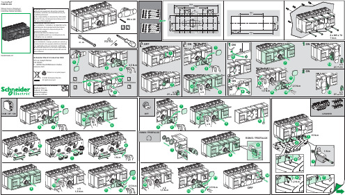
04445322A-07Manual source changeoverInverseur manuel monoblocTransfer PacTFXM100-250Schneider Electric Industries SAS35 rue Joseph MonierCS 30323F - 92506 Rueil Malmaison Cedex© 2022 Schneider Electric.All rights reserved.Printed on recycled paper.TENGA EN CUENTAp La instalación, manejo, puesta en servicio ymantenimiento de equipos eléctricos deberánser realizados sólo por personal cualificado.p Schneider Electric no se hace responsablede ninguna de las consecuencias del uso deeste material.REMARQUE IMPORTANTEp L’installation, l’utilisation, la réparation et lamaintenance des équipements électriquesdoivent être assurés uniquement par dupersonnel qualifié.p Schneider Electric décline touteresponsabilité quant aux conséquences del’utilisation de ce matériel.PLEASE NOTEp Electrical equipment should be installed,operated, serviced, and maintained only byqualified personnel.p No responsibility is assumed by SchneiderElectric for any consequences arising out ofthe use of this material.04445322A-07Transfer PacTFXM320-630Manual source changeoverInverseur manuel monoblocSchneider Electric Industries SAS35 rue Joseph MonierCS 30323F - 92506 Rueil Malmaison Cedex© 2022 Schneider Electric.All rights reserved.Printed on recycled paper.TENGA EN CUENTAp La instalación, manejo, puesta en servicio ymantenimiento de equipos eléctricos deberánser realizados sólo por personal cualificado.p Schneider Electric no se hace responsablede ninguna de las consecuencias del uso deeste material.REMARQUE IMPORTANTEp L’installation, l’utilisation, la réparation et lamaintenance des équipements électriquesdoivent être assurés uniquement par dupersonnel qualifié.p Schneider Electric décline touteresponsabilité quant aux conséquences del’utilisation de ce matériel.PLEASE NOTEp Electrical equipment should be installed,operated, serviced, and maintained only byqualified personnel.p No responsibility is assumed by SchneiderElectric for any consequences arising out ofthe use of this material.。
True Blue Power 9018558 电源转换器手册说明书

Revision K• June 8, 2022FOREWORDThis manual provides information intended for use by persons who, in accordance with current regulatory requirements, are qualified to install this equipment. If further information is required, please contact:True Blue Powerc/o Mid-Continent Instrument Co., Inc.Attn: Customer Service Dept.9400 E. 34th St. N. Wichita, KS 67226 USA Phone 316-630-0101 Fax 316-630-0723We welcome your comments concerning this manual. Although every effort has been made to keep it free of errors, some may occur. When reporting a specific problem, please describe it briefly and include the manual part number, the paragraph/figure/table number and the page number. Send your comments to:True Blue Powerc/o Mid-Continent Instrument Co., Inc.Attn: Technical Publications9400 E. 34th St. N. Wichita, KS 67226 USA Phone 316-630-0101 Fax 316-630-0723© Copyright 2016Mid-Continent Instrument Co., Inc.Download the current version of thisinstallation manual using yoursmartphone or tablet.TABLE OF CONTENTSSECTION 1 GENERAL DESCRIPTION 41.1 INTRODUCTION 4 1.2 TECHNICAL SPECIFICATIONS 5SECTION 2 PRE-INSTALLATION CONSIDERATIONS 62.1 COOLING 6 2.2 EQUIPMENT LOCATION 6 2.3 ROUTING OF CABLES 6 2.4 LIMITATIONS 6 2.5 MODIFICATION 7SECTION 3 INSTALLATION 83.1 GENERAL INFORMATION 8 3.2 UNPACKING AND INSPECTING EQUIPMENT 8 3.3 CABLE HARNESS 8 3.4 MOUNTING 11 3.5 INSTALLATION CAUTION 11 3.6 INSTALLATION COMPLETION 11 SECTION 4 OPERATION 124.1 ELECTRICAL PERFORMANCE 12 4.2 TC120AVILABLE CURRENT OVER THE OUTPUT VOLTAGE RANGE 12 4.3 PROTECTIVE FEATURES 13 SECTION 5 CONFORMANCE 155.1 INSTRUCTIONS FOR CONTINUED AIRWORTHINESS 15 5.2 ENVIRONMENTAL QUALIFICATION STATEMENT 15REVISION HISTORYRev Date Detail Approved A 02/10/2016 Initial release SHOB 03/04/2016 Updated EQF in Section 5, corrected input voltage range,added note to Section 2.4.BAWC 03/15/2016 Add -2 version.BAWD 05/27/2016 Updated wiring drawings in Section 3.VAAE 02/10/2016 Updated Section 4.2.1.KJWF 05/07/2020 Updated style and brand to meet Marketing and Engineering guidelines.DLRG 10/21/2020 Updated weight.MEKH 04/13/2021 Updated Section 4 – provided additional clarification in theoperation section; correct graph info; added new graph toillustrate power range.Section 5 corrected typoDLRJ 09/03/2021 Updated Sections 1.1, 1.2 and 5.2 to include MIL-STD testing WVCK 06/08/2022 Updated adjustable output range from 5-18VDC to 5-24VDCfor MOD 1 units. Updated Figures 4.1 and 4.2 accordingly.BAWSECTION 1 GENERAL DESCRIPTION1.1 INTRODUCTIONThe model TC120 DC/DC Power Converter is a lightweight power converter that translates a direct current (DC) input of 28 volts to an adjustable 5 to 24 volt direct current (DC) output.The input operating voltage (24–32VDC) makes the TC120 suitable for nearly any common general, business, or commercial aviation application and provides an adjustable DC output voltage of 5 to 24 VDC. The unit is rated for a nominal output of 120 watts to power avionics, instrumentation, personal charging, lighting, and many other applications. The TC120 DC/DC Converter is FAA certified to TSO-C71 and tested to rigorous environmental standards and levels of RTCA DO-160G, MIL-STD-810, MIL-STD-704 and MIL-STD-461. The small size and light weight in conjunction with its installation flexibility (inside or outside the pressure vessel) make it an ideal choice for aircraft power needs while reducing the challenges associated with other similar products.Highlighted features include short circuit protection, overload capability, low input voltage shut-down, temperature monitoring, reverse polarity protection, a self-resettable over-temperature disable and an optional remote enable (on/off) feature.The TC120 DC/DC converter has a robust Military-rated circular connector and a rugged aluminum case which dissipates heat and provides excellent mechanical strength. It is engineered to require no external cooling and contains no internal fans or cooling methods, which saves energy, reduces weight and allows more flexible installation locations. At only 11 ounces (312 g), it is lighter and smaller than any other certified solution in the aviation market today.1.2 TECHNICAL SPECIFICATIONSElectrical AttributesInput Voltage Rated 28VDC nominal, Operating 24 – 32VDC Input Current (full load) 5 amps max at nominal input voltageOutput Voltage 5 – 24 VDC adjustableOutput Power 120 watts nominalEfficiency 95% nominalTable 1.1Physical AttributesWeight 11.0 oz (312g)Dimensions(not including connector mate) 2.75 long x 3.75 wide x 1.29 high [inches] 69.9 long x 95.3 wide x 32.8 high [mm]Mating Connector Kit MCIA P/N 9018651Mounting Base mount – orientation not criticalTable 1.2QualificationsCertification FAA TSO-C71Environmental Qualification RTCA DO-160G,MIL-STD-461F, MIL-STD-704F & MIL-STD-810F; See Section 5.2Altitude -15,000 feet to +55,000 feet (65,000 feet non-operating)Temperature -55°C to +70°C (-67°F to +158°F)Table 1.3SECTION 2 PRE-INSTALLATION CONSIDERATIONS2.1 COOLINGThe TC120 product does not require external cooling or contain internal active cooling. Cooling of the unit occurs exclusively through passive conduction through the base or radiated cooling across the metal case. Additional cooling can be realized through convection (exposure to free moving air) or conduction (mounting to a thermally conductive metal surface). These methods are not required to achieve rated performance but can help prevent potential overheating and extend life when the unit is operated at full power or during overload conditions. Specifically, mounting the unit to a metal surface is preferred, but not required.2.2 EQUIPMENT LOCATIONThe TC120 is designed for mounting flexibility, allowing for installation inside or outside the pressure vessel with no requirement for temperature control. In addition to altitude and temperature resistance, the unit is also designed to withstand high levels of condensing humidity. However, installation locations where the unit could be subject to standing or direct water exposure should be avoided. The unit can be mounted in any orientation. Clearance should be provided for the mating connector and may require as much as five inches past the unit connector to allow for back shell access to the connector.2.3 ROUTING OF CABLESThe wires and cable bundle associated with the unit are heavy gauge wire and carry significant power. Be aware of routing cables near other electronics or with other wire bundles that may be susceptible to high energy flow.Avoid sharp bends in cabling and routing near aircraft control cables. Also avoid proximity and contact with aircraft structures, avionics equipment, or other obstructions that could chafe wires during flight and cause undesirable effects.2.4 LIMITATIONSThe conditions and tests for TSO approval of this article are minimum performance standards. Those installing this article, on or in a specific type or class of aircraft, must determine that the aircraft installation conditions are within the TSO standards. TSO articles must receive additional installation approval prior to being operated on each aircraft. The article may be installed only according to 14 CFR Part 43 or the applicable airworthiness requirements.2.5 MODIFICATIONThis product has a nameplate that identifies the manufacturer, part number, description,certification(s) and technical specifications of the unit. It also includes the “MOD” or modification number representing notable changes in the hardware design of the unit.Modification (MOD) 0 is the initial release of the product and is identified on the nameplate by the lack of marking on the MOD numbers 1 through 9 (i.e. 1-9 are visible). All subsequentmodifications are identified on the nameplate by the marking/blacking out of that particular MOD number (i.e. for MOD 1, the number 1 is not visible and 2-9 are visible - see Figure 2.1 forexamples). MODs do not have to be sequentially inclusive and may be applied independent of each other.MOD 1: Update adjustable output voltage range to 5 – 24 VDC. NOTE: Units prior to MOD 1 have an adjustable output voltage range of 5 – 18 VDC.For additional details regarding specific changes associated with each MOD status refer to the product published Service Bulletins at .Figure 2.1Nameplate and MOD Status ExampleMOD 0 MOD 1 MOD 1 & MOD 2SECTION 3 INSTALLATION3.1 GENERAL INFORMATIONThis section contains interconnect diagrams, mounting dimensions and other information pertaining to the installation of the TC120 DC/DC Converter. After installation of cabling and before installation of the equipment, ensure that power is applied only to the pins specified in the interconnect diagram.The following two versions of the unit are available. See section 4.2.1 for additional details of the remote enable (on/off) feature and installation details within section 3.Part Number Remote On/Off6430120-1No (output always enabled)6430120-2Yes (enable signal required)3.2 UNPACKING AND INSPECTING EQUIPMENTWhen unpacking this equipment, make a visual inspection for evidence of any damage that may have incurred during shipment. The following parts should be included:A. DC/DC Converter P/N 6430120-( )B. Connector Kit P/N 9018651i. Mating Connectorii. Strain ReliefC. Installation Manual P/N 9018558Equipment not provided:A. Mounting Hardware four 6-32 x 1” (min) pan head screws#6 lock washers (optional)B. Cable Harness Wire See Section 3.3 for specifications3.3 CABLE HARNESSConstruct the cable harness with regards to the instructions below, and using Figures 3.3 – 3.5, and Wiring Diagram of Table 3.3.Refer to Section 2: Pre-Installation Considerations in regards to routing precautions.3.3.1 Wire Gauge SelectionUse of PTFE, ETFE, TFE, Teflon, or Tefzel insulated wire is recommended for aircraft use.Use the following wire gauges for each of the pins in the connector:Pins A and B – 18 or 16 AWG stranded or solidPins C and D – 16 AWG stranded or solidPin E – 24 AWG stranded or solid3.3.2 Pin Assignment InformationDC Input – Connect pin A to the aircraft positive 28 VDC bus (24-32 VDC) (7.5 amp circuit breaker recommended)DC Return – Connect pin B to input power return or aircraft ground. Equivalent to pin D DC Output – Connect pin C as the positive output voltage (adjustable)DC Return – Connect pin D to output return or aircraft ground. Equivalent to pin B Enable – 6430120-1: pin E to remain open/unconnected 6430120-2: pin E to be grounded to enable power output (via switch or similar. See section 4.2.1 and figure 3.3 for related details)Figure 3.1Table 3.1Pinout View of Unit ConnectorConnector Pinout3.3.3 Harness VerificationWith the TC120 DC/DC Power Converter disconnected, activate the aircraft power bus that supplies the unit and use a multi-meter to measure and verify the power, ground, and enable voltages on the appropriate pins within the mating harness.3.3.4 Output Voltage AdjustmentThe output voltage can be set to any value between 5 and 24VDC.NOTE: The default output voltage is initially set to approximately 13.8V at the factory.The output voltage may be adjusted while the TC120 DC/DC Power Converter isconnected to the mating harness and aircraft power but disconnected from the output load. Use a multi-meter at the load end of the harness to measure output voltage.The adjustment trimmer can be accessed by removing the flat-head screw near the label as shown in Figure 3.4. After removing the screw, a flat blade screwdriver (2mm) will fit into the hole and the trimmer screw slot. Turn the trimmer carefully either clockwise to increase voltage or counter-clockwise to decrease voltage. Replace the flat-head screw after adjustment is complete.Connector Pinout A DC Input B DC Return C DC Output D DC Return EEnableADB E CFigure 3.2: Typical 6430120-1 Aircraft Wiring Installation – Constant OnFigure 3.3: Typical 6430120-2 Aircraft Wiring Installation – Remote On/Off3.4 MOUNTINGRefer to Section 2: Pre-Installation Considerations in regards to equipment location.The TC120 DC/DC Converter is designed for base mounting only. Four 6-32 mounting holes should be provided in the aircraft in accordance with Figure 3.6. Secure the unit with four 6-32 pan head screws, or equivalent. A lock washer under the head of each screw is recommended.Figure 3.4TC120 DC/DC Converter Outline Drawing3.5 INSTALLATION CAUTIONUnder no circumstances should the output of the Converter to be connected to another power output source or damage will occur to the unit or the connected power source.3.6 INSTALLATION COMPLETIONPrior to operating the unit in the aircraft, it is recommended to verify the output and functionality of the unit. In order to prevent accidental damage to other systems, it is best not to attach the output to other equipment or power busses prior to verification. Verify the output of the unit at the terminating end of the cable with a multi-meter to ensure proper voltage and polarity. Once verified, installation can be completed and functionality of the remote on/off feature (if used) should be checked.SECTION 4 OPERATION4.1 ELECTRICAL PERFORMANCEThe TC120 DC/DC Converter is designed as a high-efficiency non-isolated, buck topology, solid-state switch-mode power supply. The unit converts a DC voltage input to a user-selected regulated 5 to 24 VDC output. The Pulse-Width-Modulation (PWM) circuits utilize current-mode control technology. The current-mode control operates at high frequency and pulse-by-pulse protects the internal power devices from excessive current.4.2 TC120 AVILABLE CURRENT OVER THE OUTPUT VOLTAGE RANGEThe TC120 continuous rated output current, and thus power, is a function of the user-selected output voltage. If the selected output voltage is lower than 9 VDC, total power output is limited by individual component ratings, including the connector pins. See Figure 4.1 for maximum continuous and temporary output current for a given output voltage.The left side of Figure 4.1 shows the continuous current region of the TC120 (in blue). The area to the right of the Power Limit line shows the temporary current capability of the TC120 (in red). The continuous rated current can be exceeded for short periods of time in this region to accommodate surge conditions and fault conditions. This also allows the TC120 the capability to trip slow-acting thermal circuit breakers under fault and short-circuit conditions without degradation.For minimum voltage drop at the load and for best thermal conduction, use of the largest wire size possible is recommended (i.e. 16 AWG).Figure 4.1TC120 Continuous and Temporary Output Current Limits and Output Voltage4.3 PROTECTIVE FEATURES4.3.1 Input Voltage RangeThe specified operating range of the input voltage for the TC120 is 22 to 34 VDC. However, the TC120 can temporarily operate at much lower voltages for start-up and emergencyconditions. See Figure 4.2The Temporary Operating Range (in yellow) represents a voltage range where extensiveperformance and qualification measurements have not been made other than for DO-160 Section 16 for low voltage input down to 18VDC. To request more detailed characterization for operation and behavior below input voltage of 22 VDC, contact True Blue Power.4.3.2 Maximum Input VoltageIf the input voltage to the TC120 exceeds 34VDC, the unit senses an over-voltage at theinput and disables the output. The TC120 resumes normal operation when the inputvoltage drops below 34VDC.4.3.3 Output Voltage RangeThe specified operating range of the output voltage for the TC120 is adjustable between 5 and 24 VDC. Each individual TC120 is tested to this range. The output can be adjusted per the procedure in section 3.3.4 above. If you require an adjustment range other than thespecified 5 to 24 VDC range, contact True Blue Power.As shown in Figure 4.2, within the specified output voltage range, the unit can only supply a maximum of approximately one volt (1 VDC) below the input voltage. As an example, if the output voltage is set for 18 Volts and the input voltage falls below 19 Volts, the outputvoltage will begin to fall as well at approximately 1 Volt less than the input voltage.Figure 4.2TC120 Input Voltage vs Output Voltage Range4.3.4 Remote On/OffA version of the TC120 DC/DC Converter (6430120-2) incorporates a remote ON/OFF feature that allows the user to enable or disable the output of the unit remotely. By providing a ground to the appropriate pin, the user can enable the output of the unit via a remote mounted switch. (See Figure 3.3)4.3.5 Over-TemperatureThe TC120 DC/DC converter uses a high-efficiency conversion process. The TC120 at maximum continuous power will have a case temperature typically 20C over ambient. For additional protection the TC120 has an internal temperature sense device that continually provides monitoring and feedback to the control circuits. When the unit senses an internal condition that exceeds maximum temperature ratings the output is disabled. The converter will continue to remain shut-down until the temperature returns to within acceptable limits. This over temperature reset occurs automatically without external intervention required. 4.3.6 Short CircuitThe TC120 DC/DC converter has a maximum output current. As the load current increases beyond the maximum continuous rating a point will be reached where the TC120 output voltage begins to drop. At a full short-circuit the input current to the TC120 is low but the output current is approximately 22.5 Amps (See Figure 4.1). The TC120 can withstand continuous short-circuit operation without damage.If it is undesirable in your installation for the wiring to be subjected to high currents in a short-circuit fault condition a circuit breaker on the TC120 output should be used.SECTION 5 CONFORMANCE5.1 INSTRUCTIONS FOR CONTINUED AIRWORTHINESSNo periodic scheduled maintenance or calibration is necessary for continued airworthiness of the TC120 DC/DC Converter. If the unit fails to perform to specifications, the unit must be removed and serviced by Mid-Continent Instruments and Avionics or their authorized designee.5.2 ENVIRONMENTAL QUALIFICATION STATEMENTMODEL NUMBER: TC120 PART NUMBER: 6430120-( ) DESCRIPTION: DC/DC Converter CERTIFICATION: FAA TSO-C71 MANUFACTURER: True Blue Power, a division of Mid-Continent Instrument Co., Inc. ADDRESS: 9400 E. 34th St. North, Wichita, KS 67226, USA.SPECIFICATION: Test Specification (TS) 627 Test Data Sheet (TDS) 627 STANDARDS: RTCA DO-160, Rev G, dated 12/08/10; MIL-STD-461F, dated 12/10/07MIL-STD-704F, dated 03/12/04, MIL-STD-810F, dated 01/01/00DESCRIPTION OF TEST SECTION CATEGORY Temperature and Altitude 4 Category F21 Temperature Variation 5 Category S2 Humidity 6 Category B Operational Shock and Crash Safety 7 Category B1Vibration 8 Fixed Wing: Category R; Curve C, C1 Rotorcraft: Category U, Curve GExplosion 9 Category X Waterproofness 10 Category X Fluids 11 Category F2 Sand and Dust 12 Category D Fungus 13 Category FSalt Fog 14 Category S Magnetic Effect 15 Category Z Power Input 16 Category B(XX)3 Voltage Spike 17 Category A Audio Frequency Conducted Susceptibility 18 Category R4 Induced Signal Susceptibility 19 Category X4 Radio Frequency Susceptibility 20 Category X4 Emission of Radio Frequency Energy 21 Category M4 Lightning Induced Transient Susceptibility 22 Category XXH2L2 Lightning Direct Effects 23 Category XIcing 24 Category XESD 25 Category A Fire, Flammability 26 Category XREMARKS:1 - Qualified to MIL-STD-810F (500.4, 501.4, 502.4, 516.5)2 - Fluids: Deicing Fluid, Solvent (IPA), Cleaning Fluid3 - Qualified to MIL-STD-704F/MIL-HDBK-704-8 (LDC101 – LDC602)4 - Qualified to MIL-STD-461F (CE102, RE102, CS101, CS114, CS115, CS116, RS103)。
艾东(Eaton)Magnum自动转换器交换器说明书
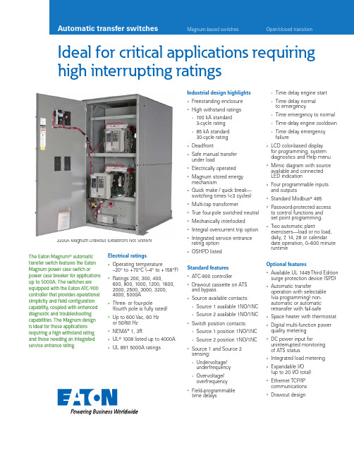
Ideal for critical applications requiring high interrupting ratingsThe Eaton Magnumா automatic transfer switch features the Eaton Magnum power case switch or power case breaker for applications up to 5000A. The switches are equipped with the Eaton ATC-900 controller that provides operational simplicity and field configuration capability, coupled with enhanced diagnostic and troubleshooting capabilities. The Magnum design is ideal for those applications requiring a high withstand rating and those needing an integrated service entrance rating.Electrical ratings• Operating temperature–20° to +70°C (–4° to +158°F)• Ratings 200, 300, 400, 600, 800, 1000, 1200, 1600, 2000, 2500, 3000, 3200, 4000, 5000A• Three- or four-pole(fourth pole is fully rated)• Up to 600 Vac, 60 Hzor 50/60 Hz• NEMA® 1, 3R• UL® 1008 listed up to 4000A • UL 891 5000A ratings3200A Magnum Drawout (Deadfront Not Shown)Industrial design highlights• Freestanding enclosure• High withstand ratings• 100 kA standard3-cycle rating• 85 kA standard30-cycle rating• Deadfront• Safe manual transferunder load• Electrically operated• Magnum stored energymechanism• Quick make / quick break—switching times (<3 cycles)• Multi-tap transformer• True four-pole switched neutral• Mechanically interlocked• Integral overcurrent trip option• Integrated service entrancerating option• OSHPD listedStandard features• ATC-900 controller• Drawout cassette on ATSand bypass• Source available contacts:• Source 1 available 1NO/1NC• Source 2 available 1NO/1NC• Switch position contacts:• Source 1 position 1NO/1NC• Source 2 position 1NO/1NC• Source 1 and Source 2sensing:• Undervoltage/underfrequency• Overvoltage/overfrequency• Field-programmabletime delays• Time delay engine start• Time delay normalto emergency• Time emergency to normal• Time delay engine cooldown• Time delay emergencyfailure• LCD color-based displayfor programming, systemdiagnostics and Help menu• Mimic diagram with sourceavailable and connectedLED indication• Four programmable inputsand outputs• Standard Modbus® 485• Password-protected accessto control functions andset point programming.• Two automatic plantexercisers—load or no load,daily, 7, 14, 28 or calendardate operation, 0–600 minuteruntimeOptional features• Available UL 1449 Third Editionsurge protection device (SPD)• Automatic transferoperation with selectable(via programming) non-automatic or automaticretransfer with fail-safe• Space heater with thermostat• Digital multi-function powerquality metering• DC power input foruninterrupted monitoringof ATS status• Integrated load metering• Expandable I/O(up to 20 I/O total)• Ethernet TCP/IPcommunications• Drawout designContact Wear IndicationDrawout Power Case Switch or Breaker is OptionalKeyed Switch for Service Entrance OptionSource 1Source 2Multi-Tap TransformerMagnum 2000A Drawout with Service EntranceFixed mounted and drawout capabilityThe standard Magnum design up to 3200A comes with a fixed mounted design withSource 1 at the top and Source 2 at the bottom. On the 4000A and 5000A ratings, the design comes only as a drawout design. Drawout design is available on all units. Optionally, the Source 1 /Source 2 can be reversed to have Source 1 on the bottom. Selective coordination The Magnum switch is ideal for emergency, legally required standby systems or other critical operations requiring selective coordination. Magnum bypass switches up to 4000A are UL 1008 listed for 85 kA withstand rating for 30 cycles on units up to 4000A. Fast transfer timeThe Magnum transfer switch uses a high-speed transfer mechanism that allows open in-phase transfer on large ratings. This feature is factory selectable to be an openin-phase transfer with a default to load voltage decay or a default to time delay neutral. The Magnum comes standard with a delayed transition.Integrated service entrance ratingThe factory addition of anoptional overcurrent trip to the power case switch enables the bypass unit to be rated as a service entrance bypass isolation ATS. Selection of the overcurrent trip can be made from the series of Eaton Digitrip™ RMS trip units including the standard Digitrip 520 or optional 520M, 520MC or 1150.Arcfl ash Reduction Maintenance System™The switch can be supplied with the optional ArcflashReduction Maintenance System maintenance mode function with the selection of the Digitrip RMS 520MC or 1150 trip units. This feature will reduce arc flash incident energy that is generated on a fault condition.Multi-tap voltage selector Allows the transfer switch to be readily applied on most system voltages worldwide by connecting to the proper terminals. Available system voltages include 120, 208, 220, 230, 240, 380, 401, 415, 480 or 600 Vac, 50 or 60 Hz.Contact wear indication All Magnum switches include a contact wear indicator. The contact wear indicator is viewed by removing the arc chutes and shows if the contacts are good or if there is wear indicated.ATC-900 controllerEaton’s new ATC-900 controller brings ease of use, adaptability, supervisory and programming capabilities to mission-critical applications. The 4.3-inch color TFT display provides simple arrow keys for quick screen navigation. Event logging and recording of time-stamped events are viewed easily. Field configuration of I/O allows user adaptability to special requirements.ATC-900 ControllerDeadfront2EATON Automatic transfer switchesMagnum transfer switches 200–3200A(Controller and Device Panels Mounted on Inner Door)Magnum 4000–5000A UnitsA Seismic mounting brace adds an additional 3 inches to each side—front left and front right sideand 3 inches additional to rear side.3EATON Automatic transfer switchesEaton is a registered trademark.All other trademarks are property of their respective owners.Eaton1000 Eaton Boulevard Cleveland, OH 44122United States © 2014 EatonAll Rights Reserved Printed in USAPublication No. PA140002EN / Z14844March 2014Automatic Magnum-Based T ransfer Switch Catalog Numbering SystemSystem Coordination Information—A Ratings used for coordination with upstream breakers with short-time ratings.B UL 1066 short-time withstand rating.Fully rated fourth pole (switched neutral)Eaton provides a fully rated switched neutral or fourth pole, meaning that the fourth pole has withstand, interrupt and closing ratings identical to the power contacts. The neutral pole is operated on a common shaft with the power contacts, thereby ensuring simultaneous opening and closing of the switched neutral. Eaton’s fully rated fourth pole eliminates typical problems with a three-pole overlapping neutral:•Eliminates nuisance ground trips at the main due to circulating zero sequence harmonic current between sources•Reduction in ground current due to isolated single ground point lowers arc-flash levels and reduces generator damage•Eliminates potential for faults to propagate across overlapping neutral; fully rated fourth pole will handle as a normal operation •Does not generate voltages that exceed normal phase voltageotee:N For more detail, reference Eaton white paper Three- and Four-Pole Transfer Switching Characteristics , IA08700002E.A Drawout design only.otee:N PCS = power case switch PCB = power circuit breaker。
FT 120 中文操作手册
MilkoScan FT-120乳品分析仪中文操作手册北京福斯杰科技有限公司F os s C hi na Se r vi c e Ce n te r目录第1章简介 (6)§1。
1FT—120乳品分析仪 (6)§1。
2关于这本手册 (6)§1.3福斯电子的校准模块 (7)§1。
4FT—120仪器可选择的模块 (7)§1。
4。
1自动清洗和调零模块(ACZ) (7)§1。
4。
2 应用模块 (7)§1。
4。
3 天平选项 (7)§1。
4。
4 高级性能模块 (8)§1。
4. 5高级校准模块 (8)§1. 4. 6 输入选择模块 (8)§1。
4。
7 数据交换选择模块(DDE) (8)§1。
4.8 品质确认模块 (8)§1.5窗口系统 (9)§1. 5. 1 菜单栏 (9)§1。
5。
2 功能键 (10)§1。
5。
3 按钮栏 (10)§1。
5。
4 滚动栏 (10)§1. 5。
5 状态栏 (10)§1。
6定义自己的窗口 (10)§1。
7仪器语言支持 (10)§1. 7。
1 怎样使用当地语言 (11)§1。
8激光的保险装置 (11)第2章FT—120乳品分析仪用户界面 (11)§2。
1FT—120乳品分析仪插图屏幕说明 (12)§2。
2按钮板 (13)§2。
3功能键 (13)§2.4快捷键 (14)§2.5其它菜单 (14)§2。
6菜单概要 (15)§2。
6。
1 菜单中的基本模块 (15)§2。
6。
2 应用模块菜单 (16)§2.7物理连接与转换 (17)第3章操作 (18)§3。
1调零和实验样品 (18)§3. 1。
蓝马A1+产品手册
1.产品特性• 完全支持CAN总线V2.0A和V2.0B技术规范:- 0 - 8 字节报文长度- 标准数据帧、扩展数据帧、远程帧- 可软件选择位传输速率20K~1 Mb/s- 可软件设置屏蔽滤波功能• 使用配套的调试软件,进行CAN总线数据收发,实现CAN总线调试。
- 简化CAN应用- 可实时观察,监测CAN总线数据- 可定时发送数据,方便调试- 可应答方式发送数据,模拟从机调试• 硬件特性:- USB虚拟串口- 带有可选择使能设定的中断输出引脚- 工作电压:直流5V,USB接口供电,无需外接电源。
- 40 mA 典型工作电流- 50 mA 最大工作电流•工业级温度标准:-40ºC ~ +85ºC2.转换器介绍USB-CAN-A1+转换器,为A1型转换器升级版本,一路USB接口和一路CAN接口,可作为一个标准CAN节点,通过PC连接到CAN网络,实现工控现场CAN总线数据的收、发双向传输。
广泛应用于工业控制、安防监控、智能建筑、汽车电子等领域。
增加动态链接库,可以进行二次开发。
转换器体积小,无需外接电源,便于携带,尤其适合在笔记本电脑上应用,连接到CAN总线现场,进行数据采集,处理,调试等。
2.1 转换器图片2.2 信号接口1、USB接口:USB-A插头2、CAN接口:2P蓝色欧式接线端子,参看1.1图片,CAN_H、CAN_L为CAN总线接口。
3、跳线JP1-CAN总线120欧终端电阻:跳线短接,电阻接入,跳线断开,电阻断开。
3.驱动安装3.1 打开驱动在光盘USBdriver目录中,找到并运行安装文件。
3.2 运行安装运行到下图,选择上 launch the CP210X VCP Driver Installer.前面的勾。
3.3 选择安装目录安装到默认目录,点Install.3.4 安装完成安装完驱动后插入转换器,设备管理器中会找到USB设备。
(COM3)4.通讯调试本转换器必需使用配套CAN总线调试软件(4.x版本)进行通信调试,详细过程如下:4.1 连接转换器CAN接口连接到总线、将转换器插入PC机USB接口,即可进入调试。
AIMS Power纯正波电源电压转换器说明书
DC TO AC PURE SINE POWER INVERTERPWRI200012120SINSTRUCTION MANUALETL Listed to UL 458 and CSA 22.2 NO 107.1INTRODUCTIONThe AIMS Power pure sine inverter product line is used for back-up or mobile power. The pure sine product line is ideal for sensitive equipment and provides clean power, which is more efficient for back-up power applications. The power inverter transforms DC (direct current) electricity into AC (alternating current) power that can be used for running a wide variety of medium size devices up to 16 amps, using a battery. This inverter is perfect for providing mobile power in vehicles, RVs, boats, vans or buses.Read this instruction manual carefully and make sure your inverter is installed properly before using.WARNING AND SAFETY1.Keep manual for future reference.2.Do not put the inverter under direct sunlight or near a heating source.3.The case of the inverter will get hot when used. Do not allow flammablematerials to contact the inverter, such as clothing, sleeping bags, carpet or any other flammable materials. The heat from the inverter can damage these items.4.The power inverter is designed to be used with a negative ground electricalsystem! Don't use with positive ground electrical systems (the majority of modern automobiles, RVs, trucks and boats are negative ground).5.Do not disassemble the unit: it may cause fire or electric shock.6.This device should only be serviced by a qualified technician. This item does nothave any serviceable parts.7.Prevent body contact with grounded surfaces such as pipes, radiators, ranges,and refrigerator enclosures during installation.8.Do not operate the inverter if under the influence of alcohol or drugs. Readwarning labels on prescriptions to determine if your judgment or reflexes are impaired while taking drugs. If there is any doubt, do not operate the inverter. 9.People with pacemakers should consult their physician(s) before using thisproduct. Electromagnetic fields in close proximity to a pacemaker could cause interference to or failure of the pacemaker.10.Keep the inverter well-ventilated. Do not place any objects on top of or next tothe inverter or allow anything to cover the cooling fans; doing so can cause the inverter to overheat, causing a potential fire hazard and/or damage to theinverter. Leave adequate ventilation space underneath the inverter as well; thick carpets or rugs can obstruct air flow, causing the inverter to overheat.11.Avoid unintentional starting. Be sure the switch is in the OFF position when not inuse and before plugging in any appliance.12.Keep inverter away from children. Don't install the inverter where it is accessibleto children.13. The power inverter will output the same AC power as utility power, please treatthe AC outlets as carefully as you would your home AC outlets. Do not put anything other than an electrical appliance into the output terminal. It may cause shock or fire.14.Disconnect the battery and inverter when not in use.Note: Performance of this unit may vary depending on the available battery power or appliance wattage.Warning: The warnings, cautions, and instructions discussed in this instruction manual cannot cover all possible conditions and situations that may occur. It must be understood by the operator that common sense and caution are factors which cannot be built into this product, but must be supplied by operator. Guard against electric shock. Do not open the metal case; risk of electric shock.INVERTER FEATURES•Dual GCFI outlet•USB Port•LED protect indicator•LED power indicator•Easy push on/off switch•Remote port for on/off remote switch (optional)•Thermally controlled cooling fan•Low battery voltage warning/shutdown•High input voltage protection with automaticshutdown•Over load indicator•Short circuit protection•AC output short circuit protectionINSTALLATIONEnsure there is enough space for the installation, and the location should be meet the following requirements:1.Water should not access the inverter.2.The ambient temperature should be 32~104°F, and the preferred temperature is50-77°F. The lower the better in this range of ambient temperature.3.Do not mount the inverter upside down.4.We recommend mounting the inverter on something stable to prevent it frombouncing. Impact shock could result in damage to your unit. Be sure to use all four mounting screws for optimal stability. Mount in a location that can support the weight of the inverter.5.Allow 12 inches of space around the inverter to prevent objects from blockingthe vents and to provide enough air to circulate.6.Do not place objects that will block the vents. Allow enough air to circulate.7.Do not install the inverter in an environment with high dust, saw dust residue orother particles that may get sucked into the inverter increasing internaltemperature.8.There will be some electrical arcing or spark when the inverter connects with thebattery. Combustible materials such as gasoline, alcohol, etc. should not bearound the inverter.BATTERY1.The battery is designed to supply the inverter with DC input voltage and the ratedvoltage should be in accordance with the rated input voltage of the inverter. Any voltage exceeding the range of the input voltage of the inverter will cause the inverter to go into overload and could possibly damage the inverter. The battery should supply enough current for the load. The load is the amp or watt rating of the equipment being powered by the inverter. A small capacity battery cannot provide enough power for large electrical equipment. In this case, the battery will cause the inverter to go into under voltage protection because of the load put on the battery. A simple way to calculate the load or amps required from your battery is to divide watts of equipment by battery voltage. Due to the consumption of the inverter itself, the actual current will be about 10%more. For example, the voltage of lead acid battery is 12VDC, and load of the equipment is 1000W,therefore, the actual current needed from the battery is about 1000W / 12V = 83.3amps per hour. Add 10% for efficiency loss and you get 83.3 * 1.10% = 91.6 amp per hour needed. If you don’t know the wattage of your equipment, you can figure thewattage by multiplying AC amps by AC voltage. For example, a refrigerator is8 AC amps * 120 Volts AC = 960 watts. Remember, all equipment has a start-up requirement 3-5x its running wattage. In this example, 960 watts * 3 = 2880 watts needed from the inverter so don’t size your inverter too small.2.Battery operating time depends on battery capacity and load. The formula foroperating time is: battery capacity divided by the value of the load divided bybattery voltage times 1.10%. For example, using the numbers from above, the battery specification is 12V, 200Ah capacity and the load is 1000W. Take battery capacity 200Ah / 91.6 amps = 2.18 hours of run time if you fully deplete thebattery. This is NOT recommended. Deep cycle batteries last longer when they are only depleted to 50% of capacity.CONNECTION1.GroundingThe power inverter has a terminal on the rear panel marked " Grounding "or "≡".This is used to connect the chassis of the power inverter to ground. The ground terminal has already been connected to the ground wire of the AC outputreceptacle through the inverter.The ground terminal must be connected to the ground wire, which will varydepending on where the power inverter is installed. In a vehicle, connect theground terminal to the chassis of the vehicle. In a boat, connect it to the boat’s ground system. In a fixed location, connect the ground terminal to earth.2.Battery terminalsBefore you connect the battery cables, make sure the power switch is in the off position. Connect Red (+) battery cable to Red (+) inverter terminal. Connect Black (-) battery cable to Black (-) inverter terminal. Connect Red (+) batterycable to Red (+) battery terminal. Connect Black (-) battery cable to Black (-)battery terminal. Alligator clamp cables may be used but only to connect to the battery. Do not use clamps on inverter terminals. Alligator clamps are not apermanent solution. You may see a spark during connection. Do not reverse the polarity. This may damage the inverter and void warranty.3.If connecting to a breaker panel do NOT neutral ground bond the panel.USING THE POWER INVERTER1.Check the output voltage and capacity of the battery. The battery (s) shouldmatch the voltage of the inverter and have enough capacity for the load.2.Connect your inverter to your battery bank and do not to reverse the polarities ofthe connection.3.Press the power switch button on your inverter for .5 seconds and a green LEDwill light up indicating that the inverter is on.4.Before plugging anything into your inverter, make sure the appliance you aretrying to power is shut OFF, then plug it into the AC outlet of your inverter and power on your appliance.5.Once finished using the inverter, turn off your electrical appliance and theinverter. The indicator lights should be off.6.The cooling fans inside the inverter do not work until the case temperaturereaches approximately 104°F.7.If you do not plan to use the inverter for a long period of time, disconnect it fromyour battery bank. Leaving the inverter on and connected for long periods oftime may harm the equipment and over discharge the battery.SOFT START TECHNOLOGYThe soft start technology built into this inverter protects the unit from delivering too much AC power at once by gradually increasing the AC voltage pushed out.To make sure that you are utilizing this feature, turn on the appliance being used before turning on the inverter. This is especially necessary for equipment that has an inductive load or electrical motor.OUTPUT VOLTAGE & WAVEFORMThe electrical waveform output of this inverter is a pure sine wave, which has the same quality as utility and/or domestic power. This type of waveform is suitable for most electrical devices, appliances and tools. This pure sine wave unit provides more capabilities than modified sine wave inverters because it is a cleaner form of power. The pure sine wave also effectively reduces the noise produced while using appliances.PROTECTIONS IN THE INVERTER1.Input under-voltage alarm: When the input DC voltage is lower than 9.8V(19.6V/39.2V), the buzzer will whistle intermittently to remind that the inverterwill go into the under voltage protection.2.Under voltage protection: The inverter will automatically shut down when theinput DC voltage is lower than 9.5V(19V/38V). The buzzer will whistlecontinuously and the green light is off, red light is on. Please turn off theinverter and use it after recharging the battery.3.Over voltage protection: The inverter will automatically shut down when theinput DC voltage is higher than 16V(32V/62V). The buzzer will whistlecontinuously and the green light is off, red light is on. Please turn off theinverter and adjust the input voltage to the admissible range.4.Overload protection: The inverter will automatically shut down when the load ishigher than the rated power. The buzzer will whistle continuously. Turn off the inverter and resume to normal operation after taking away the excessive load.5.Short-circuit protection: The AC output will automatically shut down when shortcircuited. It will automatically reset after the problem is solved.6.Thermal protection: The unit will get hot during operation. If the temperature ishigher than 149°F, the inverter will automatically shut down. Then the buzzer will whistle continuously and the green light is off, red light is on. Please turn off the inverter, and continue using it after the temperature goes back tonormal naturally. Meanwhile find out the factors causing the fault, such asventilation, ambient temperature, vent, load power etc. It can avoid similarthings from happening again.**NOTE** The numbers in the parenthesis are for 24V and 48V models. In the case of over voltage, under voltage and thermal protection, the inverter will shut down. When the inverter is in the OFF position, the inverter doesn't consume battery current.HI-POT TESTING OF DC to AC InverterMost of our AC inverters are Listed by Intertek to conform to UL 458 standards. One of the requirements of UL 458 is that all AC inverters pass a High Voltage Dielectric Withstand Test, commonly called the Hi-Pot Test. The voltage applied to the control is usually equal to 1,000 volts, plus two times the line voltage rating of the inverter. Therefore, the standard hi-pot voltage for 115 VAC inverter is 1,250 VAC. For 230 VAC or dual voltage inverters, the hi-pot voltage is 1,500 VAC. This AIMS Power inverter is hi-pot tested before it leaves the factory, with a UL Certified hi-pot tester, set to the voltages shown above.(CAN/CSA-C22.2 No. 107.1) and are identified with the cETL Listed Mark.TROUBLESHOOTING TIPSFault / Display Cause SolutionsNo output voltage, buzzer sounds continuously Low input DC voltage Recharge or replace the batteryDo not use it when the battery is charging.Check the rated voltage of the battery andmake sure it is in within the range of the inputvoltage.High input DC voltageOverload Reduce the load power.Over temperatureRestart inverter after it resumes to normaltemperature. If t he load is too large,reduce the total load to the range of ratedpower. Avoid blocking the vent andimprove ventilation. Reduce the ambienttemperature.No output voltage The switch is off Turn on the power switch.Poor cable connection Check the cables and make sure they aretightly connected.GFCI has tripped.Check outlet and reset GFCI. If GFCIcontinues to trip, your load may be too large.You could also have a bad wire or there ismoisture. Check all wires, inverter and battery.Incorrect output voltage RMS Multimeter measurement error Use a true RMS multimeter to measure, suchas model FLUKE 177/179.The battery power ofRMS Multimeter is low.Try to maintain the input voltage in the rangeof rated power. The input voltage is toohigh or too low.Change the battery of the multimeter then testagain.Cannot drive the load Load is too large, or the actualpower of the applianceexceeds nominal power.Reduce the load or turn on the appliance first,then turn on the inverter.The starting power is larger thanrated power (such as motor).The internal soft-start circuit will buffer startingthe appliance.SPECIFICATIONSThe following situations will void warranty:1.The box is distorted, damaged or changed, and interior parts damaged because of an exterior hit or drop not reported at time of delivery.2.Connect the DC power incorrectly reversing the polarity.3.Dismantled or repaired the unit by an unauthorized person .4.The unit was damaged by incorrect installation or operating method .For additional products, please visit our web site: -Modified sine wave inverters-Pure sine wave inverters-Low Frequency Inverters-Solar Charge Controllers-Inverter Chargers-Converters DC-DC-Custom cut cables-Batteries-Solar Panels & RacksWARRANTYThis product is designed using the most modern digital technology and under very strict quality control and testing guidelines. If, however, you feel this product is not performing as it should, please contactus:************************ or (775)359-6703.We will do our best to resolve your concerns. If the product needs repair or replacement, make sure to keep your receipt/invoice, as that will need to be sent back along with the package and RMA# prepaid to AIMS. You have a full 2 year warranty from date of purchase.This warranty is valid worldwide with the exception that freight and duty charges incurred outside the contiguous 48 United States will be prepaid by customer.Except as noted above, AIMS makes no warranty of any kind, express or implied, including without limitation the implied warranties of merchantability and fitness for a particular purpose. In no event shall AIMS be liable for indirect, special or consequential damages. This warranty only applies to AIMS Power branded products. All other name brand products are warranted by and according to their respective manufacturer. Please do not attempt to return non-AIMS Power branded products to AIMS Power.04/21。
- 1、下载文档前请自行甄别文档内容的完整性,平台不提供额外的编辑、内容补充、找答案等附加服务。
- 2、"仅部分预览"的文档,不可在线预览部分如存在完整性等问题,可反馈申请退款(可完整预览的文档不适用该条件!)。
- 3、如文档侵犯您的权益,请联系客服反馈,我们会尽快为您处理(人工客服工作时间:9:00-18:30)。
默认ID:透传方式四、五发送数据时,使用此ID码。其它方式无效。
4.3.2.
CAN波特率选择。20K-1000K,多个波特率值可选。
屏蔽滤波:选中屏蔽滤波功能,在屏蔽和滤波寄存器内填入ID码即可实现屏蔽滤波功能
标准数据帧,填入2字节ID码。扩展数据帧,填入4个字节ID码。
通道:通道1或通道2,本型号只有通道1。
方向:数据传转输的方向。(发送或接收)
帧类型:标准数据帧、扩展数据帧、标准远程帧、护展远程帧
时间: 从MCU定时器,直接采样的精确时间。采样时点就是接收成功(或发送成功)后的时点。平均误差为20微秒。时间功能对于计算帧与帧之间的时间间隔很有意义。
图3-3 数据接收
接收扩展帧需填写四个字节,可以接收符合条件的扩展帧,此时不能接收标准帧。
接收条件:只有接收帧的ID与滤波寄存器的值相同时,此帧数据才可以收到,否则忽略。有时不需要所有的位都参加比较,可以设置屏蔽寄存器对ID中的哪些位进行滤波。如果某屏蔽位设置为零,对应的标识符位将被自动接收而不进行滤波。例如下图:屏蔽寄存器只有第一个字节高位是1其他位都是0,当收到ID第一个字节高4位与滤波寄存器的高4位相同时可以接收,否则数据被忽略。ID是53 80可以收到, ID是73 80 收不到(都是5)。
3.2.
打开CAN总线调试软件(4.9或更高版本),选择转换器参数,点击【连接设备】即可。软件操作如下图所示:
图3-1 软件操作图
3.3.
3.4.
选择设备型号为485/422-CAN F2,选择端口COM1(或其他端口),选择CAN通道1参数,然后点击【连接设备】按钮即可。
所有参数需要连接之前选定。如调试中需更改CAN参数,需释放设备并重新连接即可。
此方式只能透传标准数据帧,其他帧类型将被CAN模块丢弃。
5.3.
工作方式
数据长度
命令字及含义
帧构成
工作方式3
带ID的扩展数据帧
不定长度
带ID的扩展数据帧
(其他桢类型丢弃)
4字节ID识别码+1~8字节数据
8字节
带ID的扩展数据帧
(其他桢类型丢弃)
4字节ID识别码+8字节数据
例如串口发送数据到转换器:扩展数据帧(5字节)
ID码数据流
0x00 0x00 0x00 0x00 0xA1+0xA2+0xA3+0xA4+0xA5
此方式只能透传扩展数据帧,其他帧类型将被CAN模块丢弃。
5.4.
工作
方式
数据长度
命令字及含义
帧构成
工作方式4
不带ID的标准数据帧
不定长度
不带ID的标准数据帧
(其他桢类型丢弃)
1~8字节数据
8字节
不带ID的标准数据帧
五种透传方式可选:带命令头的透传、带ID的标准数据帧、带ID的扩展数据帧、不带ID的标准数据帧、 不带ID的扩展数据帧。详细介绍参考第4节《模块工作方式及通讯协议介绍》。
三种ID排列方式:MCP2510/2515、SJA1000、右对齐。详细参考 附录1。
数据帧固定长度8字节:如选中,发送数据必须满8字节,否则丢弃。接收时,自动补齐8个字节,空位填入FF.
OFF位置,转换器进入透传模式。
3.
转换器有调试模式和透传模式,在调试模式下,可以使用CAN总线调试软件(4.x版本)进行通信调试,还可以设置转换器参数参数。本章节详细介绍使用调试软件进行数据通讯过程。(注意:必须设置JP3 到ON,然后给转换器通电)
3.1.
JP3置为ON,CAN接口连接到总线、将F2转换器的485/422接口通过485转换器连上电脑,即可进入调试模式。
定时:固定时间间隔,自动发送数据,间隔时间可以设置,单位毫秒(MS)。
应答:接收到数据,自动应答一帧,将本栏数据发出,可模拟从机设备调试。
注:只有前8个字节的数据是有效的,超过8个会被忽略。
ID码说明:标准数据帧和标准远程帧,应填入2个字节。
扩展数据帧和扩展远程帧,应填入4个字节。
3.4.2.
表格方式显示接收数据。显示通道,数据收发方向,数据类型,ID码,数据内容等参数。
图3-8 显示设置
3.4.7.
环回模式:自发自收的模式,用于设备自我检测。
监听模式:只收不发的模式,监听重要总线时更安全。
图3-9 环回模式和监听模式
3.5.
转换器升级型号485/422-CAN F2支持二次开发,提供DLL动态链接库接口以及VC、VB、C#、JAVA、C++Builder、DELPHI的调用例程。详细开发介绍请参考
《USB-CAN A1 A2 dll接口函数包使用手册》
4.
转换器有调试模式和透传模式。在透传模式下,CAN数据不需要通讯协议,PC机向虚拟串口发送的数据,B2转换器直接向CAN总线发出,反之CAN总线上的数据也直接发到虚拟串口。用户只需关注数据,而不必关注通讯总线的转换过程。
4.1.
设置透传模式的工作参数需要进入调试模式,使用调式工具软件设置。
图3-4 ID选择方式方
还可以利用它,计算另一种排列方式的值。如上图5A 80 和 02 D4 其实是一样的。
3.4.4.
在连接设备之前选定使用屏蔽滤波功能,可以只接收符合条件的帧。不符合条件的帧都被忽略。改变屏蔽滤波设置需要重新连接设备。接收标准帧需填写两个字节,可以接收符合条件的标准帧,此时不能接收扩展帧。
-内置收、发缓冲器,一定限度防止数据丢失
硬件特性:
-标准485/422接口,波特率最高可达115.2Kbps。
- 总线采用光耦隔离,有效保护CAN总线通讯
- 电源采用DC-DC隔离模块,增强产品稳定性和可靠性
- 静电防护采用双向陶瓷气体放电管,设计总线接触放电6000V 空气放电10000V
- 2路标准CAN接口,可作CAN中继器
F2具有两种工作模式,调试模式和透传模式。
调试模式(JP3 ON):可使用CAN调试软件收发数据、设置透传模式参数、自动检测波特率等操作。
透传模式(JP3OFF):可脱离调试转件使用。实现232串口(虚拟串口)和CAN之间的直接转换。共有5种工作方式可以选择。可在WINDWOS、WINCE、Macintosh OSX、Linux等操作系统中利用串口控件进行编程开发。
三位全处于ON状态,转换器为半双工485接口方式。
三位全处于OFF状态,转换器为全双工422接口方式。
图2-4 JP3拨码开关
信号对应为:
JP1-CAN通道1的120欧终端电阻。ON位置,电阻接入,OFF位置电阻断开。
JP2-CAN通道2的120欧终端电阻。ON位置,电阻接入,OFF位置电阻断开。
JP3-调试/透传转换开关。ON位置,进入调试模式,可配置转换器参数,并可使用调试软件进行通讯。
-工作电压范围:直流9到 24V
-90mA典型工作电流
-110mA最大工作电流
工业级温度标准:-40oC ~ +85oC
2.
485/422-CAN F2转换器,是具有一路485/422接口和两路CAN接口,可作为一个标准CAN节点,通过PC连接到CAN网络,实现工控现场CAN总线数据的收、发双向传输、CAN中继器等用途。广泛应用于工业控制、安防监控、智能建筑、汽车电子等领域。增加动态链接库,可以进行二次开发。B2型号具有性能稳定,适应宽电压电源输入(9~24V),完善的静电防护和通讯隔离保护。通讯波特率可设定,尤其适用于CAN总线中继,延长通讯距离或波特率变速中继,协议转换等应用。
2.1.
图1-1 RS485/422-CAN转换器图片
2.2.
1、RS485/422接口:8P黄色欧式端子,4P拨码开关,信号示意图如下:
图2-1 信号对应图
信号对应为:1-TX+,2-TX-,3-RX+,4-RX-,5-GND,6-NC,7-NC,8-NC
2、CAN接口:8P黄色欧式接线端子,3P拨码开关。信号示意图如下:
置JP3跳线ON,CAN接口连接到总线、将F2转换器的485/422接口通过485转换器连上电脑,即可进入调试模式。
4.2.
打开CAN总线调试工具软件后,在菜单中选择设置参数_透传状态,打开设置界面。如下图所示:
图4-1 设置参数
图4-2 设置参数
4.3.
4.3.1.
串口波特率:即485/422接口波特率,可选波特率1200、2400、4800、9600、14400、19200、38400、57600、115200
5.2.
工作方式
数据长度
命令字及含义
帧构成
工作方式2
带ID的标准数据帧
不定长度
带ID的标准数据帧
(其他桢类型丢弃)
2字节ID识别码+1~8字节数据
8字节
带ID的标准数据帧
(其他桢类型丢弃)
2字节ID识别码+8字节数据
例如串口发送数据到转换器:标准数据帧(5字节)
ID码数据流
0x00 0x00 0xA1+0xA2+0xA3+0xA4+0xA5
图2-2 信号对应图
信号对应为:1-CAN1_L,2-CAN1_H,3-CAN2_L,4-CAN2_H,5-NC,6-NC,7-GND,8-VDD。
2.3.
图2-3 DP4拨码开关
信号对应为:
DP1-485总线120终端电阻:ON位置,电阻接入,OFF位置电阻断开。
DP2、DP3、DP4:485和422接口转换。
(其他桢类型丢弃)
8字节数据
例如串口发送数据到转换器:标准数据帧(5字节)
数据流
0xA1+0xA2+0xA3+0xA4+0xA5