基于Verilog的下三角矩阵求逆设计与实现
FPGA 用Verilog HDL实现三角波,三相方波程序

FPGA——用Verilog HDL进行三角波和三相方波的编写三角波module triangle(inputsys_clk,output [2:0]sda);reg[3:0]a=0;regai=0;always@(posedgesys_clk)beginif(ai==0)begina=a+1;if(a==7)ai<=1;endelsebegina=a-1;if(a==0)ai<=0;endendassignsda[0]=a[0];assignsda[1]=a[1];assignsda[2]=a[2];endmodule三相方波第一种方法:modulepwmabc(inputsys_clk,output [2:0]abc);regtriga=0;regtrigb=1;regtrigc=0;reg[15:0] cnt1=0;reg[15:0] cnt2=20;reg[15:0] cnt3=40;always@(negedgesys_clk)beginif(cnt1>59)begintriga=~triga;cnt1<=1;endelsecnt1<=cnt1+1;if(cnt2>59)begintrigb=~trigb;cnt2<=1;endelsecnt2<=cnt2+1;if(cnt3>59)begintrigc=~trigc;cnt3<=1;endelsecnt3<=cnt3+1;endassignabc[0]=triga;assignabc[1]=trigb;assignabc[2]=trigc;endmodule第二种方法module fangbo0(inputsys_clk,output [2:0]sda);reg [31:0]halftemple_counter0=0;reg [31:0]halftemple_counter1=0;reg [31:0]halftemple_counter2=0;reg [1:0]temple_clk0=1;//第一相的初始值是高电平(初始的高低电平是根据我给你看的相位图来的)reg [1:0]temple_clk1=1;//第二相的初始值是高电平reg [1:0]temple_clk2=0;//第三相的初始值是底电平//我在设计三相方波的时候用的比较笨的方法,就是三相方波一项一项的来设置。
用verilog编写的反z变换程序【优质】

/************************************************************************ -----------------------------------------------------------------------**** zigzag.v************ Author: Latha Pillai** Senior Applications Engineer**** Video Applications** Advanced Products Group** Xilinx, Inc.**** Copyright (c) 2001 Xilinx, Inc.** All rights reserved**** Date: April. 10, 2002**** RESTRICTED RIGHTS LEGEND**** This software has not been published by the author, and** has been disclosed to others for the purpose of enhancing** and promoting design productivity in Xilinx pro ducts.**** Therefore use, duplication or disclosure, now and in the** future should give consideration to the productivity** enhancements afforded the user of this code by the author's** efforts. Thank you for using our products !**** Disclaimer: THESE DESIGNS ARE PROVIDED "AS IS" WITH NO WARRANTY** WHATSOEVER AND XILINX SPECIFICALLY DISCLAIMS ANY** IMPLIED WARRANTIES OF MERCHANTABILITY, FITNESS FOR** A PARTICULAR PURPOSE, OR AGAINST INFRINGEMENT.** Module: zigzag_decode :The zigzag module is used to read out the quanized dct input in a zigzag order. There are two different zigzag scanning modes in MPEG2. The scanning mode is chosen by the "scan_type" input. Scan_type = 0 chooses the default scanning mode which is also the mode used in MPEG1. MPEG2 has an alternate scanning mode which is chosen when scan_type = 1. The 2 scanning modes for an 8x8 block is as shown below0 1 5 6 14 15 22 282 4 7 13 16 26 29 423 8 12 17 25 30 41 439 11 18 24 31 40 44 5310 19 23 32 39 45 52 5420 22 33 38 46 51 55 6021 34 37 47 50 56 59 6135 36 48 49 57 58 62 630 4 6 20 22 36 38 521 5 7 21 23 37 39 532 8 19 24 34 40 50 543 9 18 25 35 41 51 5510 17 26 30 42 46 56 6011 16 27 31 43 47 57 6112 15 28 32 44 48 58 6213 14 29 33 45 49 59 63The scanning order requires that some of the later coeeficients be available in the beginning. For example, in alternate scanning mode, the 56th coeeficient is read in at the 13th clock. Also some of the initial coefficients are read out later in the cycle. For example, in alternate scanning mode, the 7th coefficient is read out only in the 52th clock cycle. Due to this nature, it is safer to have all the 64 coefficient available for 64 clock cycles. This is ensured by the memread_rdy signal. This signal waits for 64 clocks before reading out from zigzag_in_reg1. By this time, all the 64 coefficients would have been stored in this memory and they are held there for 64 clocks.Since the input data zigzag_in is continuous, we get a new value for the 1st coefficient at the 65th clock. Since the reading from zigzag_in_reg1 would not be complete by the 65th clock, a second memory , zigzag_in_reg2, is used to store the next set of 64 coefficients. After reading the 64 values from zigzag_in_reg1, the next 64 values are read from zigzag_in_reg2. This selection is done using the toggle_mem signal. This signal holds a '0' or '1' for 64 clocks and then switches.The values are read out from the memories depending on the value of scan_mem. Scan_mem is a register used to hold the 2 different kinds of scanning orders. Scan_type signal chooses between the 2 scanning orders.**********************************************************************///scale factor --- how many bits ?`timescale 1ns/1psmodule zigzag_decode ( CLK,RST,rdy_in,zigzag_in,scan_type,qdct_out);input CLK;input RST;input[11:0] zigzag_in; /* 11 bit output from DCT block */input rdy_in; /* ready signal , starts quantization process after DCT is done for the block */input scan_type; /* used to choose b/n intra(0) & non-intra(1)blocks */output [11:0] qdct_out; /* quantised output value *//* signals */reg[6:0] cnt64;reg memread_rdy;reg toggle_mem;reg[6:0] scan_mem;reg[11:0] zigzag_in_reg1[63:0];reg[11:0] zigzag_in_reg2[63:0];reg[11:0] zigzag_out;/*****************************************************************************//* scan_type register. This register is used to store the 2 different kinds of scan mode.Normal scan mode (0) is used for MPEG1 and MPEG2. Alternate scan mode (1) is used in MPEG2for intra coded blocks */always @ (posedge CLK)beginif (scan_type == 1'b0)begincase (cnt64)1 : begin scan_mem <= 7'd 0; end2 : begin scan_mem <= 7'd 1; end3 : begin scan_mem <= 7'd 8; end4 : begin scan_mem <= 7'd 16; end5 : begin scan_mem <= 7'd 9; end6 : begin scan_mem <= 7'd 2; end7 : begin scan_mem <= 7'd 3; end 8 : begin scan_mem <= 7'd 10; end9 : begin scan_mem <= 7'd 17; end 10 : begin scan_mem <= 7'd 24; end11 : begin scan_mem <= 7'd 32; end 12 : begin scan_mem <= 7'd 25; end13 : begin scan_mem <= 7'd 18; end 14 : begin scan_mem <= 7'd 11; end15 : begin scan_mem <= 7'd 4; end 16 : begin scan_mem <= 7'd 5; end17 : begin scan_mem <= 7'd 12; end 18 : begin scan_mem <= 7'd 19; end19 : begin scan_mem <= 7'd 26; end 20 : begin scan_mem <= 7'd 33; end21 : begin scan_mem <= 7'd 40; end 22 : begin scan_mem <= 7'd 48; end23 : begin scan_mem <= 7'd 41; end 24 : begin scan_mem <= 7'd 34; end25 : begin scan_mem <= 7'd 27; end 26 : begin scan_mem <= 7'd 20; end27 : begin scan_mem <= 7'd 13; end 28 : begin scan_mem <= 7'd 6; end29 : begin scan_mem <= 7'd 7; end 30 : begin scan_mem <= 7'd 14; end31 : begin scan_mem <= 7'd 21; end 32 : begin scan_mem <= 7'd 28; end35 : begin scan_mem <= 7'd 49; end 36 : begin scan_mem <= 7'd 56; end 37 : begin scan_mem <= 7'd 57; end 38 : begin scan_mem <= 7'd 50; end 39 : begin scan_mem <= 7'd 43; end 40 : begin scan_mem <= 7'd 36; end 41 : begin scan_mem <= 7'd 29; end 42 : begin scan_mem <= 7'd 22; end 43 : begin scan_mem <= 7'd 15; end 44 : begin scan_mem <= 7'd 23; end 45 : begin scan_mem <= 7'd 30; end 46 : begin scan_mem <= 7'd 37; end 47 : begin scan_mem <= 7'd 44; end 48 : begin scan_mem <= 7'd 51; end 49 : begin scan_mem <= 7'd 58; end 50 : begin scan_mem <= 7'd 59; end 51 : begin scan_mem <= 7'd 52; end 52 : begin scan_mem <= 7'd 45; end 53 : begin scan_mem <= 7'd 38; end 54 : begin scan_mem <= 7'd 31; end 55 : begin scan_mem <= 7'd 27; end 56 : begin scan_mem <= 7'd 46; end 57 : begin scan_mem <= 7'd 53; end 58 : begin scan_mem <= 7'd 60; end 59 : begin scan_mem <= 7'd 61; end 60 : begin scan_mem <= 7'd 54; end 61 : begin scan_mem <= 7'd 47; end 62 : begin scan_mem <= 7'd 55; end 63 : begin scan_mem <= 7'd 62; end 64 : begin scan_mem <= 7'd 63; e nd endcaseendelse if (scan_type == 1'b1)begincase (cnt64)1 : begin scan_mem <= 7'd 0; end2 : begin scan_mem <= 7'd 8; end3 : begin scan_mem <= 7'd 16; end4 : begin scan_mem <= 7'd 24; end5 : begin scan_mem <= 7'd 1; end6 : begin scan_mem <= 7'd 9; end7 : begin scan_mem <= 7'd 2; end8 : begin scan_mem <= 7'd 10; end9: begin scan_mem <= 7'd 17; end 10 : begin scan_mem <= 7'd 25; end 11 : begin scan_mem <= 7'd 32; end 12 : begin scan_mem <= 7'd 40; end 13 : begin scan_mem <= 7'd 48; end 14 : begin scan_mem <= 7'd 56; end 15 : begin scan_mem <= 7'd 4; end 16 : begin scan_mem <= 7'd 49; end 17 : begin scan_mem <= 7'd 41; end 18 : begin scan_mem <= 7'd 33; end 19 : begin scan_mem <= 7'd 26; end 20 : begin scan_mem <= 7'd 18; end 21 : begin scan_mem <= 7'd 3; end 22 : begin scan_mem <= 7'd 11; end 23 : begin scan_mem <= 7'd 4; end 24 : begin scan_mem <= 7'd 12; end 25 : begin scan_mem <= 7'd 19; end 26 : begin scan_mem <= 7'd 27; end 27 : begin scan_mem <= 7'd 34; end 28 : begin scan_mem <= 7'd 42; end 29 : begin scan_mem <= 7'd 50; end 30 : begin scan_mem <= 7'd 58; end 31 : begin scan_mem <= 7'd 35; end 32 : begin scan_mem <= 7'd 43; end 33 : begin scan_mem <= 7'd 51; end 34 : begin scan_mem <= 7'd 59; end 35 : begin scan_mem <= 7'd 20; end 36 : begin scan_mem <= 7'd 28; end 37 : begin scan_mem <= 7'd 5; end 38 : begin scan_mem <= 7'd 13; end 39 : begin scan_mem <= 7'd 6; end 40 : begin scan_mem <= 7'd 14; end 41 : begin scan_mem <= 7'd 21; end 42 : begin scan_mem <= 7'd 29; end 43 : begin scan_mem <= 7'd 36; end 44 : begin scan_mem <= 7'd 44; end 45 : begin scan_mem <= 7'd 52; end 46 : begin scan_mem <= 7'd 60; end 47 : begin scan_mem <= 7'd 37; end 48 : begin scan_mem <= 7'd 45; end 49 : begin scan_mem <= 7'd 53; end 50 : begin scan_mem <= 7'd 61; end 51 : begin scan_mem <= 7'd 22; end 52 : begin scan_mem <= 7'd 30; end 53 : begin scan_mem <= 7'd 7; end 54 : begin scan_mem <= 7'd 15; end 55 : begin scan_mem <= 7'd 23; end 56 : begin scan_mem <= 7'd 31; end59 : begin scan_mem <= 7'd 54; end 60 : begin scan_mem <= 7'd 62; end61 : begin scan_mem <= 7'd 39; end 62 : begin scan_mem <= 7'd 47; end63 : begin scan_mem <= 7'd 55; end 64 : begin scan_mem <= 7'd 63; endendcaseendend/*****************************************************************************//* zigzag_in_reg1 and zigzag_in_reg2 are used to store the quantised DCT values encoded in zigzag order. Both registers use store the same DCT values. Data from reg1 is read out in the zigzag order and data from reg2 is read out in the alternate scan order */initialbeginzigzag_in_reg1[0] <= 12'b0; zigzag_in_reg1[1] <= 12'b0;zigzag_in_reg1[2] <= 12'b0; zigzag_in_reg1[3] <= 12'b0;zigzag_in_reg1[4] <= 12'b0; zigzag_in_reg1[5] <= 12'b0;zigzag_in_reg1[6] <= 12'b0; zigzag_in_reg1[7] <= 12'b0;zigzag_in_reg1[8] <= 12'b0; zigzag_in_reg1[9] <= 12'b0;zigzag_in_reg1[10] <= 12'b0; zigzag_in_reg1[11] <= 12'b0;zigzag_in_reg1[12] <= 12'b0; zigzag_in_reg1[13] <= 12'b0;zigzag_in_reg1[14] <= 12'b0; zigzag_in_reg1[15] <= 12'b0;zigzag_in_reg1[16] <= 12'b0; zigzag_in_reg1[17] <= 12'b0;zigzag_in_reg1[18] <= 12'b0; zigzag_in_reg1[19] <= 12'b0;zigzag_in_reg1[20] <= 12'b0; zigzag_in_reg1[21] <= 12'b0;zigzag_in_reg1[22] <= 12'b0; zigzag_in_reg1[23] <= 12'b0;zigzag_in_reg1[24] <= 12'b0; zigzag_in_reg1[25] <= 12'b0;zigzag_in_reg1[26] <= 12'b0; zigzag_in_reg1[27] <= 12'b0;zigzag_in_reg1[28] <= 12'b0; zigzag_in_reg1[29] <= 12'b0;zigzag_in_reg1[30] <= 12'b0; zigzag_in_reg1[31] <= 12'b0;zigzag_in_reg1[32] <= 12'b0; zigzag_in_reg1[33] <= 12'b0;zigzag_in_reg1[34] <= 12'b0; zigzag_in_reg1[35] <= 12'b0;zigzag_in_reg1[36] <= 12'b0; zigzag_in_reg1[37] <= 12'b0;zigzag_in_reg1[38] <= 12'b0; zigzag_in_reg1[39] <= 12'b0;zigzag_in_reg1[40] <= 12'b0; zigzag_in_reg1[41] <= 12'b0;zigzag_in_reg1[42] <= 12'b0; zigzag_in_reg1[43] <= 12'b0;zigzag_in_reg1[44] <= 12'b0; zigzag_in_reg1[45] <= 12'b0;zigzag_in_reg1[46] <= 12'b0; zigzag_in_reg1[47] <= 12'b0;zigzag_in_reg1[48] <= 12'b0; zigzag_in_reg1[49] <= 12'b0;zigzag_in_reg1[50] <= 12'b0; zigzag_in_reg1[51] <= 12'b0;zigzag_in_reg1[52] <= 12'b0; zigzag_in_reg1[53] <= 12'b0;zigzag_in_reg1[54] <= 12'b0; zigzag_in_reg1[55] <= 12'b0;zigzag_in_reg1[56] <= 12'b0; zigzag_in_reg1[57] <= 12'b0;zigzag_in_reg1[58] <= 12'b0; zigzag_in_reg1[59] <= 12'b0;zigzag_in_reg1[60] <= 12'b0; zigzag_in_reg1[61] <= 12'b0;zigzag_in_reg1[62] <= 12'b0; zigzag_in_reg1[63] <= 12'b0;zigzag_in_reg2[0] <= 12'b0; zigzag_in_reg2[1] <= 12'b0;zigzag_in_reg2[2] <= 12'b0; zigzag_in_reg2[3] <= 12'b0;zigzag_in_reg2[4] <= 12'b0; zigzag_in_reg2[5] <= 12'b0;zigzag_in_reg2[6] <= 12'b0; zigzag_in_reg2[7] <= 12'b0;zigzag_in_reg2[8] <= 12'b0; zigzag_in_reg2[9] <= 12'b0;zigzag_in_reg2[10] <= 12'b0; zigzag_in_reg2[11] <= 12'b0;zigzag_in_reg2[12] <= 12'b0; zigzag_in_reg2[13] <= 12'b0;zigzag_in_reg2[14] <= 12'b0; zigzag_in_reg2[15] <= 12'b0;zigzag_in_reg2[16] <= 12'b0; zigzag_in_reg2[17] <= 12'b0;zigzag_in_reg2[18] <= 12'b0; zigzag_in_reg2[19] <= 12'b0;zigzag_in_reg2[20] <= 12'b0; zigzag_in_reg2[21] <= 12'b0;zigzag_in_reg2[22] <= 12'b0; zigzag_in_reg2[23] <= 12'b0;zigzag_in_reg2[24] <= 12'b0; zigzag_in_reg2[25] <= 12'b0;zigzag_in_reg2[26] <= 12'b0; zigzag_in_reg2[27] <= 12'b0;zigzag_in_reg2[28] <= 12'b0; zigzag_in_reg2[29] <= 12'b0;zigzag_in_reg2[30] <= 12'b0; zigzag_in_reg2[31] <= 12'b0;zigzag_in_reg2[32] <= 12'b0; zigzag_in_reg2[33] <= 12'b0;zigzag_in_reg2[34] <= 12'b0; zigzag_in_reg2[35] <= 12'b0;zigzag_in_reg2[36] <= 12'b0; zigzag_in_reg2[37] <= 12'b0;zigzag_in_reg2[38] <= 12'b0; zigzag_in_reg2[39] <= 12'b0;zigzag_in_reg2[40] <= 12'b0; zigzag_in_reg2[41] <= 12'b0;zigzag_in_reg2[42] <= 12'b0; zigzag_in_reg2[43] <= 12'b0;zigzag_in_reg2[44] <= 12'b0; zigzag_in_reg2[45] <= 12'b0;zigzag_in_reg2[46] <= 12'b0; zigzag_in_reg2[47] <= 12'b0;zigzag_in_reg2[48] <= 12'b0; zigzag_in_reg2[49] <= 12'b0;zigzag_in_reg2[50] <= 12'b0; zigzag_in_reg2[51] <= 12'b0;zigzag_in_reg2[52] <= 12'b0; zigzag_in_reg2[53] <= 12'b0;zigzag_in_reg2[54] <= 12'b0; zigzag_in_reg2[55] <= 12'b0;zigzag_in_reg2[56] <= 12'b0; zigzag_in_reg2[57] <= 12'b0;zigzag_in_reg2[58] <= 12'b0; zigzag_in_reg2[59] <= 12'b0;zigzag_in_reg2[60] <= 12'b0; zigzag_in_reg2[61] <= 12'b0;zigzag_in_reg2[62] <= 12'b0; zigzag_in_reg2[63] <= 12'b0;end/* store zigzag input in the scan order: pipe1 */always @ (posedge CLK)if (rdy_in == 1'b1 && toggle_mem == 1'b0)zigzag_in_reg1[scan_mem]<= zigzag_in;else if (rdy_in == 1'b1 && toggle_mem == 1'b1)zigzag_in_reg2[scan_mem]<= zigzag_in;/* read out quantised DCT values in the counter 64 order :pipe2*/ always @ (posedge CLK)beginif (memread_rdy == 1'b1 && toggle_mem == 1'b1)qdct_out <= zigzag_in_reg1[cnt64];else if (memread_rdy == 1'b1 && toggle_mem == 1'b0)qdct_out <= zigzag_in_reg2[cnt64];else qdct_out <= 8'b0;end/* END MEMORY SECTION *//*****************************************************************************/always @ (posedge CLK or posedge RST)beginif (RST)begincnt64 <= 7'b0;endelse if (cnt64 < 7'b1000001)begincnt64 <= cnt64 + 1;endelsebegincnt64 <= 7'b0000001;endend/*****************************************************************************//* memread_rdy goes active 64 clks after rdy_in is active. This is to make sure that all the 64 zigzag input values are stored in the memory before reading it out in the clock order or decoding the zigzag order.*/always @ (posedge CLK or posedge RST)beginif (RST)beginmemread_rdy <= 1'b0;endelse if (rdy_in == 1'b1)beginif (cnt64 == 7'b1000000)memread_rdy <= 1'b1;elsememread_rdy <= memread_rdy ;endend/*****************************************************************************//* toggle_mem switches states every 64 clock cycles. This signal is used to choose between the 2 zigzag_in_reg memories. Due to zigzag order in which data is stored in, it is moreefficient to have all the 64 data ready in the memory before reading it out. Since the input data is continuous, while reading out is done from one memory, the input data is redirected to the 2nd memory for the next 64 cycles.*/always @ (posedge CLK or posedge RST)beginif (RST)begintoggle_mem <= 1'b0;endelse if (rdy_in == 1'b1)beginif (cnt64 == 7'b1000000)toggle_mem <= ~toggle_mem;elsetoggle_mem <= toggle_mem ;endend/*****************************************************************************/ endmodule以下是附加文档,不需要的朋友下载后删除,谢谢班主任工作总结专题8篇第一篇:班主任工作总结小学班主任特别是一年级的班主任,是一个复合性角色。
下三角矩阵的逆简单算法
下三角矩阵的逆简单算法下三角矩阵的逆简单算法下三角矩阵是指在一个方阵中,除了主对角线及其上方的元素外,其余元素都为零的矩阵。
下三角矩阵的逆矩阵也是一个下三角矩阵。
本文将介绍一种简单的算法来求解下三角矩阵的逆。
一、定义1.1 下三角矩阵在一个方阵中,如果该方阵除了主对角线及其上方的元素外,其余元素都为零,则该方阵被称为下三角矩阵。
1.2 逆矩阵设A为n级方阵,若存在n级方阵B,使得AB=BA=E(E为单位矩阵),则称B是A的逆矩阵,记作A-1。
二、求解方法2.1 算法思路设A是一个n×n的下三角矩阵,则有:$$A = \begin{bmatrix}a_{11} & 0 & 0 & \cdots & 0 \\a_{21} & a_{22} & 0 & \cdots & 0 \\a_{31} & a_{32} & a_{33} & \cdots & 0 \\\vdots & \vdots & \vdots& \ddots&\vdots\\ a_{n1} & a_{n2} & a_{n3} & \cdots & a_{nn} \end{bmatrix}$$设A的逆矩阵为B,则有:$$B = \begin{bmatrix}b_{11} & 0 & 0 & \cdots & 0 \\b_{21} & b_{22} & 0 & \cdots & 0 \\b_{31} & b_{32} & b_{33} & \cdots & 0 \\\vdots&\vdots&\vdots&\ddots&\vdots\\b_{n1}&b_{n2}&b_{n3}&\cdots&b_{nn}\end{bmatrix}$$则有:$$AB = BA = E$$即:$$\begin{aligned}a_{11}b_{11}&=1\\a_{21}b_{11}+a_{22}b_{21}&=0\\a_{31}b_{11}+a_{32}b_{21}+a_33*b_31 &=0\\...\\a_n1*b_11+a_n2*b_21+a_n3*b_31+...+a_nn*b_nn &=1\\ \end{aligned}$$由此可得到如下的求解方法。
verilog矩阵求逆运算单元
saribbon creater 用法
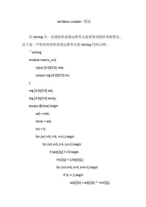
在Verilog中,实现矩阵求逆运算单元需要使用线性查找算法。
以下是一个简单的矩阵求逆运算单元的Verilog代码示例:```verilog
module matrix_inv(
input [3:0][3:0] mat,
output reg [3:0][3:0] inv
);
reg [3:0][3:0] adj;
reg [3:0][3:0] temp;
always @(mat) begin
adj = mat;
temp = adj;
inv = 0;
for (int i=0; i<4; i=i+1) begin
for (int j=0; j<4; j=j+1) begin
if (adj[i][j] != 0) begin
inv[i][j] = 1/adj[i][j];
for (int k=0; k<4; k=k+1) begin
if (k != j) begin
adj[i][k] = adj[i][k] * -inv[i][j];
end
end
end else begin
inv[i][j] = 0;
end
end
end
end
endmodule
```
这个模块接受一个4x4的矩阵作为输入,并输出其逆矩阵。
它使用线性查找算法来计算逆矩阵,该算法通过迭代地更新输入矩阵的每个元素来计算逆矩阵。
注意,这个模块没有进行错误检查,例如检查输入矩阵是否可逆。
在实际应用中,您可能需要添加额外的逻辑来处理这些情况。
verilog 获取稀疏矩阵求逆算法

verilog 获取稀疏矩阵求逆算法
摘要:
1.引言
2.稀疏矩阵与逆矩阵
3.逆矩阵求解方法
4.基于Verilog 的求逆算法实现
5.总结
正文:
1.引言
矩阵求逆是线性代数中的一个重要概念,逆矩阵可以用于矩阵的行列式计算、线性方程组求解等。
对于稀疏矩阵,由于其特殊的结构,求逆算法相对于稠密矩阵更为高效。
本文将介绍一种基于Verilog 的稀疏矩阵求逆算法。
2.稀疏矩阵与逆矩阵
稀疏矩阵是一种特殊的矩阵,其非零元素占据较小的篇幅。
由于稀疏矩阵的特殊性,可以采用压缩存储的方式进行存储,从而节省空间。
逆矩阵是矩阵的一种逆运算,求逆矩阵的过程就是寻找一个矩阵,使得该矩阵与原矩阵的乘积等于单位矩阵。
3.逆矩阵求解方法
对于稀疏矩阵的求逆,常用的方法有高斯消元法、LU 分解法等。
这些方法都可以通过迭代的方式求解逆矩阵。
其中,LU 分解法由于具有较好的数值稳定性,在实际应用中更为广泛。
4.基于Verilog 的求逆算法实现
本文将以LU 分解法为例,介绍如何基于Verilog 实现稀疏矩阵求逆算法。
首先,需要对稀疏矩阵进行LU 分解,将矩阵分解为下三角矩阵与上三角矩阵的乘积。
然后,利用高斯消元法求解逆矩阵。
最后,将求得的逆矩阵进行存储。
5.总结
本文介绍了基于Verilog 的稀疏矩阵求逆算法,通过LU 分解法与高斯消元法实现。
该方法可以有效地应用于硬件实现中,对于稀疏矩阵的求解具有较高的效率。
下三角矩阵求逆矩阵的例子
下三角矩阵求逆矩阵的例子
1、上三角矩阵的逆矩阵
将上三角矩阵划分成块矩阵,如上图所示,则其逆矩阵结果如下回图。
答
2、下三角矩阵的逆矩阵
将下三角矩阵划分成块矩阵,如上图所示,则其逆矩阵结果如下图。
3、只有主对角线不为零的矩阵
主对角元素取倒数,原位置不变。
4、只有副对角线不为零的矩阵
副对角元素取倒数,位置颠倒。
示例如下:
扩展资料
矩阵求逆的求法
(1)初等变换法,通过初等变换将A矩阵变换成单位矩阵,则对应的单位矩阵变换成B矩阵,B矩阵即为A矩阵的逆矩阵,(A I)->(I B);
(2)伴随阵法,公式为:;
(3)利用定义求逆矩阵
设A、B都是n阶方阵,如果存在n阶方阵B使得AB=BA=E,则称A为可逆矩阵,而称B为A的逆矩阵。
(4)恒等变形法
恒等变形法求逆矩阵的理论依据为逆矩阵的定义,此方法也常用
与矩阵的理论推导上,就是通过恒等变形把要求的值化简出来,题目中的逆矩阵可以不求,利用,把题目中的逆矩阵化简掉。
基于Verilog的下三角矩阵求逆设计与实现
基于Verilog的下三角矩阵求逆设计与实现杨丰瑞1,熊军洲2(1.重庆重邮信科(集团)股份有限公司重庆400065)(2.重庆邮电大学通信与信息工程学院重庆400065)摘要:矩阵运算广泛应用于各类电路计算中,矩阵运算的硬件实现能够充分发挥硬件的速度和并行性,其中矩阵求逆是矩阵运算中重要的运算。
根据矩阵求逆算法的基本思想,本文提出了一种最大阶数可达16×16的矩阵求逆方案,通过硬件描述语言Verilog建模,用Design Compile进行综合及进行modelsim仿真,仿真结果表明这种设计结构能够正确的计算出下三角矩阵的逆矩阵。
关键词:矩阵求逆,Verilog, 实现【中图分类号】TN492 【文献标识码】ADesign and Implementation of Inverse Down Triangle Matrix Calculation Based on VerilogYang Fengrui1,Xiong Junzhou2(1.Chongqing Chongyou Information Technolog (Group)CO.,LTD.Chongqing)(2.Chongqing University Of Post and TelecommunicationsSchool Of Communication and Information Engineering,Chongqing) Abstract: Matrix operation is widely used in different kinds of circuit calculation. Hardware implementation of matrix operation can fully realize the speed and parallel of the hardware. Matrix inversion is a kind of very important matrix operation. According to the algorithm of inverse matrix calculation ,this article gives a design on inverse matrix which can reach a biggest rand of 16×16.The system is described in Verilog, which is compiled by Design Compile and verified in modelsim. The result shows that this design structure can be used for inverse matrix calculation.Key words: inverse matrix; Verilog; implementation1 引言矩阵运算是数字信号处理领域的基本操作,广泛应用于各类电路计算当中。
下三角复矩阵求逆的ASIC 设计及实现
下三角复矩阵求逆的ASIC设计及实现熊洋郑建宏重庆邮电大学 400065摘要:本论文提出了一种便于ASIC实现的矩阵求逆算法,可以完成对1到16维下三角复矩阵的求逆运算,并用Verilog硬件描述语言进行实现。
利用SMIC 0.13um工艺库和Synopsys 公司的Design Compiler工具对代码进行了综合,并进行了低功耗优化,最后使用Modelsim 工具对代码进行了仿真验证,得到的结果同C代码模拟的结果完全一致,证明本模块完全可以达到预期目的。
关键词:ASIC;矩阵求逆;下三角复矩阵;Verilog;综合;仿真ASIC Designing and Implementation of Lower Triangular Complex Matrix InverseXiong Yang Zheng JianhongChong Qing University of Posts and Telecommunications 400065Abstract:This Paper presents a kind of matrix inverse arithmetic suitable for ASIC implementation, which could process 1~16 dimension lower triangular complex matrix, and is coded by Verilog HDL. Using SMIC 0.13um process library,we synthesis the codes by Design Compiler and optimize the power. At last, we verify the function of the module using Modelsim, and the result of Modelsim simulation is consonant with c code simulation, which prove that our module achieve anticipative goals.Key words:ASIC;matrix inverse;lower triangular complex matrix;Verilog;Synthesis;simulation 1、概述矩阵运算是很多科学运算和工程运用中的常见运算,大多数科学计算都可以归结为矩阵问题,在实际工程项目中更是如此。
一种下三角复矩阵求逆方法的IP设计与实现
一种下三角复矩阵求逆方法的IP设计与实现佚名【期刊名称】《电子测试》【年(卷),期】2011(000)010【摘要】矩阵运算是很多科学运算中的常见运算,矩阵求逆在矩阵运算中有着举足轻重的作用,在数字信号处理过程中常常被运用到。
本文根据一种便于ASIC实现的矩阵求逆算法,提出了一种最大阶数为16阶复矩阵求逆的IP设计串行实现方法。
首先本文分析了算法的特殊性,然后提出此IP设计方法的实现思路和结构,最后用Verilog语言进行实现并用Modelsim进行仿真验证,证明了此方法能够正确实现高速流水的矩阵求逆运算,并且易于修改矩阵规模,控制更方便,实现更容易,适用于工程应用及科学研究。
%Matrix inversion plays a significant role in matrix operation area,which is always applied to digital signal processing.Based on a matrix algorithm which suitable for ASIC implementation,this paper present a serial design method,whose maximum dimension is 16.Firstly it analyzed the particularity of the algorithm,then it offered the design structure and method.Finally it was coded by verilog HDL and simulated using Modelsim3.0,which proves this method can rapidly correctly finish the operation and easier to modify,control,and suitable for the engineering application and scientific research.【总页数】4页(P9-12)【正文语种】中文【中图分类】TP311.52【相关文献】1.三角矩阵求逆的一种方法 [J], 杨明顺2.基于Verilog的下三角矩阵求逆设计与实现 [J], 杨丰瑞;熊军洲3.一种基于约化因子上三角矩阵求逆的FPGA实现方法 [J], 周杨;王佳薇;黄志洪;杨海钢4.下三角复矩阵求逆的ASIC设计及实现 [J], 熊洋;郑建宏5.一种基于约化因子上三角矩阵求逆的FPGA实现方法 [J], 周杨;王佳薇;黄志洪;杨海钢;;;;;;因版权原因,仅展示原文概要,查看原文内容请购买。
任意维矩阵求逆的FPGA设计与实现
任意维矩阵求逆的FPGA设计与实现王锐胡永华马亮杜福慧(合肥工业大学微电子设计研究所 wangrui@)摘要:矩阵运算广泛应用于各类电路计算中,矩阵运算的硬件实现能够充分发挥硬件的速度和并行性。
其中矩阵求逆是矩阵运算中重要的运算,针对目前多维矩阵难以设计的情况,本文提出了一种任意维矩阵求逆的硬件实现方法,实验达到了预期目标。
任意维矩阵求逆的硬件实现在数字信号处理领域将具有广泛的应用前景。
关键字:任意维矩阵求逆 LU分解现场可编程门阵列Abstract: Matrix operation is widely used in different kinds of circuit calculation. Hardware implementation of matrix operation can fully realize the speed and parallel of the hardware. Matrix inversion is a kind of very important matrix operation. Due to the difficulty of design of multi-dimension matrix, a kind of hardware implementation method of arbitrary dimension matrix inversion is proposed and the result of the experiment can meet the requirement. The hardware implementation of arbitrary dimension matrix inversion would have more widely application prospect in digital signal processing field.Keyword: arbitrary dimension matrix inversion LU decomposition FPGA 矩阵运算是数字信号处理领域内的基本操作,广泛应用于各类电路计算中,在诸如DCT 变换、LDPC编解码领域应用非常广泛。
- 1、下载文档前请自行甄别文档内容的完整性,平台不提供额外的编辑、内容补充、找答案等附加服务。
- 2、"仅部分预览"的文档,不可在线预览部分如存在完整性等问题,可反馈申请退款(可完整预览的文档不适用该条件!)。
- 3、如文档侵犯您的权益,请联系客服反馈,我们会尽快为您处理(人工客服工作时间:9:00-18:30)。
基于Verilog的下三角矩阵求逆设计与实现杨丰瑞1,熊军洲2(1.重庆重邮信科(集团)股份有限公司重庆400065)(2.重庆邮电大学通信与信息工程学院重庆400065)摘要:矩阵运算广泛应用于各类电路计算中,矩阵运算的硬件实现能够充分发挥硬件的速度和并行性,其中矩阵求逆是矩阵运算中重要的运算。
根据矩阵求逆算法的基本思想,本文提出了一种最大阶数可达16×16的矩阵求逆方案,通过硬件描述语言Verilog建模,用Design Compile进行综合及进行modelsim仿真,仿真结果表明这种设计结构能够正确的计算出下三角矩阵的逆矩阵。
关键词:矩阵求逆,Verilog, 实现【中图分类号】TN492 【文献标识码】ADesign and Implementation of Inverse Down Triangle Matrix Calculation Based on VerilogYang Fengrui1,Xiong Junzhou2(1.Chongqing Chongyou Information Technolog (Group)CO.,LTD.Chongqing)(2.Chongqing University Of Post and TelecommunicationsSchool Of Communication and Information Engineering,Chongqing) Abstract: Matrix operation is widely used in different kinds of circuit calculation. Hardware implementation of matrix operation can fully realize the speed and parallel of the hardware. Matrix inversion is a kind of very important matrix operation. According to the algorithm of inverse matrix calculation ,this article gives a design on inverse matrix which can reach a biggest rand of 16×16.The system is described in Verilog, which is compiled by Design Compile and verified in modelsim. The result shows that this design structure can be used for inverse matrix calculation.Key words: inverse matrix; Verilog; implementation1 引言矩阵运算是数字信号处理领域的基本操作,广泛应用于各类电路计算当中。
而矩阵求逆的难点在于矩阵求逆。
目前传统的矩阵求逆算法多用处理器串行计算来实现,严重制约着计算速度的提高。
为此,作者在研究并行处理结构和并行算法[1~2]的基础上,试图寻求一种适合硬件实现的求逆算法及其硬件结构。
此外,在专用集成电路设计方面我国起步较晚,在矩阵求逆的硬件实现方面的研究还不多。
随着集成电路制造工艺的提高,采用大量超大规模集成单元和微处理器构成多处理器并行系统已经成为提高计算速度的有效手段。
因而,矩阵求逆算法的研究实现有着十分重要的意义。
由于可逆矩阵都可以通过LU分解分成一个上三角矩阵和一个下三角矩阵[3],而要求的原矩阵的逆可以通过这两个三角矩阵的逆相乘得到[4],所以本文主要探讨的是下三角矩阵求逆的硬件实现。
2 算法介绍假设以下矩阵A 为原矩阵,1-A 是A 的逆矩阵,n 是A 的维数。
则: 110...001 (00)0 (00)0...1E A A -==⨯11112122212212120...00...0...0...0..............................n n nn n n nn a b a a b b a a a b b b =⨯ 由矩阵的乘法可知:,,,()i i j i k k j k jc a b ==*∑ (j<=i )而:0,=j i c (j i ≠); 1,=j i c ( j i = )根椐以上可知,可首先得到一些初始值:i i i i a b ,,/1= (i=1,2,…,n)然后可得出计算1-A 其他值的递推公式: ∑-=*-=1,,,,)(1i j k j k k i i i j i b a a b =1,,,()i i i i k k j k j b a b -=-*∑(i=1,2,…,n ; j=1,2….,i -1) 3 硬件实现3.1 总体设计结构本文所设计的矩阵求逆算法模块(matrix_top )共分为:接口模块(regif ),控制模块(ctrl),地址产生模块(addrgen),运算处理模块(proc ),和存储器模块(mem )。
其中存储器模块包括输入存储器模块(inbuf )和输出存储器模块(outbuf )。
总体结构图如图1所示:图1 总体结构图3.2 模块介绍3.2.1接口模块(regif)与外部的ZSP总线相连实现接口功能,数据通过接口模块写入到输入存储器或是控制寄存器中,当zio_sel为高电平时,写入数据到输入寄存器中,当zio_sel 为低电平时,写入数据到控制寄存器中,控制寄存器指示矩阵的维数和启动信号;当运算完成,数据都存放到输出寄存器后,此接口模块产生一个中断,通知ZSP从输出存储器(outbuf)中读出数据。
3.2.2控制模块(ctrl)为一个状态数为5的有限状态机,产生整个运算状态信息,控制运算的进行。
如图2所示图2 ctrl模块中状态机示意图当处于IDLE(即空闲)状态时,表示运算还未开始或是运算结束,此时finish信号为零。
一旦接收到来自接口模块的启动运算信号时,即转为CHECK状态,CHECK状态用于对原矩阵对角线上的数据求倒数,并找出最大值,根据所求的最大值计算出矩阵归一化时的移位个数,当求得此归一化的移位个数时,即转为DIAG状态。
DIAG状态表示对原矩阵对角线上的数据进行求倒运算,并根据归一化的移动个数进行截位,此运算完成后,即转为OTHER 状态,根据前面所述原理计算非对角线上的数据,全部数据运算完毕后,发出一个finish 信号,并转入FINISH状态。
FINISH状态根据信号finish的反馈信号,对finish信号进行清零,并转入到下一个状态,即IDLE状态。
3.2.3地址产生模块(addrgen)该模块主要用于产生读写数据的地址。
当处于CHECK和DIAG两个状态时,该模块产生原矩阵对角线上的地址和逆矩阵对角线的地址。
当处于计算非对角线的数据时,该模块根据矩阵在存储器中存放的位置(矩阵数据在存储器中按行存放)及计算原理,依次计算时原矩阵和逆矩阵的读地址和逆矩阵的写数据地址。
3.2.4处理模块(proc)对矩阵进行求逆运算,从输入存储器中读取原矩阵的信息,求逆后将所得的结果数据存入到输出矩阵中。
直接利用存在的除法器和乘法器[5~6],根据前述算法介绍部分的计算原理,进行运算。
先调用除法器作流水线除法,求出逆矩阵对角线上的数据(对原矩阵对角线上的数据求倒数),并找出其中最大值,根据此最大值的符号位数计算归一化的移位个数;然后计算逆矩阵对角线上的数据,利用所求的归一化移位个数进行归一化操作,并将结果存入到输出存储器;计算完对角线上的数据之后,根据算法介绍部分的算法描述调用乘法器将非对角线上的数据算出并归一化存入到输出存储器。
3.2.5 存储器模块(mem)分为输入存储器(inbuf)和输出存储器(outbuf)两个部分。
输入存储器(inbuf)用来接收ZSP传送的数据,存放为原矩阵,只存放矩阵的下三角阵,在运算的过程中,输入存储器根据地址产生模块(addrgen)产生的地址和片选信号将数据依次输出到处理模块(proc);输出存储器(outbuf)用来接收从处理模块(proc)送来的结果数据,存放为逆矩阵,只存放矩阵的下三角阵,在运算的过程中,输出存储器也不断地根据地址产生模块(addrgen)产生的地址和片选信号将数据依次输出到处理模块(proc)进行计算,输出存储器(outbuf)的数据可由ZSP直接读出。
3.3硬件模块实现框图如图3所示图3 硬件模块实现框图3.4 硬件资源及运行时间直接利用已设计的乘法器和除法器,用到的乘法器资源为6个,除法器资源为1个。
该矩阵求逆电路完成一次16×16的矩阵求逆运算所需时钟周期为1000个时钟周期。
4仿真验证电路的仿真采用MENTOR公司的ModelSim5.5d软件,图4为输入一个16×16的原矩阵,图5为该原矩阵下所求得的结果,可以看出,当计算完毕,发出一个中断信号matrix_irq (为高电平),然后zrdata依次读出输出存储器(outbuf)中的数据,经验结果是正确的。
图4 modelsim仿真波形(输入原矩阵)图5 modelsim仿真波形(输出逆矩阵)5 结束语本文提出了一种用于下三角矩阵求逆的并行计算阵列,阵列中各处理模块单元之间的互联规则简单,此设计能够充分发挥硬件的速度,且易于修改矩阵的规模,适用于科学研究和工程应用中矩阵求逆的实时求解。
作者用Verilog语言对本设计进行了描述[7],并用SYNOPSYS公司的DC及modelsim对其进行综合和仿真,最终结果表明此硬件结构能够正确地求解出下三角矩阵的逆。
参考文献[1] K.Hwang, F.A.Briggs. Computer Architecture and Parallel Processing. McGraw-Hill,1994.[2] 陈国良. 并行算法的设计与分析. 高等教育出版社,1994.[3] 黄廷祝,钟守铭,李正良. 矩阵理论[M]. 北京:高等教育出版社,2003.[4] 同济大学数学教研室. 线性代数[M]. 北京:高等教育出版社,1993.[5] Ma G K, Taylor F J. Multiplier Policies for Digital Signal Processing[J]. IEEE A SSPMagazine,1990,7(1):6~20.[6] 傅志晖,程东方,梅其元等. 32位浮点阵列乘法器的设计及算法比较.微电子学,2003,33(3).[7] 夏宇闻. Verilog数字系统设计教程.第2版.北京航空航天大学出版社,2008.作者简介:杨丰瑞(1963-),男,重庆人,教授,主研移动通信,电信新业务等;熊军洲(1985-),男,湖北安陆人,硕士生,主研移动通信。