精华隆EP210报警主机说明书
消防主机操作及火警处理说明---HCP演示幻灯片
手动消防启动 盘
状态指示灯 主机键盘区
联动单元 主机电源
4
4/13/2020
消防主机主要组成及基本操作说明
1.液晶显示屏
火警记录,显示 火警的日期,时
间等相关信息
液晶显示屏位于消防主机正面左上角,其主要作用为:
1.提供火警、联动机故障等相关信息;
5
2.为操作主机提供视觉保障。
4/13/2020
火灾扑灭后协助火灾调查、
16
处理及灾后复原工作 4/13/2020
The END
------- THANK YOU !
17
4/13/2020
警报声。 启动,停动键—— 启动,停动相应设备; 屏蔽,取消屏蔽—— 屏蔽,取消屏蔽相应设备; 启动控制键—— 选择启动方式,有自动,手动,部分自动三种选择; 自检键—— 按下此键后系统将进行和开机时相同的声光及电源检查; 窗口切换键—— 在控制器处于分屏和全屏显示状态下都可以进行当前窗口 切换;选择状态下,按窗口切换键可退出; 记录检查键—— 系统将显示运行记录信息;
当有报警状况发生时,图形显示装置上会显示出报警地点、报警时间、 报警状况(手报、探头或联动等)等相关信息,故警卫室值班人员必须熟悉 全厂区分布状况,熟知报警点发生地点(配备消防主机点位图)。
8
4/13/2020
消防主机主要组成及基本操作说明
4. 手动消防启动盘
设备提示信息 命令灯 回答灯 手动键
要启动一个设备,首先根据手动消防启动盘的透明窗内的提示信息 找到要启动的设备对应的单元,按下这个单元的手动键,命令灯点亮, 启动命令发出;若再次按下该键则命令灯熄灭,启动命令被终止。
9
4/13/2020
消防主机主要组成及基本操作说明
报警与对讲联接方案

- 1 -报警与对讲联接设计方案design proposal中华人民共和国公共安全行业标准制定企业GA/T 761-2008项目名称:天津嘉华星港国际公司名称:北京市拓安联创智能科技有限公司Beijingtuoan Technology Development co.,ltd公司地址:北京市朝阳区双桥路金隅可乐A座509室公司电话: 8610-6570 3544 8610-6570 2544售后服务热线:目录第一章工程概述........................................................................ 错误!未定义书签。
第二章目标 (3)第三章系统设计的基本原则 (3)3.1 实用性 (3)3.2先进性 (4)3.3 可靠性 (4)3.4可扩展性 (4)3.5方便易用性 (4)第四章设计范围 (5)第五章设计依据 (5)第六章室内智能报警系统 (6)6.1系统概述及需求分析 (6)6.2针对系统方案的产品选型及产品参数 (8)6.3 系统报警点统计 (12)第七章系统结构及组成............................................................ 错误!未定义书签。
7.1与楼宇对讲有线连接示意图 (13)7.2与楼宇对讲无线连接示意图 (13)7.3独立报警系统连接示意图 (14)第八章系统布线及供电要求 (14)8.1系统电源的供电 (14)8.2系统布线的要求 (14)别墅项目报警初步方案一、工程概览根据别墅的具体情况。
在本智能化系统工程设计上,将按照有关领导提出的要求结合现阶段安全防范智能化设计标准进行设计。
二、设计目标本系统设计中严格依照中华人民共和国公共安全行业标准、公安局技防办关于安全防范系统的有关规定,用最佳设计方案体现最高的性能价值比,应用现代安全防范技术,建立必要的安全防范体系,同时综合运用各种现代技术手段,创造一个安全、舒适、以人为本的生活居住环境,这是我们的设计指导思想,也是我们的基本出发点和追求的目标。
CNC210S说明
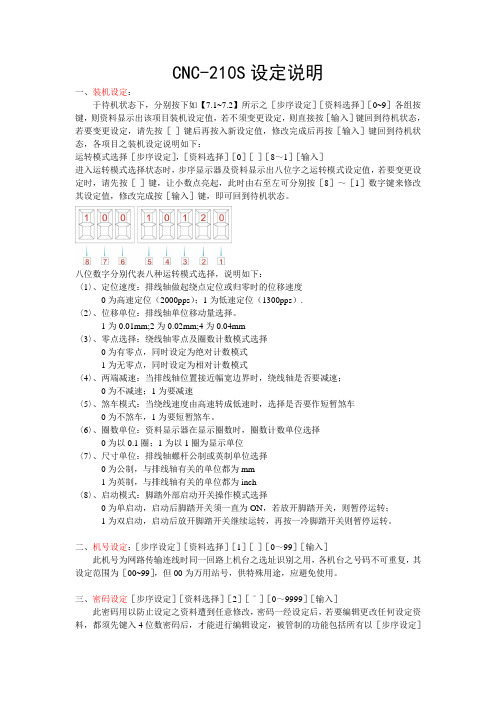
CNC-210S设定说明一、装机设定:于待机状态下,分别按下如【7.1~7.2】所示之[步序设定][资料选择][0~9]各组按键,则资料显示出该项目装机设定值,若不须变更设定,则直接按[输入]键回到待机状态,若要变更设定,请先按[-]键后再按入新设定值,修改完成后再按[输入]键回到待机状态,各项目之装机设定说明如下:运转模式选择[步序设定],[资料选择][0][-][8~1][输入]进入运转模式选择状态时,步序显示器及资料显示出八位字之运转模式设定值,若要变更设定时,请先按[-]键,让小数点亮起,此时由右至左可分别按[8]~[1]数字键来修改其设定值,修改完成按[输入]键,即可回到待机状态。
八位数字分别代表八种运转模式选择,说明如下:〈1〉、定位速度:排线轴做起绕点定位或归零时的位移速度0为高速定位(2000pps);1为低速定位(1300pps).〈2〉、位移单位:排线轴单位移动量选择。
1为0.01mm;2为0.02mm;4为0.04mm〈3〉、零点选择:绕线轴零点及圈数计数模式选择0为有零点,同时设定为绝对计数模式1为无零点,同时设定为相对计数模式〈4〉、两端减速:当排线轴位置接近幅宽边界时,绕线轴是否要减速;0为不减速;1为要减速〈5〉、煞车模式:当绕线速度由高速转成低速时,选择是否要作短暂煞车0为不煞车,1为要短暂煞车。
〈6〉、圈数单位:资料显示器在显示圈数时,圈数计数单位选择0为以0.1圈;1为以1圈为显示单位〈7〉、尺寸单位:排线轴螺杆公制或英制单位选择0为公制,与排线轴有关的单位都为mm1为英制,与排线轴有关的单位都为inch〈8〉、启动模式:脚踏外部启动开关操作模式选择0为单启动,启动后脚踏开关须一直为ON,若放开脚踏开关,则暂停运转;1为双启动,启动后放开脚踏开关继续运转,再按一冷脚踏开关则暂停运转。
二、机号设定:[步序设定][资料选择][1][-][0~99][输入]此机号为网路传输连线时同一回路上机台之选址识别之用,各机台之号码不可重复,其设定范围为[00~99],但00为万用站号,供特殊用途,应避免使用。
HD 210 产品说明说明书
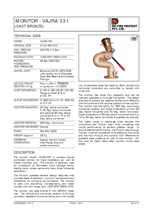
MONITOR - VAJRA 331(CAST BRONZE)TECHNICAL DATAMODEL VAJRA 331NOMINAL SIZE 3 Inch (80 MM) MAX. SERVICE 200 PSI (14 Bar)PRESSURE MAXIMUM FLOW 1000 GPM (3800 LPM) FACTORY 35 Bar (500 PSI)HYDROSTATIC TEST PRESSURESWIVEL JOINT Bronze to IS:318 / ASTM B 62 with double row of Stainless Steel Ball Bearing and Grease Fittings NOZZLE THRUST Flow in LPM X √Pressure REACTION IN Kg.in Kg./sq.cm. X 0.0228INLET CONNECTION 3” OR 4” (80 NB OR 100 NB) Flange to ANSI B16.5#150, F .F .OUTLET CONNECTION 3” BSP (M) or 2-1/2” BSP (M) or 2.5 NH MONITOR ELEVATION 90 Deg. above horizontal & 45 Deg. below horizontal and optional 85 Deg. above horizontal & 0 or 15 or 30Deg. below horizontalMONITOR ROTATION 360 Deg. continuous MONITOR MOVEMENT ManualFINISHRed RAL 3000WEIGHT (Approx) 33 KgORDERING Specify Monitor Model, INFORMATION Inlet Flange Size andoutlet connectionDESCRIPTIONThe monitor Model- VAJRA-331 is durable manual controlled monitor for fixed installation as well as trailer mounted unit. The monitor is generally used for protection of flammable liquid storage tanks, loading racks, dykes marine and many other Industrial application.The Monitor possess several design features that provides ease of operation, minimum maintenance and resistance to corrosive environments. The monitor is used with aspirating, non-aspirating and water nozzles with flow range upto 1000 GPM (3800 LPM).The monitor has cast bronze 3 inch (80MM) water way. The vertical and horizontal rotation is through corrosion resistant bronze swiveling joint with doublerow of stainless steel ball bearing. Both vertical and horizontal movement are controlled by handle with twist lock.The monitor has large flow capability and can be manually operated by a single fire fighter . The design ensures to prevent jet reaction forces from effecting the horizontal and the vertical position of the monitor . The monitor has the ability for 360 deg. continuous horizontal rotation and angle of elevation is from 90 deg. above horizontal and 45 deg. below horizontal. Angle of elevation of 85 deg. above horizontal and 0 or 15 or 30 deg. below horizontal is available as optional.The water vanes in discharge tube reduces the turbulence and friction loss, thus increasing the nozzle performance to achieve greater range. T o ensure desired performance, the friction loss through monitor must be considered while selecting the nozzle and the flow through the monitor with reference to available base pressure at inlet of the monitor . For flow and jet reach data refer monitor nozzle data sheet.INSTALLATION, TESTING AND MAINTENANCEThe monitor must be installed and operated carefully by a trained person, having good knowledge of equipment. Before assembly of the monitor to the supply piping, thoroughly flush the piping with water to avoid sand, residue, welding slag or other debris hindering the proper functioning of the monitor .After few initial successful tests, an authorized person must be trained to perform the inspection and testing of the monitor .The monitor should be ready for use. T o achieve this condition, scheduled inspection and maintenance operation should be performed and it must be recorded in the maintenance register book indicating the requirement or recommendation. The recommended maintenance, procedure must be followed as given in the manual and also as per the local authority having jurisdiction.It is recommended to carry out weekly physical inspection of the monitor . The inspection should verify that no damage has taken place to any component and the monitor is ready for use.Carry out functional test every month for the flow, regular rotation in horizontal and vertical plane for the entire operating range to observe any leakage.Periodic proper greasing through grease nipple provided on bearing, worm wheel and worm shaft must be ensured. Use water resistant low friction synthetic grease. Lubrication is required for smooth operation.Each monitor must be operated with the full flow in accordance to the guidelines of the organisation having local jurisdiction.The owner is responsible for maintaining the equipment in proper operating condition.CAUTIONA trained personnel for fire fighting must use the monitor . Appropriate guidance & training must be given to reduce the risk or injury.The nozzle must be fixed to the monitor carefully, The flange bolts must be tightened uniformly.The piping must be able to with stand the horizontal reaction force. Serious injury to personnel and equipment can result from improper installation.When installing monitor it is critical that flange bolts be tightened uniformly to prevent cocking of the monitor relative to the flange or valve.Before flowing water from monitor , check that all personnel are out of stream path and stream direction will not cause avoidable property damage.Application of water or foam on an electric appliance can cause serious injury.The water supply to monitor must be increased /decreased gradually to prevent possible water hammer occurrence.PART LISTELEVATIONSIDE VIEWNote :1) Monitor inlet flange standard size is 80 NB ( 3”) or 100NB (4”) to ANSI B16.5, 150#.2) All dimensions in mm and are approximate.3) Nozzle suitable to this Monitor is VARSHA 30,VARSHA 40, VARSHA HF30, VARSHA HF40.LIMITED WARRANTYHD FIRE PROTECT PVT. L TD. hereby referred to as HD FIRE warrants to the original purchaser of the fire protection products manufactured by HD FIRE and to any other person to whom such equipment is transferred, that such products will be free from defect in material and workmanship under normal use and care, for two (2) years from the date of shipment by HD FIRE. Products or Components supplied or used by HD FIRE, but manufactured by others, are warranted only to the extent of the manufacturer’s warranty. No warranty is given for product or components which have been subject to misuse, improper installation, corrosion, unauthorized repair , alteration or un-maintained. HD FIRE shall not be responsible for system design errors or improper installation or inaccurate or incomplete information supplied by buyer or buyer’s representatives.HD FIRE will repair or replace defective material free of charge, which is returned to our factory, transportation charge prepaid, provided after our inspection the material is found to have been defective at the time of initial shipment from our works. HD FIRE shall not be liable for any incidental or consequential loss, damage or expense arising directly or indirectly from the use of the product including damages for injury to person, damages to property and penalties resulting from any products and components manufactured by HD FIRE. HD FIRE shall not be liable for any damages or labour charges or expense in making repair or adjustment to the product. HD FIRE shall not be liable for any damages or charges sustained in the adaptation or use of its engineering data & services. In no event shall HD Fire’s product liability exceed an amount equal to the sale price.The foregoing warranty is exclusive and in lieu of all other warranties and representation whether expressed, implied, oral or written, including but not limited to, any implied warranties or merchantability or fitness for a particular purpose. All such other warranties and representations are hereby cancelled.NOTICE :The equipment presented in this bulletin is to be installed in accordance with the latest publication standards of NFPA or other similar organisations and also with the provision of government codes or ordinances wherever applicable.The information provided by us is to the best of our knowledge and belief, and consist of general guidelines only. Site handling and installation control is not in our scope. Hence we give no guarantee for result and take no liability for damages, loss or penalties whatsoever , resulting from our suggestion, information, recommendation or damages due to our product.Product development is a continuous programme of HD FIRE PROTECT PVT. L TD. and hence the right to modify any specification without prior notice is reserved with the company.D-6/2, ROAD NO. 34, WAGLE INDUSTRIAL ESTATE, THANE 400 604, INDIA.• TEL: + (91) 22 2158 2600 • FAX: +(91) 22 2158 2602•EMAIL:***************• WEB: HD FIRE PROTECT PVT . LTD.Protecting What Matters Most to You。
210系列紧凑网络开关快速引导说明书

210 SERIES COMPACT NETWORK SWITCHESQuick Start GuideAN-210-SW-C-8-PoE210 Series Compact Network SwitchesQuick Start GuideFCC WarningChanges or modifications not expressly approved by the party responsible for compliance could void the user’s authority to operate the equipment. This device complies with Part 15 of the FCC Rules. Operation is subject to the following two conditions: This device may not cause harmful interference, andThis device must accept any interference received, including interference that may cause undesired operation.12NOTE: This equipment has been tested and found to comply with the limits for a class B digital device, pursuant to part 15 of the FCC Rules. These limits are designed to provide reasonable protection against harmful interference in a residential installation. This equipment generates, uses and can radiate radio frequency energy and if not installed and used in accordance with the instructions, may cause harm-ful interference to radio communications. However, there is no guarantee that interference will not occur in a particular installation. If this equipment does cause harmful interference to radio or television reception, which can be determined by turning the equipment off and on, the user is encouraged to try to correct the interference by one or more of the following measures.Reorient or relocate the receiving antennaIncrease the separation between the equipment and receiverConnect the equipment into an outlet on a circuit different from that to which the receiver is connected Consult the dealer or an experienced radio/TV technician for helpThis equipment has been verified to comply with the limits for a class B computing device, pursuant to FCC Rules. In order to maintain compliance with FCC regulations, shielded cables must be used with this equipment. Operation with non-approved equipment or unshielded cables is likely to result in interference to radio and TV reception. The user is cautioned that changes and modifications made to the equip-ment without the approval of manufacturer could void the user’s authority to operate this equipment.CE WarningThis is a Class B product. In a domestic environment, this product may cause radio interference, in which case the user may be required to take adequate measures.UL StatementAll models have been evaluated by UL.This device is intended for indoor use only. It should not be connected to an Ethernet network with outside plant routing.The user must use the class I optical transceivers which conform to U.S. code of federal regulation, 21 CFR 1040. This equipment is only to be connected to PoE networks without routing to outside plants.Ensure the power cord is connected to a socket-outlet with earthing connection, or equivalent.NOTE: Maximum PoE output power of this equipment is 65W.Welcome to Araknis Networks™Thank you for choosing an Araknis 210-series Compact Network Switch. This PoE-powered switch features Gigabit connectivity on all ports, updated modern aesthetics, and a level of control (Websmart) rarely seen in managedsolutions. The Araknis 210-series switch is a sleek and highly capable addition to any network.Features• Gigabit Ethernet• 8 × 802.3af/at PoE-OUT Ports• 2 × SFP Uplink 1000BASE-X Ports• Multi-mounting can design• Websmart switch• OvrC enabledDimensions (W x H x D)• 8 Port: 12.71" x 1.50" x 4.13"Operating T emperature• 32–122°F (0–50°C)Step 1: UnboxSwitch Quick Start GuideRubber Feet (4)Structured WiringCan Mounting Kitw/ Push Pins (2) Shelf Mount Kit:4 sets of:• Screw: M3 x 8mm• Hollow Screw: M6 x 8mm• Nut: M6 nut 4 wall anchors with M3 x16mm screwsSpare Can MountingPush Pins (4)Body: 8.5mm(D), 10.4mm(L),6.35mm(W)Pin: 8.5mm(D), 18.2mm(L),3.7mm(W)Step 2: Install210 compact switches feature several mounting options for easy setup in any scenario. See the following pages forspecific instructions.Shelf(use included rubber feet)WallStructured Wiring CanIEC Power CableMounting Shelf Installation(Due to its width, this model should span two mounting shelves. We do not recommend using only one.)NOTE: Connect SFP ports using Araknis SFP adapters for RJ45 or multi-mode fiber cables. SFP adapters sold separately.Step 3: ConnectComputerStep 4: PoE BudgetThe power budget for delivering Power over Ethernet limits the total number of watts available between all of the ports (limited to 30W total consumption on each port). Add the total number of watts consumed by all connected PoE devices to ensure that every thing can be powered, as illustrated in the example below.ModelPoE Budget AN-210-SW-C-8-POE65WT otal PoE Device Consumption =45W PoE Budget Left Available=20WT otal PoE Budget Available=65W 8W +++8W 12W14WStep 5: VerifyPower LED –O n: system is up. Off: system is down.1Gbps LED –O n: port connected at 1Gbps speed.Off: port is connected at 10/100Mbps speed.Link/Act LED –O n: port is connected to another device.Blinking: packets are running through the port.Off: port is not connected to a device.Step 6: Claim on OvrCWeb BrowserMobileOvrC provides remote firmware upgrades, real-time notifications, and intuitive customer management, right fromyour computer or mobile device. Setup is plug-and-play, with no port forwarding or DDNS address required. T o addthis device to your OvrC account:Connect the switch to the network (Internet access required).Log Into OvrC () or load the OvrC app.Add the device (MAC address and Service T ag numbers needed for authentication).(RJ-45 LEDs only)210 Series Compact Network SwitchesQuick Start GuidePro Tip: Rebooting the Switchfor 5 seconds, then release. The switch will power cycle andthe front status lights will flash.Factory Reset –P ress and hold the RESET button for 15 seconds until all LEDs turn solid. The switch will reboot and be reset to factorydefault settings.© 2020 Araknis Networks®200306-0951WarningThis product can expose you to chemicals including carbon black, which is known to the State of California to cause cancer. For more information go to .2-Y ear Limited WarrantyAraknis Networks® products have a 2-Y ear Limited Warranty. This warranty includes parts and labor repairs on all components found to be defective in material or workmanship under normal conditions of use. This warranty shall not apply to products that have been abused, modified, or disassembled. Products to be repaired under this warranty must be returned to a designated service center with prior notification and an assigned return authorization (RA) number. Contact technical support for an RA number.Contact InformationTechnical Support (866) 838-5052The latest version of this QSG may be found on the productpage support tab.。
报警主机使用说明书(中文版)

报警主机使用说明书(中文版)注意事项:1.安装场所远离高温的热源和环境,避免阳光直接照射。
为确保本机的正常散热,应避开通风不良的场所。
为了防止电击和失火,请勿将本机放置于易燃、易爆的场所。
小心轻放本机避免强烈碰撞、振动等,避免安装在会剧烈震动的场所。
MV2516智能报警主机避免在过冷、过热的场所间相互搬动本机,以免机器内部产生结露,影响机器的使用寿命。
(ALARM CONTROLLER)2.避免电击和失火使用说明书切记勿用湿手触摸电源开关和本机。
勿将液体溅落在本机上,以免造成机器内部短路或失火。
(中文版第一版)勿将其它设备直接放置于本机上部。
安装过程中进行接线或改线时,都应将电源断开,预防触电。
重要提示:为了避免损坏,请勿自动拆开机壳,必须委托有资格有专业维修人员在指定的维修单位进行维修。
清洁装置时,请勿使用强力清洗剂,当有灰尘时用干布擦拭装置。
不得在电源电压过高和过低的场合下使用该本机。
务请通读本使用说明书,以便您掌握如何正确使用本机。
当您读本说明书后,请把它妥善保存好,以备日后参考。
如果需要维修,请在当地与经本公司授权的维修站联系。
环境防护:本机符合国家电磁辐射标准,对人体无电磁辐射伤害。
申明:产品的发行和销售由原始购买者在许可协议条款下使用;未经允许,任何单位和个人不得将该产品全部或部分复制、再生或翻译深圳市智敏科技有限公司成其它机器可读形式的电子媒介;SHEN ZHEN ZHI MIN TECHNOLOGY CO.,LTD. 本手册若有任何修改恕不另行通知;Copyright 2000-2004. All Rights Reserved.因软件版本升级而造成的与本手册不符,以软件为准。
智能报警主机目 录ALARM CONTROLLER1.设备概述………………………………………………………………3 1.设备概述:2.设备介绍………………………………………………………………3 智能报警主机是采用微处理器控制的报警信息采集和输出设备。
连接手册
第 5 章 连接 I/O 接口………………………………………………………………… 27
5.1 I/O 接口概略……………………………………………………………………………
2
7
5.1.1 I/O 接口的种类……………………………………………………………………… 27
5.1.2 I/O 单元的连接举例………………………………………………………………… 27
4.有关电池的注意事项 电池出现电压偏低报警时,请将程序、刀具数据、机械参数存储到输入/输出设备中,然后更换电 池。 请不要将电池短路、充电、加热、焚烧或分解。 请按照地方法规处理使用过的电池。
Ⅰ连接说明
「目录」
第 1 章 概要 ……………………………………………………………………………… 1
第 2 章 构成……………………………………………………………………………… 2
DASEN-3i
连接手册
请仔细阅读本手册,并作为后续参考
大森数控
安全注意事项
为了正确使用系统,在系统安装,运行,编程,维修,检查之前,一定要熟读机床厂家提供的规格说明,本
用户手册,相关说明书及附加文件。
在使用之前,请熟练掌握本数控装置的全部知识,安全注意事项及警告。
本说明书将安全注意事项划分为 危险 , 警告 , 注意
注意 2.安装方面的注意事项
请在非易燃材料上安装控制单元或操作面板。若直接或就近在易燃材料上安装可能会引起火灾。 请务必严守安装的方向。 请不要安装,运行已经损坏或缺少部件的控制单元,操作面板。 请不要将螺钉,金属屑等导电物质或油等易燃物质混入控制单元,操作面板。 控制单元,操作面板都为精密设备,请注意防止碰摔,强力冲撞。 请不要将操作面板安装在有冷却液的位置。
GEC2000安装使用说明书
5.1 菜单操作的基本方法 .............................................................................................................17 5.2 进入系统功能 .........................................................................................................................17 5.3 系统自检 .................................................................................................................................19 5.4 地址设定 .................................................................................................................................20 5.5 部件信息 .................................................................................................................................21 5.6 数据采样 .................................................................................................................................22 5.7 工程安装 .................................................................................................................................23 5.8 事件记录 .................................................................................................................................24 5.9 校 时 ......................................................................................................................................27 5.10 编 程 ..................................................................................................................................28 5.10.1 回路编程 .........................................................................................................................28 5.10.2 联动编程: .....................................................................................................................33 第四部分 用户须知 ...............................................................................................................................44 第6章 第7章 一般故障处理 .....................................................................................................................45 注意事项 .............................................................................................................................46
FASTRON VC-210 控制器产品说明书
MANAGER CopyFAST Lit. Part No. 229-51311 Rev. B (MANAGER) 07/13/2006 PITCO L20-306 Rev 0 11/06 Page 1 Process Controller – (FASTRON.)® VC-210(FASTRON.) VC-210 ControllerThe (FASTRON.) VC-210 process controller is used to control many different appliances. Each controller can time up to 20 products, store messages, alarm names, cooking and filtering parameters, and has shortening management capabilities.FAST is not liable for any use of product not in accordance with FAST’s installation and operating instructions.Before using this equipment or for any questions on the operation of the appliance, consult and follow all instructions and safety warnings found in the appliance operators’ manual supplied from the manufacturer of the appliance.Process Controllers FAST Lit. Part No. 229-51311 Rev. B (MANAGER) 07/13/2006 PITCO L20-306 Rev 0 11/06 P age 2Installing the (FASTRON.) VC-210 ControllerREMOVE EXISTING (FASTRON.)1 Unplug fryer2 Remove the two (2) screws from the bezel securing the (FASTRON.) controller in the header cavity. Remove the bezel.3 Remove the controller by disconnecting the 9-pin and 2-pin connectors. (Several pressure and split vat fryers will have additional connectors that will have to be removed.)INSTALL THE NEW (FASTRON.)1 Remove the two (2) 5/32” screws from the NEW controller.2 Plug the 9- and 2-pin connectors into the corresponding connectors in the fryer. (Several pressure and split vat fryers will have additional connectors that will have to be connected.)NOTE: The 3-pin connector coming from the controller has no corresponding connector. It is for future use.3 Insert the controller back into the fryer header cavity. Re-attach the bezel (frame) to the controller.4Secure the controller and bezel to the fryer header with the two (2) 5/32” hex screws provided.Process ControllersFAST Lit. Part No. 229-51311 Rev. B (MANAGER) 07/13/2006 PITCO L20-306 Rev 0 11/06 Page 3 Parts Description – (FASTRON.)VC-210 ControllerPart Function1. SCAN key • Used for recipe review during idle.• Used to review time remaining during multiple cooks (press & hold)2. EXIT FILL key • Depressing this key for three seconds will force a filterthat will reset all internal filter counters.3. VFD (Vacuum Fluorescent Display) • Bright blue for easy viewing. Displays programming and cook cycle information.4. Programming Buttons • Used to access programming mode and changeparameters.5. Changeable Menu Strip • Menu items are printed directly on easy-to-change menustrip.6. SCK® Link LED • LED will light when communications is enabled.7. IR Port (Infrared) – Optional • Used to download programming from wireless device.8. Product Buttons • Used to activate cook cycles and for certainprogramming functions.9. Tech Support/Serial # Window • Easy access to FAST tech support center. 10. Indicator Lights • Light up when product key is activated. 11. EXIT COOL key • Used to exit setback (COOL) mode. Also used to cancelhold alarms, as well as scroll through active holds when held down.Process ControllersGlossary of Terms and FeaturesDaylight Savings Time: Some countries have a one-hour change to their clocks in the Spring and Fall to allow for more daylight hours. Spring / Fall programming as described in this manual allows the operator to quickly and easily change the time by one hour without accessing the other polish programmable parameters.Instant On: When turned "On" this feature automatically causes the electric element or gas burner to turn "On" for a pre-determined time (0-60 seconds) when a cook cycle is started. This helps prevent excessive temperature drop when product is introduced to the fryer, thereby ensuring product quality.Polish: The circulation of the shortening through the filter for a period of time, as opposed to filtering which passes the shortening through the filter only once.Polish Later: The polish later command is active at all times UNLESS the delay time is programmed to ZERO. The polish later command is used if a fryer has entered the polish command, yet it is needed to produce product at that time. The delay time programmed will start counting, and at the end of the delay time the operator will be forced to polish the shortening. The delay can only be activated once.Polish Now: The “polish now” command is active at all times once the event times are activated. If a Polish Now is entered and completed within 3 hours of a scheduled event polish time, the event polish time will be canceled. This allows an operator to polish a fryer and get credit for the polish before the actual polish command sounds. This is useful in a store with many fryers where the operator wants to "get ahead" of the polish work if they have time available.Polish Scheme: There are 4 events. An event is a polish sequence. (See pages 17 & 18) Stagger Times: (This is for the 2nd event only)Some operators prefer all the fryers to enter polish at the same time. In this case, all fryers start beeping at the same time and the need to polish is obvious. The delay command can then be used to delay those fryers that are needed for cooking. Other operators prefer a staggering of the Polish activation time (less noise in the kitchen, and can polish in a sequence). Staggered time programming as described in this manual allows the operator to quickly and easily customize their preference without accessing the other polish programmable parameters. Staggers are available in 15-minute increments from the set polish time up 45 minutes.FAST Lit. Part No. 229-51311 Rev. B (MANAGER) 07/13/2006 PITCO L20-306 Rev 0 11/06 Page 4Process ControllersFAST Lit. Part No. 229-51311 Rev. B (MANAGER) 07/13/2006 PITCO L20-306 Rev 0 11/06 Page 5 Using the (FASTRON.) VC-210Controller: Operational Test Procedure1 Plug fryer into electrical source2NOTE: This scrolling can be bypassed by pressing SCAN.The controller will scroll through the following: a. Appliance Type b. Software # c. Download # d. Current Date e. Time of Day f. SCK Address g. “COOL” 3 Turn the fryer power switch on. 4 Press the EXIT COOL key once. 5 Press any illuminated product key.6 The cook cycle will count down in the display.NOTE: A cook cycle can be canceled by pressing and holding the active product key for 3 seconds. Pressing the product key for less than 3 seconds will not cancel the cook cycle.If the cycle is canceled during the first 25% of the cook time, the cook cycle simply gets canceled and the display shows either “COOL” or the actual temperature, depending on the appliance. Canceling the cycle during the last 75% of the cook time will either put the controller in the filter mode or subtract one from its cycle count toward filter lockout.Process ControllersFAST Lit. Part No. 229-51311 Rev. B (MANAGER) 07/13/2006 PITCO L20-306 Rev 0 11/06 Page 6 Operating the (FASTRON.) VC-210 ControllerRECIPE REVIEW — Quickly see what is programmed for each product key1. Press the SCAN key.2. Select any product key previously programmed–LED will be lit above the key.3. Press the DOWN arrow key to scroll through the list.4. Press SCAN to exit.VIEW TEMPERATURE SETTING1. Press the TEMP key ‘once’ to view Actual temperature, or2. Press the TEMP key ‘twice’ to view Set temperature.ACTIVATING THE POLISH FEATURE1. To Polish ‘NOW ’, press and hold the EXIT COOL and EXIT FILL keys at the same time.2. To Polish ‘LATER ’, press and hold the SCAN and EXIT FILL keys at the same time. NOTE: Polishwill only be delayed IF a non-zero polish delay time is set.DISPLAY TIME OF DAY —2 second display of the current time of day. NOTE: Can only be done if the controller is at COOL or idle mode.1.Press and hold the SCAN and EXIT COOL keys at the same time.DISPLAY APPLIANCE TYPE AND DOWNLOAD INFORMATION —2 second scrolling display of the Appliance Type, Software #, Download #, Current Date, Time of Day and SCK Address.1.Press the SCAN and TEMP keys at the same time.Process ControllersFAST Lit. Part No. 229-51311 Rev. B (MANAGER) 07/13/2006 PITCO L20-306 Rev 0 11/06 Page 7 Programming the (FASTRON.) VC-210 ControllerProgramming Mode for the Vision Controller is entered by pressing the “P” key for three (3) seconds. Multiple programming modes are available on the VC-210 as follows:Passcode Access LevelS y s t e mR e c i p eP r o d N a m e L i b r a r yA l a r m L i b r a r yC l o c k /D a t eS M S A c t i v a t eI n s t a n t O nS C K A d d r e s s6647 Manager X X X X X X XNOTES:• Pressing the “P” key saves the previous parameter.• If no key is pressed within 2 minutes while in Programming mode, the controller will automatically return to idle mode.• All scrolling will loop back through allowed values.Process ControllersFAST Lit. Part No. 229-51311 Rev. B (MANAGER) 07/13/2006 PITCO L20-306 Rev 0 11/06 Page 8 Changing the Menu Strip on a (FASTRON.) VC-210 Process Controller1 • Turn off the fryer power.2 • With a flat screwdriver, remove the two screws that secure the bezel of the VC-210 in place. Remove the bezel.3 • Remove the existing menu strip(s) by lifting the tab andpulling the menu strip out from the right side of the controller.4 • Using the tab as a guide, slide the new menu strip in. 5 • Replace the bezel and screws that secure it to the controller. 6• Turn on the fryer power.Replacement Parts ListPart Number Description 150-10202 1/4-20X3/4" SLOT RD HD BLK O 150-11025 NUT 1/4-20 TINNERMAN SPRING 214-50291 SHEETMETAL BEZEL 214-50660-57 OVERLAY 214-51003-57 MENU STRIPProcess ControllersFAST Lit. Part No. 229-51311 Rev. B (MANAGER) 07/13/2006 PITCO L20-306 Rev 0 11/06 Page 9 SYSTEM PROGRAMMING (6647)KEY PRESS DISPLAYACTION1 Enter Program modeOR• To enter programming mode,press and hold the "P" key for 3 seconds.• Scroll Down to Programming. • Press the “P” key to lock in your entry.2Enter pass codeENTER CODE****• Enter pass code 6 6 4 7. • Press the “P” key when “System” is displayed.• Press the “P” key again to enter System Programming.3Confirm or Select Appliance TypeORAPPLIANCE TYPE XXXXXXXX • Press the LEFT or RIGHT arrow keys to select from a pre-programmed list of appliances.NOTE: Changing appliancetype clears all current recipe programs.• Press the “P” key to lock in your entry4 Select LanguageORSELECT LANGUAGE (English, Other) • Press the LEFT or RIGHT arrow key to select language• Press the “P” key to lock in yourentryNOTE: ‘Other’ is downloadable.Process Controllers FAST Lit. Part No. 229-51311 Rev. B (MANAGER) 07/13/2006 PITCO L20-306 Rev 0 11/06 Page 105 Set Tone Level ORTONE LEVEL (None, 1, 2, 3, 4, 5)• Press the LEFT or RIGHT arrow keys to select a tone level. At each level the controller will continuously sound the selected tone.• Press the “P” key to lock in your entry6Set Temperature ModeORTEMPERATURE F = FAHRENHEIT or C = CELSIUS • Press the LEFT or RIGHT arrowkeys to select the method that all temperatures will be displayed in.• Press the “P” key to lock in your entry7 Set Profile TimingORPROFILE TIMING (NO, YES)• Press the LEFT or RIGHT arrow keys to activate Profile Timing to monitor each individual stage of the cook time.• Press the “P” key to lock in your entry8 Program Setback TimeSETBACK TIMEHH:MM• Press the numbered product keys to select the time in hh:mm format for activating Setback mode.• Press the “P” key to lock in your entry9Program Setback TemperatureSETBACK TEMPXXX• Press the numbered product keys to select the Setback temperature in the range of 200 to 375°F. • Press the “P” key to lock in your entry10 Program Global FilterLockoutGLOBAL FLTR CNTXX(“0” to “99”)•Type in the number of cooksallowed on all keys beforeforcing Filtering by pressing theappropriate numbered productkey(s). The range is 0 to 99,where 0 means No GlobalFiltering.•Press the “P” key to lock in yourentry11 Set Repair FunctionORREPAIR FUNCTION(YES, NO)•Press the LEFT or RIGHT arrowkeys to select whether the RepairFunction will be active or not.•Press the “P” key to lock in yourentry12 Set Repair Fail Time REPAIR FAIL TIMEMM:SSThis option will only appear if theRepair Function is enabled.•Press the numbers to set RepairFail time in minutes/seconds.The range is 0 to 59:59 minutes.•Press the “P” key to lock in yourentry13 Set Daylight SavingsModeORDAYLIGHT SAVINGS(SPRING, FALL)•Press the LEFT or RIGHT arrowkeys to select the appropriateDaylight Savings choice.•Press the “P” key to lock in yourentry14 Set Stagger TimeORSELECT STAGGER(00 MINUTES,15 MINUTES,30 MINUTES,45 MINUTES,60 MINUTES)•Press the LEFT or RIGHT arrowkeys to select the SMS staggertime.•Press the “P” key to lock in yourentry15 Set # of RQI TrackersOR# RQI TRACKERSNONE, 1-30•Press the LEFT or RIGHT arrowkeys to select number of RQITrackers.•Press the “P” key to lock in yourentryFAST Lit. Part No. 229-51311 Rev. B (MANAGER) 07/13/2006 PITCO L20-306 Rev 0 11/06 Page 11FAST Lit. Part No. 229-51311 Rev. B (MANAGER) 07/13/2006 PITCO L20-306 Rev 0 11/06 Page 1216Set SCK Status Sound ORSCK STATUS SOUND YES or NO • Press the LEFT or RIGHT arrowkeys to change.• Press the “P” key to lock in yourchoice.17Set Communication Error DisplayORCOM ERROR DISP YES or NO • Press the LEFT or RIGHT arrowkeys to change.• Press the “P” key to lock in yourchoice.18 Exit Program ModeOREXIT• Press the UP or DOWN arrow keys to scroll to “Exit.”19• Press the “P” key to return to idle mode.PRODUCT OR ALARM NAME LIBRARIES (6647)KEY PRESS DISPLAY ACTION1 Enter Program modeOR•To enter programming mode,press and hold the "P" key for 3seconds.•Scroll Down to Programming.•Press the “P” key to lock in yourentry.2 Enter Pass Code SYSTEMPROGRAMMING****•Enter pass code 6 6 4 7.•Press the “P” key to lock in yourentry.3ORPROD NAME LIBOrALARM LIB•Scroll to “Prod Name Lib” or“Alarm Lib”•Press the “P” key to advance.From this point, you can either MODIFY an Existing Name, or ADD a New Name.4a MODIFY or ADD anExisting Product or AlarmNameORProd Name LibxxxxxxxxORAlarm Name Libxxxx•Start spelling the name(predictive method) usingkeys 1-10, OR•Use the UP and DOWNarrow keys to scroll throughthe library (traditionalmethod).4b •Once name is located, pressthe SCAN key to togglefrom predictive text input totraditional text input.4cOR•Use the LEFT and RIGHTarrow keys to move theFAST Lit. Part No. 229-51311 Rev. B (MANAGER) 07/13/2006 PITCO L20-306 Rev 0 11/06 Page 13cursor.•Press “Exit Fill” to togglebetween Upper and Lowercase.•“Exit Cool” can be used toclear the existing productname.•Press the “P” key tocomplete.4dORSAVE LIBRARYMODIFY, ADD,CANCEL•Press the LEFT or RIGHTarrow keys to select“Modify” or “Add.”•Press the “P” key.NOTE: Selecting “Cancel”allows you to exit withoutmaking any changes.4e Exit Program ModeOREXIT •Press the UP or DOWNarrow keys to scroll to“Exit.”FAST Lit. Part No. 229-51311 Rev. B (MANAGER) 07/13/2006 PITCO L20-306 Rev 0 11/06 Page 14CLOCK/DATE PROGRAMMING (6647)KEY PRESS DISPLAY ACTION1 Enter Program modeOR•To enter programming mode,press and hold the "P" key for 3seconds.•Scroll to Programming.•Press the “P” key.•The display will prompt user toenter a pass code.2 Enter Pass CodeORCLOCK/DATE****•Enter pass code 6 6 4 7.•Press the “P” key to lock in yourentry.•Scroll to Clock/Date•Press the “P” key to advance.FAST Lit. Part No. 229-51311 Rev. B (MANAGER) 07/13/2006 PITCO L20-306 Rev 0 11/06 Page 153 Set Time of DayORTIME OF DAYHH:MMCURRENT YEAR“XXXX”CURRENT MONTH“XXXXXXXXX”CURRENT DATE“XX”CURRENT DAY“XXXXXXXX”•Use the numbered product keysto set the time of day. The rangeis from 00:00 to 23:59.•Press the “P” key.•Press the LEFT and RIGHTarrow keys to set the Year.•Press the “P” key.•Press the LEFT and RIGHTarrow keys to set the currentMonth.•Press the “P” key.•Press the LEFT and RIGHTarrow keys to set the currentDate.•Press the “P” key.•Press the LEFT and RIGHTarrow keys to set the Day.•Press the “P” key.4 Exit Clock/DateProgrammingOR•Scroll to Exit.•Press the “P” key to return to idlemode.FAST Lit. Part No. 229-51311 Rev. B (MANAGER) 07/13/2006 PITCO L20-306 Rev 0 11/06 Page 16FAST Lit. Part No. 229-51311 Rev. B (MANAGER) 07/13/2006 PITCO L20-306 Rev 0 11/06 Page 17 SMS ACTIVATION PROGRAMMING (6647)KEY PRESS DISPLAYACTION1 Enter Program modeORSMS ACTIVATE• To enter programming mode,press and hold the "P" key for 3 seconds.• Scroll to “Programming.” • Press the “P” key.• The display will prompt user to enter a pass code. 2Enter Pass CodeENTER CODE****• Enter pass code 6 6 4 7. • Press the “P” key to lock in your entry.• Scroll to “SMS Activate.” • Press the “P” key.3 Setting SMS Activation TimeNOTE: Depending on the scheme entered (see below), one of four SMS Activation times will be selected.3aSCHEME 1ORSet SMS TimingFor SMS use:• Event 1 = 7:00 A.M., 30 Min. Duration, 0 Hour Delay Event 2 = 2:00 P.M., 30 Min. Duration, 3 Hour DelayOR3b SCHEME 2ORSet SMS Timing For SMS use:• Event 1 = 7:00 A.M., 15 Min. Duration, 0 Hour Delay • Event 2 = 2:00 P.M., 15 Min. Duration, 3 Hour DelayOR3c SCHEME 3ORSet SMS Timing For SMS use:•Event 1 = 2:00 P.M., 15 Min.Duration, 3 Hour Delay•Event 2 = 8:00 P.M., 15 Min.Duration, 3 Hour DelayOR3d SCHEME 4ORSet SMS Timing For SMS use:•Event 1 = 2:00 P.M., 30 Min.Duration, 3 Hour Delay•Event 2 = 8:00 P.M., 30 Min.Duration, 3 Hour Delay4OREXIT •Press the “P” key to advance tonext step.•From SMS Activate, scroll toExit and press the “P” key.FAST Lit. Part No. 229-51311 Rev. B (MANAGER) 07/13/2006 PITCO L20-306 Rev 0 11/06 Page 18SET INSTANT ON (6647)KEY PRESS DISPLAY ACTION1 Enter Program modeOR•To enter programming mode,press and hold the "P" key for 3seconds.•Scroll to “Programming.”•Press the “P” key.•The display will prompt user toenter a pass code.2 Enter Pass Code ENTER CODE****•Enter pass code 6 6 4 7.•Press the “P” key to lock in yourentry.•Scroll to “Instant On.”•Press the “P” key.3 SELECT PRODUCTTO PROGRAM•Select a Product Key4 INSTANT ON:XX•Use Product Keys to enter 0-60.5 SELECT PRODUCTTO PROGRAM•To program additional products,select another product key.6 Exit Instant OnProgrammingOR•Scroll to Exit.•Press the “P” key to return to idlemode.FAST Lit. Part No. 229-51311 Rev. B (MANAGER) 07/13/2006 PITCO L20-306 Rev 0 11/06 Page 19SCK® ADDRESS (6647)KEY PRESS DISPLAY ACTION1 Enter Program ModeOR•To enter programming mode,press and hold the "P" key for 3seconds.•Scroll to Programming.•Press the “P” key.•The display will prompt user toenter a pass code.2 Enter Pass CodeORENTER CODE****•Enter pass code 6 6 4 7.•Press the “P” key to lock in yourentry.•Scroll to SCK Address.•Press “P” to advance.3 Set SCK AddressORSCK ADDRESSXX•Press the LEFT or RIGHT arrowkeys to scroll through the SCKaddress to be used for thiscontroller. The range is from 1 to31, or “Auto Assign.”•Press the “P” key to lock in yourselection.FAST Lit. Part No. 229-51311 Rev. B (MANAGER) 07/13/2006 PITCO L20-306 Rev 0 11/06 Page 204 Set SCK Node NETWORK NODESXX XX XX XX XX•The display will scroll inmarquee-style all SCK Nodescurrently in the system. Scrollingwill constantly be updated.•Press the “P” key to advance. 5 Exit SCKProgrammingOREXIT •Scroll to Exit.•Press the “P” key to return toidle.FAST Lit. Part No. 229-51311 Rev. B (MANAGER) 07/13/2006 PITCO L20-306 Rev 0 11/06 Page 21This page left intentionally blank.NOTES:FAST Lit. Part No. 229-51311 Rev. B (MANAGER) 07/13/2006 PITCO L20-306 Rev 0 11/06 Page 22This page left intentionally blank.NOTES:FAST Lit. Part No. 229-51311 Rev. B (MANAGER) 07/13/2006 PITCO L20-306 Rev 0 11/06 Page 23PATENTSThe products manufactured by FAST are protected underone or more of the following U.S. Patents:4,782,445 4,812,625 4,812,9634,864,498 4,911,068 4,920,9485,043,860 5,171,974 5,331,5755,539,671 5,711,606 5,723,8465,726,424 5,875,430 6,142,6666,339,930 6,401,467 6,505,5466,581,391 7,015,433Plus foreign patents and patents pending.Plus licensed patent 4,858,119Specifications subject to change without notice.This document contains confidential information. Thedissemination, publication, copying, or duplication of thisdocument without prior written authorization is strictlyprohibited.Food Automation -Service Techniques, Inc.905 Honeyspot RoadStratford, CT 06615-7147 USAPhone: +1-203-377-4414Sales: 1-800-FASTRONFax: +1-203-377-8187International Callers: +1-203-378-6860Toll-free technical support 24/7 from the U.S.,Canada, and Caribbean: 1-800-243-9271International offices are located in:China:+86139****4613Singapore: +65 98315927United Kingdom: +44 0 1268 544000FAST Lit. Part No. 229-51311 Rev. B (MANAGER) 07/13/2006 PITCO L20-306 Rev 0 11/06 Page 24。
JB-QBL-MN200火灾报警主机操作说明
SANJIANG ELECTRONICS
版本号:5008070921
JB-QBL-MN/200 火灾报警控制器(联动型)
§2-2-2 复示盘设置 在菜单中选择复示盘设置,将显示如下;
复示盘设置 编号:01 区号:01 类型:中文
登记:1 层号:01 显示:区显
通过← →可选择设置登记、区号、层号、类型、显示方式等设置项。当光标停留在类型
打印机登记:1
输入“1”为连接打印机, “0”为不连,根据需求设置,按“#”保存,返回按“*”
§2-3 报警设置
在系统主控平台选择菜单中报警设置,将显示如下:
报警设置
探头设置
联动设置
模块设置
调试平台
自动登录
当光棒停在探头设置按“#”键可对探测器进行设置。用↑ ↓ ← →可移动光棒的位置, 按“#”键可对当前光棒所在项进行设置,返回按“*”。
§2 主控平台的配置
本章中将详细介绍每一个主控平台配置的设置过程。
§2-1 进入系统
要对系统和其设备进行配置,如果系统处于主页并键盘关闭,按下“面板键盘”,然后
输入正确口令后按“#”,再按“1”,便进入此菜单。如果系统处于主页并键盘已打开则直接
按“1”进入。
主菜单如下:
主菜单
系统设置
手控设置
报警设置
右边的箭头→表示有下页,在本屏设置好后按→键进入下一屏界面为:
←探头设置
报警门限:1 预警门限:1
位置描述:
→
左边的箭头←表示可进入上一界面。在本屏设置好后按→键进入下一屏界面为:
←探头设置 位置:三江电子展厅 A1 区位汉字
:
上图中地址号为三位,第一位只能为0表示探测器,后面两位01-99号(在其它设置项中