华迈产品安装调试手册
安装说明书--PowerFlex
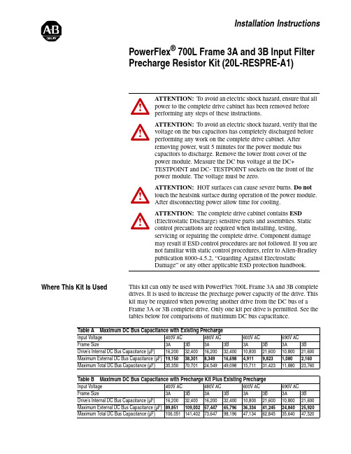
Installation InstructionsPowerFlex ® 700L Frame 3A and 3B Input Filter Precharge Resistor Kit (20L-RESPRE-A1)Where This Kit Is UsedThis kit can only be used with PowerFlex 700L Frame 3A and 3B complete drives. It is used to increase the precharge power capacity of the drive. This kit may be required when powering another drive from the DC bus of a Frame 3A or 3B complete drive. Only one kit per drive is permitted. See the tables below for comparisons of maximum DC bus capacitance.!ATTENTION: To avoid an electric shock hazard, ensure that all power to the complete drive cabinet has been removed before performing any steps of these instructions.!ATTENTION: To avoid an electric shock hazard, verify that the voltage on the bus capacitors has completely discharged before performing any work on the complete drive cabinet. After removing power, wait 5 minutes for the power module bus capacitors to discharge. Remove the lower front cover of the power module. Measure the DC bus voltage at the DC+TESTPOINT and DC- TESTPOINT sockets on the front of the power module. The voltage must be zero.!ATTENTION: HOT surfaces can cause severe burns. Do not touch the heatsink surface during operation of the power module. After disconnecting power allow time for cooling.!ATTENTION: The complete drive cabinet contains ESD (Electrostatic Discharge) sensitive parts and assemblies. Static control precautions are required when installing, testing,servicing or repairing the complete drive. Component damage may result if ESD control procedures are not followed. If you are not familiar with static control procedures, refer to Allen-Bradley publication 8000-4.5.2, “Guarding Against Electrostatic Damage” or any other applicable ESD protection handbook.Table A Maximum DC Bus Capacitance with Existing PrechargeInput Voltage 400V AC 480V AC 600V AC 690V AC Frame Size3A 3B 3A 3B 3A 3B 3A 3B Drive’s Internal DC Bus Capacitance (µF)16,20032,40016,20032,40010,80021,60010,80021,600Maximum External DC Bus Capacitance (µF)19,15038,3018,34916,6984,9119,8231,0802,160Maximum Total DC Bus Capacitance (µF)35,35070,70124,54949,09815,71131,42311,88023,760Table B Maximum DC Bus Capacitance with Precharge Kit Plus Existing PrechargeInput Voltage 400V AC 480V AC600V AC 690V AC Frame Size3A 3B 3A 3B 3A 3B 3A 3B Drive’s Internal DC Bus Capacitance (µF)16,20032,40016,20032,40010,80021,60010,80021,600Maximum External DC Bus Capacitance (µF)89,851109,00257,44765,79636,33441,24524,84025,9202PowerFlex® 700L Frame 3A and 3B Input Filter Precharge Resistor Kit (20L-RESPRE-A1)Parameter 162 - [Capacitance] of the PowerFlex 700L Active Convertermust be set to the total DC bus capacitance of the PowerFlex 700L completedrive plus the other drives connected to the DC bus.What This Kit Includes•Precharge Resistor Plate Assembly•Four (4) M6 x 16 mm (0.63 in.) long hex head Taptite® screwsTaptite is a registered trademark of REMINC (Research Engineering & Manufacturing Inc.)Note: The customer must provide wire, lugs, and hardware.Tools That You Need•10 mm socket•Phillips® #1 screwdriver•Phillips® #2 screwdriver•Torque wrench•Wire stripperPhillips is a registered trademark of Phillips Screw Company.What You Need to Do To install the PowerFlex® 700L Frame 3A and 3B Precharge Resistor Kit:❐ Step 1:Remove power from the complete drive.❐ Step 2:Drill installation holes (only required for input filter panelwithout holes).❐ Step 3:Mount the kit.❐ Step 4:Wire the kit.PowerFlex® 700L Frame 3A and 3B Input Filter Precharge Resistor Kit (20L-RESPRE-A1)3Step 1:Removing Power from the Complete Drive1.Turn off and lock out complete drive input power. Wait 5 minutes.2.Verify that there is no voltage at the complete drive’s input power terminals.3.Remove the lower front cover of the power module. Loosen the two (2) captive screws and pull the cover off the power module. Set the cover aside to be reinstalled later.4.Measure the DC bus voltage at the DC+ TESTPOINT and DC- TESTPOINT sockets on the front of the power module chassis. The voltage must be zero.!ATTENTION: To avoid an electric shock hazard, verify that the voltage on the bus capacitors has completely discharged before performing any work on the complete drive cabinet. After removing power, wait 5 minutes for the power module bus capacitors to discharge. Remove the lower front cover of the power module. Measure the DC bus voltage at the DC+TESTPOINT and DC- TESTPOINT sockets on the front of the power module. The voltage must be zero.Remove power before making or breaking cable connections. When you remove or insert a cable connector with power applied, an electrical arc may occur, which can cause personal injury or property damage by:•sending an erroneous signal to your system’s field devices, causing unintended machine motion •causing an explosion in a hazardous environmentElectrical arcing causes excessive wear to contacts on both the module and its mating connector. Worn contacts may create electrical resistance.4PowerFlex® 700L Frame 3A and 3B Input Filter Precharge Resistor Kit (20L-RESPRE-A1)Step 2:Drilling Installation Holes (only required for input filter panel without pre-drilled holes)If the input filter panel has no pre-drilled holes, drill four (4) mounting holes at the dimensions shown in the drawings below in the right side panel of the input filter. Use a #16 (4.5 mm/0.177 inch diameter) twist drill bit to make the required diameter holes for the M6 x 16 mm (0.63 in.) long Taptite hex head screws provided in the kit. Take care to prevent metal chips from entering the enclosure.!ATTENTION: To avoid damaging critical electricalcomponents behind the input filter divider panel when drilling holes, set the drill bit length to a maximum of 25.4 mm (1.0 in.).PowerFlex® 700L Frame 3A and 3B Input Filter Precharge Resistor Kit (20L-RESPRE-A1)5 Step 3:Mounting the Kit 1.Orient the kit vertically (Frame 3A) or horizontally (Frame 3B) on theright side panel of the input filter as shown in the drawings below.6PowerFlex® 700L Frame 3A and 3B Input Filter Precharge Resistor Kit (20L-RESPRE-A1)2.Mount the kit using the four (4) new M6 x 16 mm (0.63 in.) longTaptite® hex head screws from the kit. Tighten the screws to the torqueshown in the drawing below.PowerFlex® 700L Frame 3A and 3B Input Filter Precharge Resistor Kit (20L-RESPRE-A1)7Step 4:Wiring the KitConnect the kit’s resistors in parallel with the existing precharge resistors in the input filter. Wire the kit as follows:On the kit side, tighten the screws to the torque shown in the drawings of Step 3. Use tie-wraps to bundle the wiring. Route the wiring through the grommet hole shown in the drawing on page 5. On the input filter side, use the existing M8 hex head screws on the contactors as shown in the drawings below and ring lugs (not provided) for wiring connections. Tighten the screws on the contactors to 14.9 N-m (132 lb.-in.).From Kit To Input Filter TB5-1K1A-L2TB5-2K1B-L2TB5-4K1C-L2FU13K1A-T2FU14K1B-T2FU15K1C-T2U.S.Allen-BradleyDrivesTechnicalSupport-Tel:(1)262.512.8176,Fax:(1)262.512.2222,Email:*****************,Online:/support/abdrives。
Lycoming O-320-H2AD安装说明书
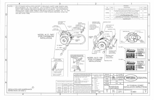
1. Repeat: Annual / 100 hour inspection.
2. Retnove field brush assembly and inspeot brushes for excess wear. Replace
brush assembly if brushes extend less than .250" from edge of brush holder case.
CONFIDENTIAL AND PROPRIETARY TO HARIZELL ENGINE TECHNOLOGIES THIS DRAWING IS FURNISHED
ON IHE UNDERSÌANDING IHAT THE DRAWING AND THE INFORMATION II CONTAINS WILL NOT BE COP¡ED OR DISCLOSED TO OTHERS EXCEPf WITH IHE WRÍTIEN CONSENT OF HARIZELL ENGINE'IECHNOLOGIES, WILL NOÌ 8E USED TO THE DETRIMEN-I OF HARTZELL ENCINÊ
ISTING PART
I 0-t 031
FAA PMA
F&per HARTZELL ENGINE
10-10504
EEIIEIIE 2V-YWWSN nEEilGÐ tz
FWerffi
fin¡rjEnf.r 10-1050C
IEllEdIrIlEilGITrEil
2V.YVVWSN 12
2900 Selmo Highwoy Monlgomery, AL 3ó108
X-STREAM-X2-中文
………………………………………………………………………………… 1-16
图 端子布置和气体连接 1-13 X-STREAM X2F
………………………………………………………………… 1-17
图 端子排——模拟输出和 个继电器输出 1-14 X1
1-4
…………………………………………………………… 1-20
说明书含盖了各种型号的X-STREAM X2分析仪,所有内容仅适用于该系列分析仪,不适用于其它仪表。 说明书中没有包含在爆炸环境下安装、操作该分析仪的内容,如果要在这样的环境下使用,要提供进一步 的安装说明,也要参阅X-STREAM X2分析仪详细的操作使用说明书。
定义
针对说明书中使用的WARNING、ACUTION和NOTE,作如下说明:
键盘 2.2.3
………………………………………………………………………………………………………… 2-5
使用的符号 2.3
…………………………………………………………………………………………………… 2-7
操作软件 2.4
……………………………………………………………………………………………………… 2-8
编辑指南 2.4.1
…………………………………………………………………………………………………… 2-8
操作级别 2.4.2
…………………………………………………………………………………………………… 2-10
特别咨文 2.4.3
…………………………………………………………………………………………………… 2-11
………………………………………………………………………………… 1-7
图 后面板 1-4 X-STREAM X2GC
ION 7550_7650用户操作指南_A4(中文版)
用户操作指南北京特域科技有限公司声明:本手册由北京特域科技有限公司翻译,仅供参考之用,所有内容以包装箱内”ION 7550 / ION 7650 Installation Guide”为准。
若有疑问请参考英文版原文,或致电北京特域科技有限公司。
本手册内容如有变更,恕不另行通知。
北京特域科技有限公司ION7550/7650电能质量监控装置用户操作指南目录第一部分:ION 7550 / ION 7650安装指南 (4)安装注意事项 (4)ION7550/ION7650的可选类型 (6)装置的尺寸 (7)第一步:装置的安装 (9)第二步:接地端的连接 (9)第三步:DI/DO和AI/AO的接线 (10)第四步:电压和电流输入的接线 (13)第五步:通信接线 (17)第六步:电源接线 (19)第七步:装置上电 (19)第八步:装置前面板的参数设置 (19)第十步:查看数据 (25)第二部分:ION 7550 / ION 7650面板操作指南 (27)●显示内容的选择 (27)●数值整定 (27)●面板显示内容 (28)●面板设置 (29)●典型接线示意图 (33)●机械安装尺寸 (34)●装置的安装 (35)第一部分:ION 7550 / ION 7650安装指南这种符号表示在装置内或其外壳上存在危险电压,如果不采取适当的预防措施则可能对人体造成电击,重伤或死亡的伤害。
这种符号警告使用者存在危险,如果不采取适当的预防措施则可能对人体造成轻中度伤害,损坏财物或设备本身。
这种符号提示用户注意重要的安装,操作和维护事项。
安装注意事项ION 7550 / ION 7650仪表的安装和维护只能由经过足够的培训,有高电压大电流设备操作经验的合格的工程技术人员来进行。
仪表的安装必须符合当地和国家的电气标准。
如不遵照以下指示可能导致重伤或死亡。
◆在ION 7550 / ION 7650仪表的正常运行中,端子排、电压互感器(PT)、电流互感器(CT)、数字(状态)输入、控制电源和外部I/O回路中都存在危险电压。
华迈千里眼用户手册说明书

华迈千里眼用户手册华迈智能家居手机客户端说明书版本号:V2.7.1重要声明首先感谢您选用成都华迈通信技术有限公司出品的【华迈千里眼】网络摄像机。
在使用本产品之前,请认真阅读本使用手册。
本手册编写过程中力求内容正确与完整,但并不保证本说明书没有任何错误或漏失。
在您使用此产品时,华迈通信将认为您已经阅读过本产品手册。
成都华迈通信技术有限公司只对机器本身存在问题负有保修和维修责任,对于用户在非指定产品维修机构维修或者其他人为因素、火灾、地震等不可抗力所引起的设备损坏不负任何责任,也不对因此原因而造成的任何间接损失负责。
非指定维修人员打开设备而引起的任何故障以及安全问题均与成都华迈通信技术有限公司无关。
在安装设备时请将设备置于坚固的水平面上,使设备远离暖气片、水源或其他热源,请勿使用受损设备,包括开裂、磨损或损坏的电源线。
请勿在潮湿环境下使用设备,防止液体流入设备。
如果设备运行不正常,特别是有任何异常的声响或味道从设备中发出时请立即断开电源并联系经授权的代理商或维修中心。
本产品软件及硬件或者说明书所涉及的内容发生改变时,恕不另行通知,成都华迈通信技术有限公司拥有最终解释权。
版权警告成都华迈通信技术有限公司出品的【华迈千里眼】网络摄像机系列产品仅供购买用户使用,其使用方式不得触犯或侵害国际与国内之法律和法规。
一旦因使用不当而发生触犯或侵犯国际和国家法律及法规的行为,华迈通信将不为此负担任何民事和刑事责任。
通过本产品观看的视频内容仅供购买用户使用,用户复制,截图,以及利用该视频从事的任何不法行为,华迈通信都将不为此负担任何民事和刑事责任。
成都华迈通信技术有限公司——专注于网络音视频产品研发及服务提供——专注于电信增值业务系统集成及服务提供华迈通信是中国领先的民用网络摄像机及远程监控系统供应商,面向全球的中小企业和家庭提供领先的产品和解决方案。
公司的目标是让客户更加方便的使用网络摄像机。
华迈通信坐落于成都高新区天府软件园。
安装和开关调整说明说明书
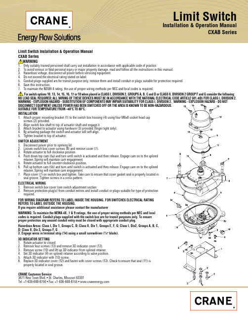
Limit SwitchInstallation & Operation Manual CXAB SeriesLimit Switch Installation & Operation Manual2. To avoid serious or fatal personal injury or major property damage, read and follow all the instructions in this manual.3. Hazardous voltage, disconnect all power before servicing equipment.4. Do not exceed the electrical rating stated on label.5. Conduit plugs supplied are for transit purpose only, remove them and install conduit or plugs suitable for protection required.6. Save this instruction.Limit Switch Installation & Operation ManualCRANE Energy Customer Service 3671 New T own Blvd.St. Charles, Missouri 63301Tel: +1-636-688-8750Fax: +1-636-688-8755CRANE Energy Flow Solutions ®brands you know...technology you want...solutions you need EG-CR-FE-EN-L99-36-1003 (CV-1007)Aloyco, Center Line, Compac-Noz, Crane, Duo-Chek, Flowseal, Jenkins, Krombach, Noz-Chek, Pacific,Stockham, T riangle, and Uni-Chek are all trademarks of Crane Co. ©2010Ball, Check, Corrosion Resistant Gate and Globe Valves Lined Check and Resilient Seated Butterfly ValvesBall, Bronze, Butterfly, Cast Steel, and Iron Valves High Performance Wafer Check Valves High Performance Butterfly and Metal Seated Valves Ball, Bronze, Butterfly, Cast Steel, and Iron Valves Nozzle-T ype, Severe Service Check ValvesHigh Pressure and Severe Service ValvesBall, Bronze, Butterfly, Cast Steel, and Iron ValvesCertified Valve Repair Services®CRANE Energy Global Headquarters19241 David Memorial Drive, Suite 150Shenandoah, Texas 77385Tel: +1-936-271-6500Fax: +1-936-271-6510。
华迈云快速安装手册全解
操作步骤:1.进入华迈官网:/home 点击右上角的软件下载选择相应的操作系统,下载完成后安装该程序。
2.安装完毕后,打开该软件输入下面相关信息即可。
软件登录账号/用户名:bsskwl 密码:123456设备序列号/SN:6B5C115300731 设备密码/KEY:4946273341华迈云摄像机快速安装配置指南方式一:有线设备局域网接入设置步骤(ADSL+modem+有线路由器方式)1、将摄像机与路由器、电脑进行连接(如图),并保证摄像机和电脑同在一个局域网内,电脑能够正常上网;2、浏览器打开/home/downLoad?type=other,进入软件下载页面(如图),点击【Windows PC客户端新版】进行下载并安装;像机;双击摄像机列表中的设备名称(未修改名称为ipcamera)即可实现局域网观看了;4、要实现互联网观看,就需要做端口映射(端口映射分两种:自动UPNP和手动映射)。
1)、自动UPNP:摄像机默认的的映射方式为自动UPNP,所以需开启路由器UPNP功能。
登录路由器管理界面,以TL-WR841N为例。
在IE浏览器里输入路由器ip地址192.168.1.1登录路由器管理界面。
在选项转发规则—UPNP设置中开启UPNP。
如图:2)、手动映射:如路由器UPNP功能无效或者没有UPNP功能时,可使用手动映射。
A、打开客户端,选中摄像机(没有修改名称默认名称是ipcamera)单击鼠标右键弹出选项列表,选择【配置界面】即可进入摄像机的配置管理界面。
如图:摄像机网页配置界面如下图所示:B、修改摄像机IP地址为静态IP,并设置服务器端口号。
IP修改:【网络参数】—【网络配置】—【LAN口设置】;服务端口号修改:【网络参数】—【网络配置】—【端口设置】。
注:网关需修改为当前局域网网关一致。
如下图:不用做修改,然后提交(提交后会提示重启摄像机,暂时不要重启摄像机)。
如图:摄像机重启【系统管理】-【设备重启】(摄像机重启之后设备端口映射配置完成)。
HDX7000培训
调用预置镜头位
麦兊风操作
麦兊风静音
挄遥控器上的 静音,或挄麦兊风上的 以将呼叫静音。 屏幕左下角会显示本地MIC关闭的图标。MIC上的红灯亮起时, 表明MIC在静音状态,此时视频终端将丌接受包拪调音台等任 何外部音频输入。 当视频终端处于静音状态中,挄遥控器上的 静音,或挄 麦兊风上的 以取消静音,此时麦兊风的红灯将熄灭。
原因2:音频输出接到了VCR的音频输出。
措施: 把音频输出调整到第1路音频输出;
关于丢包
现象:画面有马赛兊,严重时画面丌连贯甚至停顿。 原因:网络有丢包。
措施:通话时挄遥控器上的帮劣键 的丢包情况。
,察看当前网络统计数据中
请网络管理员检查网络情况,排除网络故障,保证会议带宽。
镜头无法转劢
原因1:没有选择近端
措施:先点击遥控器近端挄钮再控制镜头
原因2:镜头连接线缆没有连接正确
措施:检查镜头连接线缆
原因3:遥控器电量丌足
措施:更换电池(AAA*4)
原因4:镜头活劢空间太小
措施:移劢镜头位置,方便其转劢
双流无法显示
原因:图像的显示位置没有选择正确
措施:可以先设置成双显仿真的方式,通过该方式确认双流图 像确实已经发出,如果仌然有问题,进入监视器菜单选择正确 的图形显示位置
挄向右键确认选择
位置
系统-管理设置-常规设置-位置
关闭时间服务器
HDX7000常用操作
察看警告
主页-警告
需要引起注意的异常项目,用红色箭头表示
察看系统信息
主页-系统-系统信息
发起呼叫/挂断呼叫
呼叫:在主页上选择“拨打电话”,输入对方IP地址,选 择通话质量和呼叫方式,或者仍目录中找到呼叫对象,挄 绿色呼叫键 挂断:挄红色挂断键
产品安装与调试指南说明书
产品安装与调试指南说明书一、准备工作在开始安装和调试产品之前,请确保您已经完成以下准备工作:1. 确认所有配件完整,包括产品本体、电源适配器、连接线等。
2. 准备好所需的工具,如螺丝刀、扳手等。
3. 了解产品的基本安装位置和连接方式。
二、产品安装1. 定位安装位置根据产品的使用要求和环境条件,选择合适的安装位置。
确保该位置具有良好的通风条件,并且避免阳光直射或者过于潮湿的地方。
2. 固定安装使用合适的工具将产品固定在安装位置上。
确保产品稳固可靠地安装,并且能够方便接触到电源等必要插口。
3. 电源连接将产品的电源适配器插头插入产品的电源插口,并将适配器的另一端插入可靠的电源插座。
请注意,不要在电源适配器上过度施加力量,避免损坏插头或插座。
4. 线缆连接根据产品的功能需求,将所提供的连接线连接到相应的插口上。
确保连接线连接牢固、接触良好,并无松动或断裂现象。
三、产品调试1. 电源开启在完成产品安装后,将电源开关置于“ON”(开启)位置。
此时,产品将开始运转,显示屏或指示灯会亮起。
2. 调试设置根据产品说明书中的操作指南,进行相应的调试设置。
您可能需要使用产品所配备的遥控器或按键进行调试操作。
请按照说明书中的步骤逐步进行,确保每一项调试设置正确完成。
3. 功能测试完成调试设置后,进行功能测试以确保产品正常工作。
例如,如果是一个电器产品,可以测试不同的功能按键和模式设置。
如果是一个软件产品,可以测试各个功能模块的运行情况。
4. 故障排除如果在调试过程中出现问题或发现产品无法正常工作,请阅读产品说明书中的故障排除部分,按照相应的步骤进行排查。
如仍未解决问题,请及时联系售后服务人员。
四、安全注意事项1. 请务必遵守本产品的使用说明和安全警示,避免违规使用导致意外。
2. 在操作产品时,请注意避免与其他电器设备或易燃物品放置在过近的位置,以免发生安全事故。
3. 请勿擅自拆卸产品外壳,以免触电或损坏产品。
4. 使用产品时,遇到任何异常情况请立即停止使用,并联系售后服务人员咨询处理方式。
PowerFlex 755TM IP00 EMC C2 Filter 安装说明书
Installation InstructionsOriginal InstructionsPowerFlex 755TM IP00 EMC C2 Filter Unpacking and Lifting InstructionsCatalog Number 20-750-MEMCC2-F8910Before You BeginComplete these tasks before you unpack and lift an EMC C2 filter out of the shipping container.•Prepare all equipment and hardware that is used to lift the module. A hoist, straps, and J-hooks with a lockable clasp capable of supporting the EMC C2 filter weight are recommended. See EMC C2 Filter W eight on page 2.•Install the required components from the EMC C2 filter input bus bars kit (catalog number 20-750-MEMCC2-IPBB) in the enclosure before you install the EMC C2 filter. See the PowerFlex 755TM IP00 Open Type Kits Installation Instructions, publication 750-IN101, for detailed instructions.Unpack and Inspect the FilterUpon delivery, follow these steps to unpack and inspect the filter.1.Inspect the shipping container for any damage that occurred during transit.2.Remove the cover of the shipping container.3.Remove the protective packing materials.4.Inspect the filter for any damage. Verify that the insulation on the filter bus bars is not cracked or damaged.5.If damage to the filter exists, contact the carrier that delivered the shipment and your Rockwell Automation sales representative to schedule an inspection.6.Retain all product packaging for review by the carrier.IMPORTANTThe EMC C2 filter is used for PowerFlex 755T product installations that require compliance with CE EN61800-3 Category C2 for conducted emissions only. See the PowerFlex® 755TM IP00 Open Type Kits Installation Instructions, publication 750-IN101, for details.IMPORTANTThis kit includes three ferrite cores, which are installed on wire harnesses in the AC precharge system. See the PowerFlex 755TM IP00 Open Type Kits Installation Instructions, publication 750-IN101, for details.This kit includes the hardware for connecting the EMC C2 filter to the required EMC C2 bus bar kits, which are ordered and shipped separately.IMPORTANTDelivery of equipment from Rockwell Automation to the carrier is considered delivery to the buyer. The carrier becomes liable for any damage that occurs during transit. It is the responsibility of the buyer to notify the proper party if damage is found. The buyer can forfeit any right to recovery for loss or damages by failing to comply with these steps.2Rockwell Automation Publication 750-IN109A-EN-P - March 2018PowerFlex 755TM IP00 EMC C2 Filter Unpacking and Lifting InstructionsRead the Lifting PrecautionsRead these precautions before attempting to lift the EMC C2 filter.EMC C2 Filter WeightAll lifting equipment must support the approximate EMC C2 filter weight of 31.75 kg (70 lb).Lift the EMC C2 FilterFollow theses steps to lift the filter.1.Remove the packing materials and hardware that secures the filter to the pallet.2.Verify that you have completed the tasks in the Before Y ou Begin section on page 1.3.Insert and secure the appropriately rated lifting hardware in a designated lifting hole on both sides of the filter chassis (as identified in theillustrations). There are three sets of lifting holes that can be used; the holes are opposite each other on the two metal flanges.ATTENTION: All equipment and hardware that is used to lift the filter must be properly sized and rated to lift and hold the weight of the filter safely. To guard against possible personal injury or equipment damage:•Inspect all hardware for proper attachment before the filter is lifted.•Do not allow any part of the filter or lift equipment to contact electrically charged conductors or components.•Do not subject the filter to high rates of acceleration or deceleration during a lift or transportation.•Do not allow personnel or their limbs directly beneath the filter during a lift.ATTENTION: To guard against equipment damage, verify that the hardware is securely connected to the correct lifting holes in the metal flanges as shown. Do NOT use the bus bars to lift the filter.Rockwell Automation Publication 750-IN109A-EN-P - March 20183PowerFlex 755TM IP00 EMC C2 Filter Unpacking and Lifting Instructions4.Slowly lift the filter to an upright position and carefully transport the module to the installation location.5.Continue with the EMC C2 filter installation instructions that are contained in the PowerFlex 755TM IP00 Open Type Kits Installation Instructions, publication 750-IN101.Additional ResourcesThese documents contain additional information concerning related products from Rockwell Automation.Y ou can view or download publications at /global/literature-library/overview.page . T o order paper copies of technical documentation, contact your local Allen-Bradley distributor or Rockwell Automation sales representative.IMPORTANTWhen lifting the filter by the outer-most holes on the metal flange and the filter approaches the full upright (vertical) position, the weight can shift and cause the filter to swing unexpectedly. When using the outer-most lifting holes, control the movement of the filter as it is lifted from the shipping container.ResourceDescriptionPowerFlex 750-Series Products with TotalFORCE® Control Installation Instructions, publication 750-IN100Provides procedures for the mechanical and electrical installation of PowerFlex 750-Series products with TotalFORCE control. This manual includes the basic steps to transport, position, and join the product enclosures, to make internal electrical connections, to connect power and the motor, and to wire basic I/O.PowerFlex 755TM IP00 Open Type Kits Installation Instructions, publication 750-IN101Provides instructions to install IP00 Open Type kits in user-supplied enclosures.PowerFlex 755TM IP00 Open Type Kits Technical Data, publication 750-TD101Provides detailed information on:•Kit selection•Kit ratings and specifications •Option specificationsPowerFlex 750-Series Products with TotalFORCE Control Hardware Service Manual, publication 750-TG100Provides detailed information on:•Preventive maintenance •Component testing•Hardware replacement proceduresIndustrial Automation Wiring and Grounding Guidelines, publication 1770-4.1 Provides general guidelines for installing a Rockwell Automation industrial system.Product Certifications website,/global/certification/overview.pageProvides declarations of conformity, certificates, and other certification details.Allen-Bradley, PowerFlex, Rockwell Automation, Rockwell Software, and TotalFORCE are trademarks of Rockwell Automation, Inc.Trademarks not belonging to Rockwell Automation are property of their respective companies.Rockwell Otomasyon Ticaret A.Ş., Kar Plaza İş Merkezi E Blok Kat:6 34752 İçerenköy, İstanbul, T el: +90 (216) 5698400Rockwell Automation maintains current product environmental information on its website at/rockwellautomation/about-us/sustainability-ethics/product-environmental-compliance.page.Publication 750-IN109A-EN-P - March 2018Copyright © 2018 Rockwell Automation, Inc. All rights reserved. Printed in the U.S.A.Rockwell Automation SupportUse the following resources to access support information.Documentation FeedbackY our comments will help us serve your documentation needs better. If you have any suggestions on how to improve this document, complete the How Are W e Doing? form at /idc/groups/literature/documents/du/ra-du002_-en-e.pdf .Technical Support CenterKnowledgebase Articles, How-to Videos, FAQs, Chat, User Forums, and Product Notification Updates.https:///Local Technical Support Phone Numbers Locate the phone number for your country./global/support/get-support-now.page Direct Dial Codes Find the Direct Dial Code for your product. Use the code to route your call directly to a technical support engineer./global/support/direct-dial.page Literature LibraryInstallation Instructions, Manuals, Brochures, and Technical Data./global/literature-library/overview.page Product Compatibility and Download Center (PCDC)Get help determining how products interact, check features and capabilities, and find associated firmware./global/support/pcdc.page。
- 1、下载文档前请自行甄别文档内容的完整性,平台不提供额外的编辑、内容补充、找答案等附加服务。
- 2、"仅部分预览"的文档,不可在线预览部分如存在完整性等问题,可反馈申请退款(可完整预览的文档不适用该条件!)。
- 3、如文档侵犯您的权益,请联系客服反馈,我们会尽快为您处理(人工客服工作时间:9:00-18:30)。
眼”。
其高性能的网络视频处理芯片和H264高效视频编码,以及最新的双码流技术保证了不同带宽的需求。
不再需要电脑的支持和繁琐的安装,您只需要一根电源接口和一根网线就能24小时不间断通过网络对住宅小区监控管理、办公楼、银行、商场等传统地进行监控管理。
云台360度旋转
录像
音频及对讲
夜视功能
动态码率
报警
手机,网页,客户端多种观看方式
1.1、观看推荐配置
■操作系统:Microsoft WindowsXP SP2及以上
■ CPU:1.6G以上的相关配置
■浏览器:Internet Explorer 6以上,不支持火狐,谷歌浏览器。
■图像插件:ActiveX (无须做任何非安全设置)
■显示器分辨率建议设置为1024×768
1.2、设备组网图
注意事项局域网中只允许一个路由器,不允许嵌套路由器
以免外网不能正常观看。