500W并网逆变器设计
论文参考题目

论文参考题目(注:论文题目也可自行拟定)1、《硅片表面清洗》2、《光伏建筑一体化》3、《晶体硅太阳能电池产业化技术发展与展望》4、《多晶硅薄膜的制备方法》5、《论晶体硅太阳电池PECVD设备及发展趋势》6、《太阳能光伏发电系统与建筑一体化》6、《太阳能光伏电源》7、《薄膜太阳能电池研究进展》8、《光材料的应用与发展》9、《中国太阳能光伏产业发展前景》10、《太阳能光伏行业的前景与方向》11、《太阳能电站设计与分析》12、《论多晶硅企业要加强操作规程培训的必要性》13、《多晶硅薄膜太阳电池制备》14、《太阳能光伏发电原理与应用》15、《太阳电池的理论分析与研究》16、《晶体硅太阳电池表面钝化研究》17、《非晶硅太阳能电池研究》18、《太阳能的综合与应用》19、《从供应链角度浅谈光伏产业的问题与对策》20、《DSP的光伏电池最大功率点跟踪系统》21、《我国太阳能光伏产业的近期进展、挑战和对策建议》22、《浅析晶体硅扩散工艺》23、《硅基薄膜太阳电池的发展与未来》24、《多晶硅太阳电池制作工艺概述》25、《未来太阳能并网发电对电网的影响》26、《电池片原理及要求》26、《太阳能电池测试》27、《500W光伏并网逆变器设计》28、《硅太阳电池P-N结的形成》29、《丝网印刷》30、《平板式PECVD制备Si3N4减反射膜》31、《单晶硅太阳电池的表面结构》32、《太阳电池基本特性测试实验》33、《太阳电池减反射膜系统的研究》34、《光伏充电器设计》35、《独立式光伏发电系统MPPT策略研究》36、《硅的切削液的分析研究》37、《光伏VS实际应用一体化》38、《可控硅元件工作原理及特性》39、《论述太阳电池的烧结工艺与烧结炉结构》40、《中国发电的市场情况》41、《10kwp太阳能并网发电系统设计》42、《光伏产业和风能的研究》43、《太阳能车棚设计》44、《加快发展太阳能产业的思考》45、《超高效率太阳电池研究》46、《太阳电池减反射膜材料》http://111.75.204.5:88/nczk_web/Account/LogOn?ReturnUrl=%2fnczk_web%2f。
100KW,250KW_500KW光伏逆变器方案选型推荐
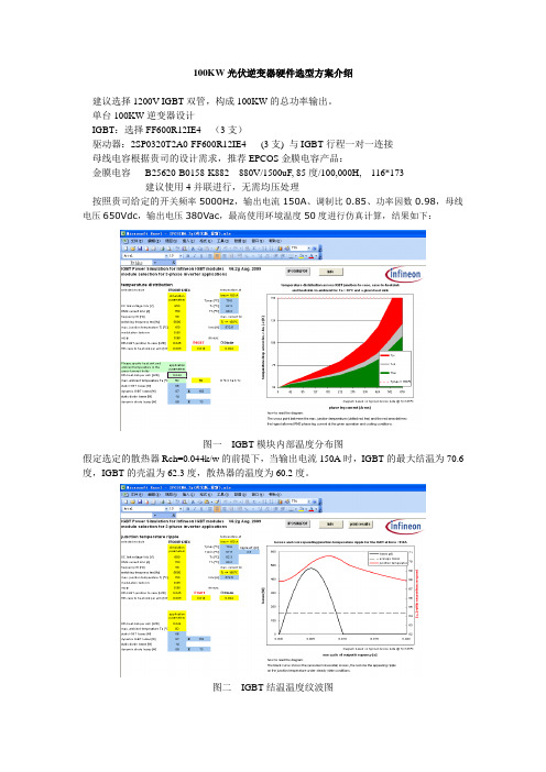
100KW光伏逆变器硬件选型方案介绍建议选择1200V IGBT双管,构成100KW的总功率输出。
单台100KW逆变器设计IGBT:选择FF600R12IE4 (3支)驱动器:2SP0320T2A0-FF600R12IE4 (3支) 与IGBT行程一对一连接母线电容根据贵司的设计需求,推荐EPCOS金膜电容产品:金膜电容B25620-B0158-K882 880V/1500uF, 85度/100,000H, 116*173建议使用4并联进行,无需均压处理按照贵司给定的开关频率5000Hz,输出电流150A、调制比0.85、功率因数0.98,母线电压650Vdc,输出电压380Vac,最高使用环境温度50度进行仿真计算,结果如下:图一IGBT模块内部温度分布图假定选定的散热器Rch=0.044k/w的前提下,当输出电流150A时,IGBT的最大结温为70.6度,IGBT的壳温为62.3度,散热器的温度为60.2度。
图二IGBT结温温度纹波图图二表明,在给定工作条件下,IGBT结温的最大结温,最小结温分别是70.6度和67.9度,温度纹波为2.8度。
图三IGBT损耗结果图三,表示IGBT模块在给定工作条件下,最终的损耗为:230.3W。
其中IGBT的通态损耗为66.1W,开关损耗为86.6W,反并联二极管的通态损耗为14.2W,开关损耗为59.3W,IGBT 内部焊线的损耗为4.22W。
因此,三相逆变器总的损耗P=6*230.3=1381.8W.在输出150A电流时,IGBT的最大结温小于150度,满足使用要求。
说明:实际上许多厂家的并网逆变器采用有并网变压器和无并网变压器并网两种模式,因为无变压器对的输出电压小,对逆变器输出电流的能力较强,因此,仅以无并网变压器为列,逆变器输出电压270V,经过三角转星型变压器转换成380V然后并网。
国家标准考虑的电网波动范围为(-10%~7%),最小持续时间10s,因此并网时候,需要考虑10%的过载情况。
GWV系列并网逆变器用户手册说明书
Dongguan Sheng Yang Industrial Co., Ltd.SY-GWV300/500W Grid Tie InverterUser ManualThis data is a copyright of DongguanShengYang Industrial Co.Ltd.Without the written permission of the copyright holder, any unit or individual shall not be duplicate, disclosed to others orused,or we will be held liable in liability. This guide and the latest information maybe have someerror, but we will improve on time. If no prior notice changes, but incorporated into the new usermanual, Dongguan Sheng Yang Industrial Co., Ltd. has the final say.Tel:+86-0769-********/85372132/85372133Fax:+86-0769-********/85099281Website:Address:NO.1Shang Xin Road, Xin Rong Cun, Xin’an Community,Chang’an Town,Dong Guan City,Guang Dong ProvinceProduct picturesSystem Function●Power line carrier-current communication(Follow-up perfect)By using electric power as a carrier of AC alternating current, can modulate high-frequency software-processa ble (60KHz) in AC wire transmission and can achieve the communication/ newsletter between inverters or between inverter and computer. And it can transfer the power data and the brightness date of the sunshine in the real-time. Also monitor all functions of inverter.1、Carrier frequency:60KHZ(Frequency customizable)2、Interface way:TTL level serial interface3、Carrier rate:300BPS4、Serial rate:9600BPS(Can customize according to customer's request)5、Modulation mode:FSK+DSSS6、Newsletter distance:2Km●Display function1、AC voltage display2、Outage display3、Power shows4、AC frequency display5、DC over-voltage display6、DC under- voltage display7、Power adjust display●12-grade power searchIn overcast weather,the solar battery’s output current is extremely tiny, then inverter will automatic open 12-grade power search function.1、The program can automatically open power adjustment for 12 times.2、The current direction can adjust from the maximum to the minimum.3、In automatic adjustment process, we will see the LOW light flashing.And the power will keep as a starting point,from 0 to the maximum output power, and it will restart at most for 12 times, then locked in the maximum power, the ST lamp long bright.4、It need 10 minutes for 12-grade power search.●Wide voltage input(15-60VDC)Achieve wide voltage input.1、DC voltage input:15-60VDC2、Second level power variable voltage conversion●High-frequency two-way and one-way grid function1、High frequency direct modulation, AC half wave synthesis2、Two-way grid means: Load consume directly. And can reverse AC current transmission.3、One-way grid means: Load consume directly. And banned reverse AC current transmission.●Kinds of frequency output function.It can apply to 50Hz and 60Hz frequency of AC.Frequency range: 45Hz ~ 63Hz●directly connected to the solar panels (do not need to connect the battery)Using precise Dynamic differential pressure type MPPT function, APL functions, the inverter automatically adjust the solar panels of maximum output power,simply connect the solar panel to the grid inverters. Do not need to connect the battery.1、Differential pressure type MPPT: 0.1 V accuracy2、Power lock: 10W (AC output)●AC 0 angle with high precision auto-detectionAC phase angle of 0 through isolation amplifier then input to the MCU for high-precision detection and analysis.The phase shift rate is less than 1%, thus achieve high-precision with phase modulation AC output together.1、AC phase shift: < 1%2、Over-zero protection: 0.2 V AC3、AC switching: 50Hz / 60HzSynchronous High-frequency ModulationIn the process of the grid, usually adapt the same phase angle in parallel. (ie, When the two-phase alternating current total is equal to e switch to combination the two AC fusion) and the product is rectified AC half-frequency AC to 100Hz first, then the machine use the high frequency current in the circuit and semi-100Hz frequency alternating current generated combination, to achieve high-frequency modulation.1、Modulation synthesis: half wave and full-bridge modulation synthesis (100Hz / 120Hz)2、Synthetic way: MOSFET full-bridge3、High frequency: 50KHzPure Sine Wave OutputUse SPWM directly to make pure sine wave output.1、Output waveform: Adopt complementary PWM to push-pull pure sine wave.2、Generate means: enhancement-mode SPWM●Automatic Sensing Function Solar LuminosityUse the latest luminosity perception operation technology. The different illuminate angle and intensity of the solar panel will produce different current output. Use advanced CPU to operate the different illuminance and the data can be directly displayed on the LCD. Then you can visually see the sense of the strength of the sun unit.Used more convenient.1、Luminosity sampling point :power sampling point2、High precision AD sampling: integral AD sampling methodPower Automatically Locked (APL)In different current fluctuations, we should use the MPPT function. When the MPPT function adjusted to the maximum power point, the product automatically powers locked in maximum power point, then made the output power more stable.1、Power lock: The biggest sampling point of MPPT.Automatically Adapt To Different Load Power FactorAdapt to any of the power load.●Constant Current, Constant PowerThis product is constant current, constant output power, without any overload, over-current phenomenon.●Automatically Shut Down When The Power Output Of a FaultWhen the city power system is in failure, the inverter will automatically turn off the output.Current Limit ProtectionCurrent limit●Stack Multiple Machines●Multiple small power inverters in parallel can achieve large output power.●High-Frequency High Conversion RateAdapt high frequency converter, the output more efficient.Maximum Power Point Tracking (MPPT)Because the current intensity and the voltage changes at any time, if there is no power point tracking, there will be a lot of problems. In the past time, usually adopt a solar controller, but this product uses high-precision MPPT operation power, automatic and immediate adjust the solar panels output power at the maximum output point, then achieve a stable output purposes.MPPT is for short of " Maximum Power Point Tracking". It means the controller can sense the voltage of the solar panels on time, and can track the highest voltage and current (VI).Then made the inverter discharge to power grid with the highest efficiency.The peak voltage (Vpp) of the solar panels is about 19.5V when it in factory. And the environment temperature is 25 ° C. The reason of setting this temperature(interestingly, different from the subjective imagination, we ordinary people the conclusion may let us surprised) is that when the weather is very hot, solar panels’ peak voltage will fall to about 17.5 V while in cold weather, the peak voltage can achieve 20.8 V.Now we back to contrast the difference of MPPT solar energy grid inverter and traditional inverter. The traditional solar inverter is a bit like the manual gearbox. When the engine speed increase, while the gearbox gear don't increase at the same time, it will definitely affect the speed of the car. For traditional inverter speaking, the parameter output power is been set in factory. It likes a car have been fixed set on fixed 1 gears, no matter how powerfully you trample accelerator, the speed of a car is limited. While have the MPPT function it will be different, it is automatically. It will automatically adjust the gears according to the engine’ speed, so it can make cars in the most gears in a reasonable efficiency standard operation. It means the MPPT controller can track the maximum power point of solar panels in real-time then express the biggest efficiency of solar panels. The higher the voltage, the more power can be output through the MPPT. Thus improve the charging efficiency.Theoretically speaking, using MPPT, the efficiency can be increased by 50% compared with the traditional inverter. But due to environmental impact and various around energy loss, the ultimate efficiency can improve20%-30% according to our actual testing.Parameter TableKD-WVC Grid-series models300Watt 500Watt Recommend use solar panels400Wp 600WpDC MAX input current 20A 40AAC MAX output power 300Watt 500WattDC MAX Open-circuit input-voltage 100VDCDC input voltage range 15~60VDCMAX output power factor 0.99DC input Reverse voltage protection FUSEAC output voltage range (120V versions:90~160VAC)(230V versions:190~260VAC)AC frequency range 45~63HzOutput current total harmonic distortion THDIAC <5%AC Phase <0.5%Islanding protection V AC;f ACOutput short circuit protection Current-limitingShow LED mode:power instruction;voltage instruction;AC frequency instruction;over-voltage instructionCommunication way 60KHz modulation,power line carrier-current communication Standby Power <1WNight Power <1WAmbient temperature range -25 ℃~60℃Humidity 0~99%(Indoor Type Design) Waterproof Indoor Type Design Electromagnetic Compatibility EN50081.part1 EN50082.part1 Power System Disturbance EN61000-3-2 EN62109 Network test DIN VDE 1026 Certificate CEPacking and weightNet weight 1.3kg(200—600W) 2.0kg(800—1000W) G weight 2.0kg(200—600W) 2.7kg(800—1000W) Size (L x W x H) 21 x 16.5 x5.3cm 31 x 16.5 x5.5cmPackage (L x W x H) Inner box:34x25x15.5CMBig box:51x37x33CMInner box :43x25x15.5CBig box:52x45x33CMInstallation Wall hanging AC power cord length 1.8m Cooling FanUser Guide1、Installation Connection1、Red terminal: Connect DC positive, black terminal: Connect DC negative. Show in Figure 1.Figure 12、AC socket: Connect to the mains. Put the side of the AC cord which has holes into the inverter with 3 footoutlet and the other side of the AC cord to home 3PIN AC outlet. Show in Figure 2.Figure 2 Figure 33、Switch: Connect the connections in right way, then turn on the switch. The inverter starts to work.2、Grid tied inverter used in the wind and solar street lights.Use this product, do not need to add solar panel controller, battery.Connection Method 1 (Figure 4 below): Connection method 2 (Figure 5 below): Figure 4 Figure 5Connection Method 1: Wind energy, solar energy can supply to the grid at the same time, then achieve the highest efficiency. First consider this connection method. Figure 5Connection method 2: Use a large power generation capacity first. The other capacity is in added. Wind and solar capacity complement each other with moderate efficiency.3、Stack usingIn order to achieve higher power use requirements, this product can be stacked, such as: 4 grid inverter1000W stacking can achieve 4000W.And the number of the stacking is unlimited. Used as shown in Figure 6:Figure 64、Input and output1、DC input limit✧Input voltage range: 14V to 60VSolar Panel: Recommend using the power more than 30W and the standard voltage of 36V PV panels.Recommend using multiple solar panels. Solar panel in series will result in high-input voltage which will exceed the working voltage range of the inverter.Wind turbine system: Rated voltage 24VDC, maximum voltage 48VDC.2、AC output:✧V oltage range of the inverter whose output is 220V AC.: 170V - 260V,50HZ✧V oltage range of the inverter whose output is 110V AC.: 90V - 160V,60HZ5、LED Indicator:1、Red LED:1、Low-voltage protection (input DC voltage is less than 14VDC).2、Over-voltage protection (Input DC voltage is greater than 60VDC).3、Over-temperature protection (when the chassis temperature is above 75℃,the temperature dropped about 2-10 minutes to restart automatically after cooling).4、Fault Protection (when 110V AC or 220V AC power outage or shutdown).5、Islanding protection: When the electric supply stop, the inverter automatically shut down output.2、Green LED:1、Green LED flashing: The inverter is adjusting power output. MPPT is in working condition.2、Green LED long in time: The inverter is in working condition with the maximum output power. Notes---Non-professionals do not disassemble. Only qualified personnel may repair this product.---Please install inverter in the low humidity and well-ventilated place to avoid the inverter over-heating, and clear around the inflammable and explosive materials.---When using this product, avoid children touching, playing, to avoid electric shock.---Recommended Maximum DC input 4AWG cable capable of handling more than 50A of the cable size.---Optimal length of the DC input line 8M or less, long cable will allow solar panels to the inverterDC voltage drop caused by wear and tear.---Connected to a power outlet to provide AC.---Connected solar panels, battery or wind generators DC input DC power supply cable. ---Proposed wind power plant with its own charge controller and load dump. Accessories for productOne standard AC wireOne warranty cardOne user manualOne certificate of quality。
光伏并网逆变器选型指南

2.控制部分是采用高速度的微处理器为核心的控制部件,所以具有了输出过载,输出高、低电压保护动作快,抗干扰能力强,稳压精度高等特性。
E:附加功能,人性化设计
人性化界面设计
数据显示多样化
方便的窗口排列设置
避免重复运行的设计
多种时间日期显示
F:不断创新,力求完美(无线监控介绍)
系统描述:
设备只需插入一张SIM卡,就可通过GSM网络以短消息或数传(Data)的形式完成远程的双向数据传输。而远程终端可以是PC机,移动手机或其他移动设备。
4.1.1LED指示灯说明
LED 灯
含义
并网
并网工作(并网发电,灯亮)
离网
停止并网(离网,灯亮)
4.1.2按键说明
1)监控系统单元共设有五个按键,功能名称按顺序分别为:返回键(ESC)、上翻键( ),下翻键( ) 、确认键(read)、复位键(Reset)。
2)液晶显示菜单中的一级菜单包括:系统设置、实时时钟、实时监控、故障记录。
1、1MW以上光伏发电的系统:建议选择多台GSG250KC的电源进行并联运行;
2、500KW至1MW的系统:建议选择多台GSG100KC的电源进行并联运行;
3、200KW至500KW的光伏发电系统:建议选择多台GSG50KC的并联运行;
4、200KW以下的光伏发电系统:建议采用多台GSG20KC或GSG50KC的电源进行并联运行。
具体功能
A:实时数据显示与处理
采用召唤应答式规约,在线实现数据实时显示。
对于实时数据处理后,可以参照对比专家系统意见,提供最佳电源使用优化方案。
某公司500KW逆变器技术升级
某公司500KW逆变器技术升级作者:王凯刘加勇顾莹莹来源:《科学与财富》2018年第32期摘要:该品牌光伏并网逆变器采用九折型材结构,不同发热源之间无遮挡,存在明显热串扰问题,严重影响关键元器件的寿命;逆变核心单元使用电解电容,寿命相对较短,且受温度影响非常大;交流接发触器由外部供电直接控制,吸合时的过电流极易冲坏IGBT;交流风机使用外部供电直接控制,长期运行,造成资源浪费。
关键词:升级;电气图纸;控制系统;功率单元;散热系统;经济效益一、光伏并网逆变器简介逆变器是一种由半导体器件组成的电力调整装置,主要用于把直流电力转换成交流电力,一般由升压回路和逆变桥式回路构成。
升压回路把太阳电池的直流电压升压到逆变器输出控制所需的直流电压;逆变桥式回路则把升压后的直流电压等价地转换成常用频率的交流电压。
随着行业不断发展,各个逆变器厂商难免会遭受行业的多次洗牌,稍有不慎就会被淘汰,本文所述厂家就是其中的典型代表,企业被洗牌,光伏电站内的逆变器处于无售后服务状态,导致大量经济损失,本文所述技术升级方案则可以完美解决此类问题。
二、方案综述1升级前逆变器概述该品牌光伏并网逆变器采用九折型材结构,不同发热源之间无遮挡,存在明显热串扰问题,严重影响关键元器件的寿命;逆变核心单元使用电解电容,寿命相对较短,且受温度影响非常大;交流接发触器由外部供电直接控制,吸合时的过电流极易冲坏IGBT;交流风机使用外部供电直接控制,长期运行,造成资源浪费。
2升级后逆变器概述升级方案主要包括2部分:外部升级、内部升级。
(1)外部升级:前后门板增开进风口,安装百叶窗;(2)内部升级:拆除原有机器的逆变单元、供电系统、控制系统等,调整横梁位置,安装升级后的部件。
三.控制系统及模块化功率单元升级1 控制系统升级1.1单核控制系统为通用双核DSP处理器该品牌500KW逆变器控制系统采用单核控制系统,与升级后的双核冗余DSP控制系统相比,单核控制系统控制速度较慢,效率较低;升级后,控制系统采用自主知识产权的双DSP 控制,各司其职,高效可靠,其包括主控板、AD采样板、IO控制板;1.2控制系统软件升级1)LVRT功能:该品牌型逆变器在升级系统软件后满足国家电网公司企业最新标准GB/T19964-2012《光伏电站接入电网技术规定》中要求的光伏电站低电压穿越功能。
500KW生物质能发电并网系统设计及配置

500KW生物质能发电并网系统设计及配置本文档介绍了500KW生物质能发电并网系统的设计和配置。
以下是系统设计的几个关键方面:系统容量和组件选择500KW生物质能发电并网系统需要选择适当的组件来实现高效的发电。
在选择发电机组和逆变器时,应考虑系统容量、负载需求和逆变效率等因素。
发电机组配置对于500KW系统,我们建议采用多个小型生物质发电机组并联的方式。
这样可以提高系统的可靠性和灵活性,并减少单个发电机组故障对系统运行的影响。
电网连接生物质能发电系统需要与电网进行连接,以便将发电的电能注入到电网中。
电网连接的过程需要符合当地的法规和技术要求。
确保系统的安全性和稳定性是非常重要的。
逆变器选型和配置逆变器是将发电机产生的直流电转换为交流电的关键组件。
在选型时,应考虑逆变效率、功率因数调节、抗干扰能力等因素。
逆变器的配置与并网逆变器和离网逆变器有所不同,需要根据实际情况进行调整。
控制系统设计控制系统对整个500KW生物质能发电并网系统的运行起着重要作用。
控制系统需要能够实时监测发电机组的运行状态,并对逆变器的工作进行调节和保护。
控制系统的设计应遵循可靠性和安全性原则。
安全与维护对500KW生物质能发电并网系统的安全性和维护进行有效管理至关重要。
定期检查发电机组和逆变器的状态,进行预防性维护和故障排除。
确保发电系统的安全运行。
总结500KW生物质能发电并网系统的设计和配置需要综合考虑多个因素,包括系统容量、组件选择、电网连接、逆变器选型和配置、控制系统设计、安全与维护等。
在设计过程中,要遵循简单策略和法律要求,确保系统的高效运行和安全性。
光伏并网逆变器的设计
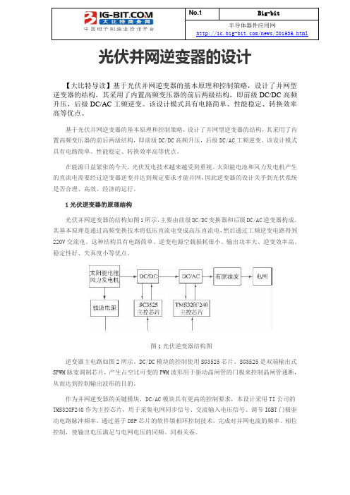
半导体器件应用网/news/201535.html 光伏并网逆变器的设计【大比特导读】基于光伏并网逆变器的基本原理和控制策略,设计了并网型逆变器的结构,其采用了内置高频变压器的前后两级结构,即前级DC/DC高频升压,后级DC/AC工频逆变。
该设计模式具有电路简单、性能稳定、转换效率高等优点。
基于光伏并网逆变器的基本原理和控制策略,设计了并网型逆变器的结构,其采用了内置高频变压器的前后两级结构,即前级DC/DC高频升压,后级DC/AC工频逆变。
该设计模式具有电路简单、性能稳定、转换效率高等优点。
在能源日益紧张的今天,光伏发电技术越来越受到重视。
太阳能电池和风力发电机产生的直流电需要经过逆变器逆变并达到规定要求才能并网,因此逆变器的设计关乎到光伏系统是否合理、高效、经济的运行。
1光伏逆变器的原理结构光伏并网逆变器的结构如图1所示,主要由前级DC/DC变换器和后级DC/AC逆变器构成。
其基本原理是通过高频变换技术将低压直流电变成高压直流电,然后通过工频逆变电路得到220V交流电。
这种结构具有电路简单、逆变电源空载损耗很小、输出功率大、逆变效率高、稳定性好、失真度小等优点。
图1光伏逆变器结构图逆变器主电路如图2所示。
DC/DC模块的控制使用SG3525芯片。
SG3525是双端输出式SPWM脉宽调制芯片,产生占空比可变的PWM波形用于驱动晶闸管的门极来控制晶闸管通断,从而达到控制输出波形的目的。
作为并网逆变器的关键模块,DC/AC模块具有更高的控制要求,本设计采用TI公司的TMS320F240作为主控芯片,用于采集电网同步信号、交流输入电压信号、调节IGBT门极驱动电路脉冲频率,通过基于DSP芯片的软件锁相环控制技术,完成对并网电流的频率、相位控制,使输出电压满足与电网电压的同频、同相关系。
滤波采用二阶带通滤波器,是有源滤波器的一种,用于传输有用频段的信号,抑制或衰减无用频段的信号。
其可以有效地滤除逆变后产生的高频干扰波形,使逆变后的电压波形达到并网的要求。
并网光伏电站设计—逆变器

b、光伏阵列中某一个组件被阴影遮挡时,该组件不仅不能 输出功率,还会成为系统的负载,引起该组件的发热。
2、组串型逆变器
(1)特点:每个光伏组串通一个逆变器, 在直流端具有最大功率峰值跟踪,在交流 端并联并网。对光伏组件串的利用率高一 些。
c、电压保护水平(Vp):
汇流箱参数:额定直流电 电压保护水平Vp/kV
压Vn/V
Vn≤60
<1.1
60<Vn≤250
<1.5
250<Vn≤400
<2.5
400<Vn≤690
<3.0
690<Vn≤1000
<4.0
5、其他功能
(1)通信功能,实现远程通信; (2)显示功能,具有显示光伏组串电流; (3)外壳防护等级,IP65,满足室外安装。
2、选择逆变器类型
(1)大型电站(100kW以上的)一般选择 集中型逆变器;
(2)家庭电站或某些单位的小型电站一般 选用组串型逆变器;
(3)微型逆变器由于价格较高,目前国内 很少使用。
3、逆变器功率的选择
要与光伏方阵的设计容量相匹配,差距不 要太大。
六、汇流箱
汇流箱是将光伏组串连接,实现光伏组串 间并联的装置,并将必要的保护器件安装 在此装置内。
并网光伏电站设计—选型
光伏发电系统组成 主要包括太阳能电池组件、光伏支架、
汇流箱、逆变器、升压变压器、二次监控系 统等。
光伏并网逆变系统的设计
一、光伏并网逆变器的类型 二、光伏并网逆变器的功能 三、光伏并网逆变器电路结构框图 四、阳光电源公司SG500MX的交流参数 五、逆变器选型 六、ห้องสมุดไป่ตู้流箱
- 1、下载文档前请自行甄别文档内容的完整性,平台不提供额外的编辑、内容补充、找答案等附加服务。
- 2、"仅部分预览"的文档,不可在线预览部分如存在完整性等问题,可反馈申请退款(可完整预览的文档不适用该条件!)。
- 3、如文档侵犯您的权益,请联系客服反馈,我们会尽快为您处理(人工客服工作时间:9:00-18:30)。
500W光伏并网逆变器设计
1 引言
太阳能的大规模应用将是21世纪人类社会进步的重要标志,而光伏并网发电系统是光伏系统的发展趋势。
光伏并网发电系统的最大优点是不用蓄电池储能,因而节省了投资,系统简化且易于维护。
这类光伏并网发电系统主要用于调峰光伏电站和屋顶光伏系统。
目前,美、日、欧盟等发达国家都推出了相应的屋顶光伏计划,日本提出到2010年要累计安装总容量达50000MW的家用光伏发电站。
作为屋顶光伏系统的核心,并网逆变器的开发越来越受到产业界的关注[1]。
2 光伏并网系统设计
2.1 系统结构
光伏并网逆变器的结构如图1所示。
光伏并网逆变器主要由二部分组成:前级DC-DC
变换器和后级DC-AC逆变器。
这2部分通过DClink相连接,DClink的电压为400V。
在本系统中,太阳能电池板输出的额定直流电压为100V~170V。
DC—DC变换器采用boost 结构,DC—AC部分采用全桥逆变器,控制电路的核心是TMS320F240型DSP。
其中DC-DC 变换器完成最大功率跟踪控制(MPPT)功能,DC-AC逆变器维持DClink中间电压稳定并将电能转换成220V/50Hz的正弦交流电。
系统保证并网逆变器输出的正弦电流与电网的相电压同频和同相。
2.2 控制电路设计
2.2.1 TMS320F240控制板
TMS320F240控制板如图2所示,以TI公司的TMS320F240型DSP为核心,外围辅以模拟信号调理电路、CPLD、数码管及DA显示、通信及串行E2PROM,完成电压和电流信号的采样、PWM脉冲的产生、与上位机的通信和故障保护等功能。
2.2.2 电压和电流信号检测电路
模拟信号检测电路的功能是把强电信号转换为DSP可以读取的弱电数字信号,同时要保证强电和弱电的隔离。
笔者选用惠普公司的HCPL7800A型光电耦合器,其非线性度为0.004%,共模电压为l 000V时的共模抑制能力为15kV/lμs,增益温漂为0.000 25V /℃,带宽为100kHz。
具体隔离检测电路如图3所示。
2.2.3 IGBT驱动电路
DSP控制电路产生的PWM信号先通过驱动电路,然后控制IGBT开关管的开通状态。
笔者选用惠普公司的HCPL3120型专用IGBT驱动电路,如图4所示。
驱动电路的输入和输出是相互隔离的,驱动电路还有电平转换功能,将DSP的+5V控制电压转换为+15V的IGBT驱动电压,驱动电路电源采用金升阳公司的B0515型隔离电源模块。
2.2.4 辅助电源
为了给光伏并网逆变器的控制电路、信号采集电路及开关管驱动电路等提供各种工作电源,需要设计1个与主电路隔离的辅助电源。
辅助电源的输入电压为100VDC~170VDC;输出的3路电压分别为+15VDC(2.5W)、-15VDC(2.5W)和+5VDC(5W);输出电压波动小于1%。
笔者采用最新的Topswitch系列FOP222型电路进行辅助电源的设计[3]。
辅助电
源主电路采用单端反激式拓扑结构,如图5所示。
3 最大功率跟踪控制MPPT
MPPT的实质是一种自寻优过程[4],常用的方法有固定电压跟踪法、扰动观测法、导纳微增法和间歇扫描跟踪法。
笔者采用的是间歇扫描跟踪法。
其核心思想是定时扫描一段(一般为0.5倍~0.9倍的开路电压1阵列电压,同时记录不同电压下对应的阵列输出功率值,然后比较不同点太阳电池阵列的输出功率,得出最大功率点。
笔者对间歇扫描法进行了改进,即在较短时间间隔内只在缩小的跟踪范围内(Vm-0.1Voc和Vm+0.1Voc)扫描1次。
其中Vm和Voc分别是太阳能电池阵列的最大功率点工作电压和阵列开路电压。
每隔一段较长时间后再在整个跟踪范围内对各工作点扫描1次。
改进后的间歇扫描法控制既保持了跟踪的控制精度又提高了系统运行的稳定性。
4 反孤岛效应控制方法
孤岛效应是指由于电气故障、误操作或自然因素等原因造成电网中断供电时各个用户端的太阳能光伏并网逆变器仍独立运行的现象。
一般来说,孤岛效应可能对整个配电系统
设备及用户的设备造成不利的影响,包括并网逆变器持续供电可能危机电网线路维护人员的生命安全:干扰电网的正常合闸过程:电网不能控制孤岛中的电压和频率。
可能造成用户用电设备的损坏[5]。
因此解决光伏并网系统的孤岛问题显得尤为重要。
笔者提出了一种正反馈频率扰动的反孤岛检测方法。
该方法的主要思想是首先判断当前电网电压频率的漂移方向,然后周期性地对输出电流频率施以相应的扰动。
同时观测实际输出电流频率。
当输出电流频率跟随扰动信号变化即输出电流频率可由并网逆变器控制时,就成倍增加扰动量。
以达到使输出电流频率快速变化而触发反孤岛频率检测的目的。
5 实验
笔者对500W光伏并网逆变器进行了测试。
采用8块额定功率为50W的多晶硅太阳电池阵列串连,输入电压为100VDC-170VDC,输出电压为220VAC,输出频率为50Hz。
输入侧分别用安培表和伏特表测量太阳电池的输入电压和电流,输出侧采用FLUKE 43B型电能质量分析仪检测并网逆变器输出交流电压和电流的参数和波形。
由于输出交流电流值太小,因此采用在电流探头上绕8匝后测量。
测试结果是太阳电池的输出电压基本在122V左右,输出电流为2A,输出功率为244W。
由测试结果可以看出。
逆变器的输出电压为230.9V,输出功率为1.45kW/8=181.2W,所以逆变器的效率为0.74,逆变器的效率包括DC-DC变换和DC-AC变换及辅助电源的总效率。
逆变器输出功率因数为0.97,基本保持与网压同频和同相。
输出电流的基波分量占电流总量的99.6%,输出的电能质量是令人满意的。
6 结束语
由实验波形可以看出,所设计的光伏并网逆变器工作稳定。
性能良好。
由于采用了以TMS320F240型:DSP为主的控制电路,系统具有较好的动态响应特性。
采用了具有最大功率跟踪和反孤岛控制功能的软件设计,因而能充分利用太阳能电池的能源且能检测孤岛效应的发生。