CHY100_datasheet
IC datasheet pdf-REF1004,pdf(Micropower Voltage Reference)

The REF1004 is offered in an 8-lead Plastic SOIC package and shipped in anti-static rails or tape and reel.
Typical Operating Circuit
NC 1 NC 2 NC 3 Anode 4
IR = 100µA
10Hz ≤ IR ≤ 10kHz
60
120
µV
LONG TERM STABILITY
IR = 100µA
TA = 25°C ± 0.1°C
20
2 (1) This specification applies over the full operating temperature range of 0°C ≤ TA ≤ 70°C. (2) This specification applies over the full operating temperature range of 40°C ≤ TA ≤ +85°C. (3) Denotes the specifications which apply over the full operating temperature range.
CPSC-CH-E1001-08
美国·消费品安全委员会·实验室科学理事会·化学分部马里兰州Gaithersburg城Darnestown路10901号,邮编:20878测试方法:CPSC-CH-E1001-08[技术翻译:piery2006 校对:林雪霞]测定儿童金属产品(包括金属首饰)中总铅(Pb)含量的标准作业程序2008年12月4日本文件提供了美国消费品安全委员会(CPSC)测试实验室(LSC)分析儿童金属制品中的铅(Pb)含量所使用的测试方法的相关信息。
所述的方法为测定金属物品(例如:儿童金属首饰,但不局限于此)中的总铅含量。
CPSC工作人员认为此测试方法能够满足大多数测定消费品的金属和合金零部件中铅含量的要求。
对于某些特殊合金产品,需要以相关化学知识、材料科学和合金基质所适用的酸为基础,对方法进行调整。
所选择的测试方法应可以将被分析的样品材料完全消解。
如果与方法规定的适用范围不相符合,或是样品材料不能达到高效、高性能的完全消解,最好不要使用这些测试方法。
本文法适用于金属和金属合金零部件,CPSC工作人员并不建议使用到其它材料上。
因为在下述条件下,材料可能不会溶解,或是当样品与规定的酸混合时,造成与材料不适当的混合,与安全实验室操作不相符。
一般做法是将样品的可接触零部件磨成粉末。
然后在浓硝酸与浓盐酸的混合酸中完全溶解,最后采用电感受耦合等离子体原子发射光谱法(ICP-OES)分析。
其它分析方法如:电感耦合等离子体质谱法(ICP-MS)、火焰原子吸收光谱法(FLAA)、石墨炉原子吸收光谱法(GFAA)在合适的条件下,可以作为ICP-OES法的替代方法使用。
当使用替代分析方法时,应采用合适的、公认的分析技术(标准)。
定义:1. 样品―待测试的单个消费品或同一批次中一组相同的消费品。
2. 零部件―整个样品上的一个单独的次级单元。
例:一个手镯可以被分解成珠子、钩子和悬饰等数个零部件,每个零部件应单独分析。
Keithley 200 100 MHz 混合域波形展示仪数据表说明书

One Oscilloscope ,Two Domains
RSMDO-2000E series is multi-functional mixed domain oscilloscope. The series includes two feature combinations : RSMDO-2000EG and RSMDO-2000EX. MDO-2000EG models have a built-in spectrum analyzer and a dual channel 25MHz arbitrary waveform generator and RSMDO-2000EX models feature a built-in a spectrum analyzer, arbitrary waveform generator, a 5,000 count DMM, and a 5V/1A power supply. The first of its kind, RSMDO-2000EX is the only oscilloscope to equip with a DMM and a power supply in the T&M industry.
hitrol co., ltd. - ht(hpc)-100ct series - instruct

HITROL CO., LTD.HEAD OFFICE.FACTORY.R&D INSTITUDEHITROL CO.,LTD. 141, Palhakgol-gil, Jori-eupPaju-si, Gyeonggi-do, KoreaTEL. : (00)-82-31-950-9700FAX. : (00)-82-31-943-5600INSTRUCTION MANUALCAPACITANCE TYPE LEVEL TRANSMITTERHT-100CT SeriesHPC-100CT SeriesTable of contentsNonconductive TIntroductionCharacteristicsOperation Principle■ Excellent degree of precision■ Semipermanent solid structure with no mechanical driving part■ Various probe forms according to the purpose of use■ Effortless installation of wire forms (HT-100CTW-2); easily used for corrosive liquid (solution) ■ Interface between water and oil can be measured.■ Explosionproof enclosure available (Ex d IIC T6/T4); (HPC-100CT-2 Series)The HT(HPC)-100CT-2 Series is a water level transmitter that continuously measures the change of tank level using the permittivity of the liquid. It can be easily installed and calibrated and can simply be used even for corrosive liquid. The HT(HPC)-100CT-2 Seriesis generally used to measure the liquid in various areas such as pure water, industrial water, oil tanks, and chemical tanks.When the level between the electrode probe and electrode wall increases, the air around the electrode probe is replaced by other dielectric substances (measured object), and the value of the electrostatic capacity changes according to the level. The electrode probe has the initial low value of electrostatic capacity when it is in the air, but the value of the electrostatic capacity increases if the measured object increases and covers the electrode probe. If there are two insulated conductors, the electrostatic capacity is decided by the size of the two conductors, relative location, and the permittivity of the medium (contents) existing in thetwoconductors.The following formula shows the change of the electrostatic capacity (ΔC) when a substance with ε₂ permittivity is filled to l level if the air permittivity is ε₁ between the two conductors on a concentric circle.ΔC =Here,log D/d10(ε₂ ε₁X l- )is constant as initial conditions. Thus, if you regard it as Constant K, ΔC is decided only by l, the height of the substance you want to measure. Therefore, if you measure ΔC,you can identify the current position of Level.log D/d10(ε₂ ε₁X l- )[pF]SpecificationsWeather-Proof VersionModel HT-100CT HT-100CTH HT-100CTW HT-100CTWHProbe Type Rod WireMounting Screw & FlangeAmbient Temperature -20°C ~ +60°CProcess Temperature -40°C~+80℃ -40°C~+150℃ -40°C~+80℃ -40°C~+150℃Process Pressure Vacuum~ 20kg/cm2(300#)Combination Unit HLC-100C-PSignal Transmission ANALOGUE 3-WIREEnclosure Weather-Proof (IP65)Wetted Parts Material SUS 304, 316L with TEFLONProcess Connection PT 1”(M) Screw 50A JIS 10K RF FLANGEHousing ; Cable Entry AL. ; PF 3/4”(F)Accuracy ±0.5% F.SEx-Proof VersionModel HPC-100CT HPC-100CTH HPC-100CTW HPC-100CTWHProbe Type Rod WireMounting Screw & FlangeAmbient Temperature -20°C ~ +60°CProcess Temperature -40°C~+80℃ -40°C~+150℃ -40°C~+80℃ -40°C~+150℃Process Pressure Vacuum~ 20kg/cm2(300#)Combination Unit HLC-100C-PSignal Transmission ANALOGUE 3-WIREEnclosure Ex-Proof (Ex d IIC T6, IP65)Ex-Proof (Ex d IIC T4, IP65)Ex-Proof (Ex d IIC T6, IP65)Ex-Proof (Ex d IIC T4, IP65)Wetted Parts Material SUS 304, 316L with TEFLONProcess Connection PT 1”(M) Screw 50A JIS 10K RF FLANGEHousing ; Cable Entry AL. ; PF 3/4”(F)Accuracy ±0.5% F.SProduct Composition and Technical DataThe dimensions on the following pages are indicated in mm Probematerial:304,316LwithTEFLONRod Probe Rod Probewith Ground rod Rod Probewith Ground tubeWire ProbeWire Probewith Ground WireWire material :316L withTEFLONGround tubematerial :304,316LGround rod material : 304,316L with TEFLON Weightmaterial :304,316L,TEFLONWire material :316L withTEFLONWeightmaterial :304,316L,TEFLONDielectric Constant ValueFuel Oil : Gasoline,Diesel… 2 Hydrogen chloride 4.6~12 Hexane, Liquid 6 Butanol 17~18 Ammonia 16~25 Alcohol 16~31 Acetone 20 Caustic soda 22~26 Ethanol 25 Methano 32~33 Glycerin 47~68 Water 81 Sulfuric acid84Information about the relative dielectric constant can be downloaded from our website by accessing the Knowledge Base .Rod ProbeRod Probe with Ground rodRod Probewith Ground tubeWire ProbeWire ProbeWith GroundWireTotal length(L) 100~3,000 100~3,000 100~3,000 1,000~15,0001,000~15,000Probe dia.(including TEFLON)Ф15Ф15 Ф15Ф2.5Ф2.5 Ground dia. - Ф8(including TEFLON)Ф27.2 - Ф2.5(including TEFLON)For acid liquids OO-OOFor high-viscosity liquids O O - - - For non_ metal tanks - O O - O For sphere tanks-OO-OInstallation and PrecautionsMax.300(b)(d) (e) (f)(c)The electrostatic capacity–type level gauge can be installed in screw (PT, NPT, PF) and flange (ANSI, JIS, DIN) as well as tri-clamp and other various locations. Pay attention to the following matters during installation;■ Never install the probe in a place where the measured object flows in. (a) ■ If the fluidity exists in the contents of the wire probe, install the guide tube. (d)■ Install the probe within max. 300 mm from the tank wall, (b) and if the installation distance is far from the tank wall, install it in the ground tube type (e).■ If the probe is long or its contents have fluidity, install a fixing bracket completely insulated from the sensing probe at the lower part of the probe. (c)■ If the tank material is nonconductive (ex. FRP), use the probe with the ground tube (e) (d), and if the measured object is a corrosive chemical substance, use the probe with the ground rod (f).■ If the tank has a mixer, install the probe at a safe distance from the mixer. ■ If the tank wall has a structure (ex. angle), use the probe with the ground tube (e)■ If the concrete tank or the installation place is a nonconductive structure, use the probewith the ground tube. (g)■ If the tank structure is a sphere tank type, use the probe with the ground tube. (h) ■ If the probe is installed at the tank side, install the chamber. (i) ■ The ground tube should have ventholes at proper places. (j)(g)(h)(i)Conductive T anks (Metal Tanks)When installing the probe in a conductive tank, the transmitter housing and tank should be grounded like in the figure below.Nonconductive Tanks (Nonmetal tanks)When installing the probe in a nonconductive tank, the ground tube (rod) or ground wire should be used and grounded with a transmitter housing like in the figure below.Wire Connection and AMP Composition→ This product is a separation type.해당 제품은 분리형이며, Refer to the left figure for the wire connection between the sensor(HT(HPC)-100CT) and the control unit (HLC-100C-P).└> The above figure shows the HLC-100C-P Terminal block.1, 2, 3: AC power terminal8, 9: DC 4–20 mA output terminal14, 15, 16: Sensor connection terminalAdjustment MethodZERO Adjust[1] Connect the DC 4–20 mA indicator.[2] While watching the connected indicator, turn Zero Range ADJ.(①) to the clockwise direction, and set it at near 0%.[3] Set it at accurate 0% using Zero Fine ADJ. (②) for fineadjustment.SPAN Adjust[1] While watching the indicator after completely filling the contentsin the container, turn ON/OFF the Full Range ADJ. (③) in the order of6->5->4->3->2->1, and adjust it until the indicator points near100%.[2] Set it at accurate 0% using Full Range ADJ. (④) for fineadjustment.(Span adjustment range: 40–4,000pF)HITROL CO., LTD. 11Precautions in InstallationPrecautions in SeparationOutside WireEntry Method andPrecautions(ExplosionproofProduct)Precautions in Ground Connection(ExplosionproofProduct)Safety and Environment■ Check the tank level and presence of the measured object before separation. ■ The product can overheat and cause burns. Thus, use of gloves, etc., is necessary in separation. ■ Do not open the product cover if explosive gas seems to be present around the product. ■ For an explosionproof product, open the cover after dismantling the set screw (explosionproof key). ■ Carry out the dismantling work in the power OFF state. ■ When opening/closing the product cover, pay attention not to damage the O-ring or gasket. ■ Precautions during transportation and assembling When fastening a product to a container, be sure to use tools to achieve maximumadhesion.Do not lose the lock during use, and make sure it is always fastened. Do not apply impact to the product.■ The same size should be used in flange or screw fastening. ■ The user should fasten the washer between the bolt and nut to prevent loosening. ■ Gasket should be used when fastening the flange. (Select the gasket in consideration of the contents temperature and container pressure.) ■ The user should install the proper product after deciding whether the area is explosion district. ■ Supply the power after the installation is complete and the product cover has been assembled. Never apply impact to the product while being transported.■ The user should use the cable grand connection method or metal tube entry method at the wire entrance. In addition, when the user connects the wire using the outside wire entry method, he/she should use an explosion proof certified product with performance that is equivalent to or higher than the relevant explosion proof product. ■ For the outside wire entrance that is not in use, use the clogging plug that passed the safety test with performance that is equivalent to or higher than the relevant explosion proof product.■ The grounding includes outside grounding and inside grounding. For outside groundconnection, the grounding wire size should be 4 ㎟ (4 mmSQ). ■ The inside grounding wire should have the same size as the power line, and the size of the inside grounding terminal lug should be 3.1 ㎟ (3.1 mmSQ). If the power line is longer than 3.1 ㎟, connect the grounding wire after pulling out the terminal lug. Be sure to use a washer when connecting the inside ground terminal after pulling out the terminal lug.HITROL CO., LTD. 12Product LabelingUser Education■ Product LabelThe product label is attached to the housing, and it indicates the model name, serial number, service temperature, service pressure, and output. The serial nu mber is a unique manufacture number that distinguishes the product. Never apply general non -explosion proof pro aducts to an explosion district. The user should be fully aware of the matters described above , and the fluid temperature in the product container should not exceed max. +80℃ for the general type and max. +150℃ for the high -temperature type. In addition, the temperature around the housing should not exceed −20℃ to +60℃. (The explosion proof product is an internal pressure explosion proof product. Therefore, never open the product cover during use.) The exp losion proof product was designed according to Article 34 of the Occupational Safety and Health Act, and Article 58 of its Enforcement Ordinances. ■ Product Disposal When disposing of a product because it is no longer appropriate for use, separate the AMP in the product housing and body part. There is no need to pay special attention because there are no components affecting the environment (ex. mercury switch). <Weather - Proof > <Ex-Proof >Failure Check andRepair/ MaintenanceWarranty and ContactWarranty and ServiceThe warranty period for this product is 2 years after the shipment, and the consumer can receive free after-sales (A/S) service if the failure occurred in normal use. Service requests other than the product failure A/S service may incur service charges regardless of warranty.Contact our home page or head office for A/S requests.Telephone Number of Head Office, Factory, and Research CenterAddress: HITROL CO., LTD, 141, Palhakgol-gil, Jori-eup, Paju-si, Gyeonggi-do, KoreaTel.: 031-950-9700 (Head Office and A/S)Fax: 031-943-5600 (Head Office and A/S)■ Product TestThe major checking part for the electrostatic capacity–type level transmitter includes the sensor part and the transmission part.The life span of the major parts varies according to user environment, and they can be used in optimum condition through periodic checking. Therefore, the user should conduct periodic checking at least once a year for repair and maintenance. Carry out a visual inspection on the damage, etc., on the product, and periodically remove foreign substances attached to the probe as these can degrade accuracy. When removing the foreign substances, be careful not to damage the Teflon part.■ Failure CheckThe level of measured object changes, but the output does not change.▶ Insufficient power supply▶ Wrong adjustment of ZERO and SPANOnly a slight change of output to the change of level of measured object▶ Wrong adjustment of ZERO and SPAN▶ Slight change of probe ΔC valueNo change of level, but output fluctuation is present▶ Wrong grounding▶ Noise on the lines▶ Extreme fluctuation of measuring device▶ Bad insulation of probeOutput indicates Full (20 mA) of higher regardless of the change of level of the measured object.▶ Wrong adjustment of ZERO and SPANNever separate the cover in an environment exposed to explosive gas.HITROL CO., LTD. 13。
HACH SC100控制器 说明书

货号 58600-18 Hach sc100™控制器用户手册2005 年 2 月,第5版版权所有 © 2004–2005,美国哈希公司。
印刷地:美国请访问 目录第 1 章规格 (5)第 2 章基本信息 (7)2.1 安全信息 (7)2.1.1 危险指示信息说明 (7)2.1.2 安全标签 (7)2.2 一般产品信息 (7)第 3 章安装 (9)3.1 机械安装 (11)3.1.1 控制器尺寸图解 (11)3.1.2 安装控制器 (13)3.2 线路安全信息 (15)3.2.1 静电释放 (ESD) 考虑事项 (15)3.3 电气安装 (15)3.3.1 在导线中安装 (16)3.3.2 使用电源线安装 (16)3.3.3 控制器电源的导线 (17)3.4 警报和继电器 (20)3.4.1 连接继电器 (20)3.4.2 连接模拟输出 (21)3.5 连接/连线 sc 传感器 (22)3.5.1 在不危险的环境中连接 sc 传感器 (22)3.5.2 在危险的环境中将 sc 传感器连接到控制器 (24)3.6 连线数字网关 (25)3.7 连接可选数字输出 (25)第 4 章操作 (29)4.1 使用键盘 (29)4.2 控制器显示屏功能 (30)4.2.1 重要的按键 (30)4.3 系统设置 (31)4.3.1 调整显示屏对比度 (31)4.3.2 指定显示的语种 (31)4.2.2 软件文本缩写 (31)4.3.3 设置时间和日期 (32)4.4 设置系统安全性 (33)4.4.1 设置密码 (33)4.4.2 编辑密码 (33)4.5 输出选项 (34)4.5.1 导航至输出选项菜单 (34)4.5.2 保持/传送输出 (34)4.5.3 释放输出 (35)4.6 继电器选项 (35)4.6.1 导航至继电器选项菜单 (35)4.7 数据事件日志记录选项 (35)4.8 数字网格选项 (36)4.9 系统设置菜单 (36)4.10 测试/维护菜单 (40)第 5 章维护 (41)5.1 清洗控制器 (41)5.2 更换保险丝 (41)3目录第 6 章更换部件和选购配件 (43)6.1 更换项目 (43)6.2 选购配件 (43)第 7 章法规与标准信息 (45)第 8 章订购方法 (59)第 9 章维修服务 (60)第 10 章有限保修 (61)4第 1 章规格产品规格如有变化,恕不另行通知。
YSI X100 Series 产品说明书
Transmitter x100e Seriesfor pH, Dissolved Oxygen and ConductivityAdvanced transmitters for reliable measurements and for harsh conditions Technical DataDrawings2Specifications transmitter pH 2100e 4Specifications transmitter O 24100e 6Specifications transmitter O 24100ppb 7Specifications transmitter Cond 7100e 8Specifications transmitter Cond Ind 7100e 10Terminal assignment «Advanced Line» transmitters 12General specifications «Advanced Line» transmitters 14Ordering information17Short descriptionThe cost-effective Transmitter X100 Series are suitable designed for highly reliable and accurate measure-ments in a wide range of industrial applications. The instruments are easy to operate and the large-size LCD provides substantial all essential information. The measurement values are displayed in largecharacters and additional pictographs explain the function operation and advise any signal or functional irregularities.Features–Two 0/4…20 mA current outputs –Two limit contacts –Alarm & wash contact–Continuous monitoring of sensor and transmitter performance –Sensor diagnostics–Easy operation with help of pictographs –PID controller–Communication with EasyClean, the METTLER TOLEDO cleaningContentsDrawings AssemblyMounting1Sealing plugs2Hexagon nuts3Pg cable glands4Rubber reducer5Pg plug6Enclosure screws7Hinge pin8Cable ties9Filler plugs10Gaskets11Washer12Jumper876541Cable gland (3 pieces)2Breakthroughs for cablegland or conduit 1/2 ",Ø 21.5 mm(2 breakthroughs).Conduits not included!3Holes for post mounting4Holes for wall mountingDrawingsPipe mounting with ZU 0274 bracket kitProtective hood ZU 0276 for wall and pipe mountingPanel-mount kit ZU 0275165 mm 132 mm173 m m1 Protected hood (if required)2 Hose clamps with worm gear drive to DIN 3017(2 pieces)3 Postmounting plate4 For vertical orhorizontal post/pipe mounting5 Self-tapping screws1 Screws2 Seal3 Control panel4 Span pieces5 Threaded sleevesSpecifications Transmitter pH 2100e pH/mV input Input for pH, ORP electrodes or ISFETMeasurement range –1500…+1500 mVDisplay range pH value –2.00…16.00ORP –1999…+1999 mVGlass electrode input1)Input resistance > 0.5 x 10 12ΩInput current < 2 x 10 –12AReference electrode input1)Input resistance > 1 x 10¹⁰ΩInput current < 1 x 10 –10AMeas. error 1,2,3)pH value< 0.02mV value< 1 mVElectrodestandardization pH *Operating modes-BUF Calibration with automatic buffer recognition Calimatic:Buffer sets-01-Mettler-Toledo 2.00/4.01/7.00/9.21-02-Merck/Riedel de Haen 2.00/4.00/7.00/9.00/12.00-03-Ciba (94) 2.06/4.00/7.00/10.00-04-NIST technical 1.68/4.00/7.00/10.01/12.46-05-NIST standard 1.679/4.006/6.865/9.180-06-HACH 4.00/7.00/10.18-07-WTW technical buffers 2.00/4.01/7.00/10.00-PRD Product Calibration-MAN Calibration with manual entry of individual buffer values-DAT Data entry of premeasured electrodesZero point adjustment ±200 mVMax. calibration range Asymmetry potential: ±60 mVSlope: 80…103 % (47.5…61 mV/pH)Sensor standardizationORP*ORP calibrationMax. calibration range –700…+700D mVCal timer 0000…9999 hSensocheck automatic monitoring of glass andreference electrode (can be disabled)Sensoface provides information on the electrode condition.Evaluation of zero/slope, response,calibration interval, SensocheckSpecifications Transmitter pH 2100e Temperature input *Pt100/Pt1000/NTC 30 kΩ / NTC 8,55 kΩ2-wire connection, adjustableMeasurement range Pt100/Pt1000: –20.0…+ 200.0 °C/–4…+ 392 °FNTC 30 kΩ – 20.0…+ 150.0 °C/–4…+ 302 °FNTC 8.55 kΩ –10.0…+ 130.0 °C/+14…+ 266 °FAdjustment range 10 KResolution0.1 °C/1 °FMeas. error 1,2,3)< 0.5 K (< 1 K for Pt100; <1K for NTC >100 °C)Temp. compensation Linear –19.99…+19.99 %/Kof process medium (reference temp. 25 °C)Power output for operating an ISFET adapter+ 3 V/0.5 mA– 3 V/0.5 mA*User-defined1)To IEC 746 Part 1, at nominal operating conditions2)± 1 count3)Plus sensor errorSpecifications Transmitter O24100e Dissolved oxygen inputSensor type A:InPro6000 (6800)Sensor type B:InPro6900Measuring current-2…1800 nAResolution0.05 nA (with Vpol ≤ 800 mV and Vref ≤ 200 mV)Saturation (–10…80 °C)0…500 %Meas. error1,2,3)0.5 % of meas. val. +0.5 %Concentration (–10…80 °C)0.00…50.00 mg/l0.00…50.00 ppmMeas. error 1,2,3)0.5 % of meas. val. + 0.05 mg/lor 0.05 ppmAdm. guard current20 µAPolarization voltage * 0…1000 mVProcess pressure* 0.000…9.999 bar(…999.9 kPa/…145.0 psi)Salt correction * 00.00…45.00 g/kgSensor standardizationOperating modes * DO saturation (automatic)DO concentration (automatic)Product calibrationZero point calibrationCalibration range Zero point ± 2 nASensor type A Slope 25…130 nA(at 25 °C, 1013 mbars)Calibration range Zero point ± 2 nASensor type B Slope200…550 nA(at 25 °C, 1013 mbars)Calibration timer * 0000…9999 hPressure correction * 0.000…9.999 bars/999.9 kPa/145.0 psiSensocheck Monitoring for short circuits/open circuits (can be disabled)Sensoface Provides information on the sensor conditionEvaluation of zero/slope, response, calibration interval, SensocheckTemperature input *NTC 22 kΩ / NTC 30 kΩ*2-wire connection, adjustableMeasurement range– 20.0…+150.0 °C/– 4…+ 302 °FAdjustment range10 KResolution0.1 °C/1 °FMeas. error 1,2,3)< 0.5 K (< 1 K at >100 °C)*User-defined1)To IEC 746 Part 1, at nominal operating conditions2)± 1 count3)Plus sensor errorSpecifications Transmitter O24100ppb Dissolved oxygen inputSensor type A:InPro6000 (6800)Sensor type B:InPro6900Measuring current-2…600 nAResolution0.01 nA (with Vpol ≤ 500 mV and Vref ≤ 200 mV)Saturation (–10…80 °C)0.0.…120.0 %Meas. error1,2,3)0.5 % of meas. val. +0.1 %Concentration (–10…80 °C)0000…9999 µg/l0000…9999 ppb0.0000…9.999 mg/l0.0000…9.999 ppmMeas. error 1,2,3)0.5 % of meas. val. +0.005 mg/lor 0.005 ppmAdm. guard current20 µAPolarization voltage* 0…1000 mVProcess pressure* 0.000…9.999 bars(to 999.9 kPa/…145.0 psi)Salt correction* 00.00…45.00 g/kgSensor standardizationOperating modes * DO saturation (automatic)DO concentration (automatic)Product calibrationZero point calibrationCalibration range Zero point ± 2 nASensor type A Slope25…130 nA(at 25 °C, 1013 mbars)Calibration range Zero point ± 2 nASensor type B Slope 200…550 nA(at 25 °C, 1013 mbars)Calibration timer * 0000…9999 hPressure correction * 0.000…9.999 bars/999.9 kPa/145.0 psiSensocheck Monitoring for short circuits/open circuits (can be disabled)Sensoface Provides information on the sensor conditionEvaluation of zero/slope, response, calibration interval, SensocheckTemperature input *NTC 22 kΩ/ NTC 30 kΩ*2-wire connection, adjustableMeasurement range–20.0…+150.0 °C/–4…+302 °FAdjustment range10 KResolution0.1 °C/1 °FMeas. error 1,2,3)< 0.5 K (< 1 K at >100 °C)*User-defined1)To IEC 746 Part 1, at nominal operating conditions2)± 1 count3)Plus sensor errorSpecifications Transmitter Cond 7100e Conductivity input Input for 2-e or 4-e conductivity sensorsWorking range4-electrode sensor:0.2 µS *c …1000 mS * c (c = cell constant)2-electrode sensor:0.2 µS *c …200 mS * c(the actual range is very much depending on the sensor used,display limited to 3500 mS)Effective ranges Conductivity0.000…9.999 µS/cm00.00…99.99 µS/cm000.0…999.9 µS/cm0000…9999 µS/cm0.000…9.999 mS/cm00.00…99.99 mS/cm000.0…999.9 mS/cm0.000…9.999 S/m00.00…99.99 S/mResistivity00.00…99.99 MΩcmConcentration0.00…9.99 % by wt.Salinity0.0…45.0 ‰ (0…35 °C)Measurement error1,2,3)< 1% of measured value +0.4 µS * cConc. measurements-01- NaCl0.00…9.99 % by wt.(0 …60°C)-02- HCl0.00…9.99 % by wt.(–20…50 °C)-03- NaOH0.00…9.99 % by wt.(0…100 °C)-04- H2SO40.00…9.99 % by wt.(–17…110 °C)-05- HNO30.00…9.99 % by wt.(–17…50 °C)Sensor standardization Input of cell constant with simultaneous displayof conductivity value and temperatureInput of conductivity value with simultaneous displayof cell constant and temperatureProduct calibrationTemperature probe adjustmentPermissible cell constant00.0050…19.9999 cm–1Sensocheck Monitoring of sensor polarization and cable capacitance (can be disabled)Sensoface Provides information on the sensor condition (Sensocheck)Sensor monitor Display of direct measurement values for validationpurpose (resistance/temperature)USP-Function Monitoring of conductivity of water for pharmaceuticalapplications to USP (USP <645>) with adjustable limitvalues (10…100 % of USP value)Specifications Transmitter Cond 7100e Temperature input*)Pt100/Pt1000/NTC 30 kΩ / NTC 8.55 kΩ2-wire connection, adjustableMeasuring range Pt100/Pt1000–20…+200 °C / –4…+392 °FNTC 30 kΩ–20…+150 °C / -4…+302 °FNTC 8.55 kΩ–10…+130 °C / +14…+266 °FResolution0.1 °C / 1 °FError1,2,3)0.5 K (< 1 K with Pt100; < 1 K with NTC > 100 °C)Temperature compensation(OFF)not compensated(ref. temp. 25 °C)(Lin)linear, 0.00…19.99 %/K, –20…130 °C(NLF)natural waters to EN 27888, 0…36 °C(nACL)ultrapure water with NaCl traces, 0…120 °C(HCL)ultrapure water with HCl traces, 0…120 °C(nH3)ultrapure water with NH3traces, 0…120 °C*User-defined1)To IEC 746 Part 1, at nominal operating conditions2)± 1 count3)Plus sensor errorSpecifications Transmitter Cond Ind 7100e Conductivity input Input for inductive sensorsWorking range Conductivity0.000…1999 mS/cmConcentration0.00…100 % by wt.Salinity0.0…45.0 ‰ (0…35 °C)Effective ranges Conductivity0.000…9.999 mS/cm00.00…99.99 mS/cm000.0…999.9 mS/cm0000…1999 mS/cm0.000…9.999 S/m00.00…99.99 S/mConcentration0.00…99.99 %Salinity0.0…45.0 ‰ (0…35 °C)Measurement error1,2,3)< 1% of measured value +0.005 mSConc. measurements-01- NaCl0…26 %(0…60 °C)-02- HCl0…18 % (–20…50 °C)-03- NaOH0…14 % (0…100 °C)-04- H2SO40…30 % (–17…110 °C)-05- HNO30…30 % (–20…50 °C)-06- H2SO492…99 % (–17…115 °C)-07- HCl22…39 % (–20…50 °C)-08- HNO335…96 % (–20…50 °C)-09- H2SO432…84 % (–17…115 °C)-10- NaOH18…50 % (0…100 °C)Sensor standardization Input of cell factor with simultaneous displayof conductivity value and temperatureInput of conductivity value with simultaneous displayof cell factor and temperatureProduct calibrationZero point calibrationTemperature probe adjustmentPermissible cell factor00.100…19.999Permissible transfer ratio01.00…199.99Permissible zero pointdeviation± 0.5 mS/cmSensocheck Monitoring of sender coil and leads for short circuiting,and of the receiver coil for disruption (can be disabled)Sensoface Indicates sensor status (zero point, sensocheck)Sensor monitor Display of direct measurement values for validationpurpose (resistance /temperature)Specifications Transmitter Cond Ind 7100e Temperature input*Pt100/Pt1000/NTC 100 kΩ2-wire connection, adjustableMeasuring range Pt100/Pt1000–20…+200 °C / –4… +392 °FNTC–20…+130 °C / –4… +266 °FResolution0.1 °C / 1 °FError1,2,3)0.5 K (< 1 K with Pt100; < 1 K with NTC > 100 °C)Temperature compensation(OFF)not compensated(ref. temp. 25 °C)(LIN)linear, 0.00…19.99 %/K(NLF)natural waters to EN 27888 (0…35 °C)* User-defined1) To IEC 746 Part 1, at nominal operating conditions2) ± 1 count3) Plus sensor errorTerminal assignment «Advanced Line» transmittersTransmitter O 24100 ppbTransmitter O 24100 eTransmitter pH 2100 eTerminal assignment«Advanced Line» transmitters Transmitter Cond 7100eTransmitter Cond Ind 7100eGeneral specifications «Advanced Line» transmitters HOLD input Galv. separated (OPTO coupler)Function Switches device to HOLD stateSwitching voltage 0…2 V (AC/DC) hold inactive10…30 V (AC/DC) hold activeCONTROL input pH/O2)Galv. separated (OPTO coupler)Function Control input for automatic cleaning/calibration systemSwitching voltage0…2 V (AC/DC) inactive10…30 V (AC/DC) activeCONTROL input (Cond)Galv. separated (OPTO coupler)Function Switches between two parameter setsSwitching voltage0…2 V (AC/DC) set #1 active10…30 V (AC/DC) set #2 activeOutput 10/4…20 mA, max. 10 V, floating(galv. connected to output 2)Process variable *pH 2100 e pH/mVO24100e%, mg/lO24100 ppb%, mg/lCond 7100e conductivity, resistivity, concentration, salinityCond Ind 7100e conductivity, concentration, salinityCurrent characteristics*linear or logarithmic (depends on transmitter)Overrange *22 mA in the case of error messageOutput filter *Low-pass, filter time constant 0…120 sMeas. error1)< 0.3 % of current value +0.05 mAStart/end of scale As desired within measuring rangeAdm. span pH 2100e 2.00…18.00/200…3000 mV024100e 5…500 %, 0.5…50 mg/l024100 ppb 2…200 %, 0.2…10 mg/lCond 7100e LIN 5 % of selected measuring rangeLOG 1 decadeCond Ind 7100e LIN 5 % of selected measuring rangeLOG 1 decadeOutput 20/4…20 mA, max. 10 V, floating(galv. connected to output 1)Process variable TemperatureOverrange *22 mA in the case of temp error messagesOutput filter *Low-pass, filter time constant 0…120 sMeas. error 1)< 0.3 % of current value + 0.05 mAStart/end of scale *pH, Cond: –20…+200 °C/–4…+392 °F, 02:–20…+150 °C/–4...+302 °FAdm. span pH, Cond: 20…320 K, 02:20…170 KAlarm contact Relay contact, floatingContact ratings AC < 250 V/< 3 A/< 750 VADC < 30 V/< 3 A/< 90 WContact response N/C (fail-safe type)Alarm delay 0000…0600 sGeneral specifications «Advanced Line» transmitters Limit values Output via relay contacts R1, R2Contacts R1, R2 floating, but inter-connectedContact ratings AC < 250 V/< 3 A/< 750 VADC < 30 V/< 3 A/< 90 WContact response *N/C or N/ODelay *0000…9999 sSwitching points *As desired within measuring rangeHysteresis *pH 2100e0…5.00 pH/0…500 mV024100e 0…50 %/0…5.00 mg/l (ppm)024100ppb 0…50 %/0…5.00 mg/l (ppm)Cond 7100e0…50 % of measuring rangeCond Ind 7100e0…50 % of measuring rangePID process controller Output via relay contacts R1, R2 (see limit values)Setpoint specification *pH 2100e–02.00…16.00/– 1500…+1500 mV024100e 0…500 % / 0…50 mg/l024100ppb 0…120% / 0…9.999 mg/lCond 7100e within selected measuring rangeCond Ind 7100e within selected measuring rangeNeutral zone *pH 2100e0…5.00 pH / 0…+500 mV024100e 0…50 % / 0…5 mg/l024100ppb 0…50 % / 0…5 mg/l (ppm)Cond 7100e within selected measuring rangeCond Ind 7100e max. 50 % of selected measuring rangeP-action *Controller gain K R:0010…9999 %I-action component *Reset time Tr: 0000…9999 s(0000 s = no integral action)D-action component *Derivative-actiontime Td: 0000…9999 s(0000 s = no derivative action)Controller type*Pulse length controller or pulse frequency controllerPulse period *0001…0600 s, min. ON time 0.5 s (pulse length controller)Max. pulse frequency *0001…0180 min–1(pulse frequency controller)Cleaning function/Relay contact, floating2nd parameter set for controlling a simple rinsing system or an automatic cleaning systemor to show that 2nd parameter set is activeContact ratings AC < 250 V/< 3 A/< 750 VADC < 30 V/< 3 A/< 90 WContact response *N/C or N/O (cleaning function)N/O (2nd parameter set)Rinsing interval *000.0…999.9 h(000.0 h = cleaning function switched off)Cleaning time *0000…1999 sCalibration interval *000.0…999.9 hCleaning interval*000.0…999.9 h*User-defined1)To IEC 746 Part 1, at nominal operating conditions2)± 1 count3)Plus sensor errorGeneral specifications«Advanced Line» transmitters Display LC display, 7-segment with iconsMain display Character height 17 mm, unit symbols 10 mmSecondary display Character height 10 mm, unit symbols 7 mmSensoface 3 status indicators (friendly, neutral, sad smiley)Mode indicators 5 status bars: «meas», «cal», «alarm», «cleaning», «config»18 further icons for configuration and messagesAlarm indication Red LED in case of alarm or HOLD, user definedKeypad 5 keys: [cal] [conf] [] [] [enter]Service functionsCurrent source Current specifiable for output 1 and 2 (00.00…22.00mA)Manual controller Controller output entered directly (start of control process)Device self-test Automatic memory test (RAM, FLASH, EEPROM)Display test Display of all segmentsLast Error Display of last error occurredSensor monitor Display of direct, uncorrected sensor signal (electrode/sensor)Relay test Manual control of the four switching contactsParameter sets*Two selectable parameter sets for different applicationsData retention Parameters and calibration data > 10 years (EEPROM)EMC EN 61326EN 61326/A1Lightning protection EN 61000-4-5, Installation Class 2Protection against Protective separation of all extra-low-voltageelectrical shock circuits against mains as per EN 61010FM/CSA NI, Class 1, Div 2, Group A, B, C, D, T4Power supply24 (–15%)…230 (+10%) V AC/DC; approx. 5 VA, 2.5 WAC: 45…65 HzOvervoltage category II, Class IINominal operating conditionsAmbient temperature– 20…+55 °C / –4...+131 °FTransport/Storage temp – 20…+70 °C / -4...+158 °FRelative humidity 10…95 % non condensingPower supply24 (–15%)…230 (+ 10 %) V AC/DCFrequency for AC 45…65 HzGeneral specifications and ordering information«Advanced Line» transmittersEnclosure molded enclosure made of PBT (polybutylene terephtalate)Color Bluish gray RAL 7031Assembly• Wall mounting• Pipe mounting: Ø 40…60 mm,Ø 30…45 mm• Panel mounting, cutout to DIN 43 700, sealed against panelDimensions H x W x L: 144 x 144 x 105 mm (5.67 x 5.67 x 4.13")Ingress protection IP 65/NEMA 4XCable glands 3 breakthroughs for cable glands M20 x 1.52 breakthroughs for NPT 1/2 " or Rigid Metallic ConduitWeight approx. 1 kg*User-defined1)To IEC 746 Part 1, at nominal operating conditions2)± 1 count3)Plus sensor errorOrdering information Array Transmitter pH 2100e pH 2100e52 121 102Transmitter O24100e O24100e52 121 103Transmitter O2 4100ppb O24100ppb52 121 104Transmitter Cond 7100e Cond 7100e52 121 126Transmitter Cond Ind 7100e Cond Ind 7100e52 121 127Installation accessoriesBracket kit ZU 027452 120 741Panel-mount kit ZU 027552 120 740Protective hood ZU 027652 120 739NotesNotesMETTLER TOLEDO Market Organizations Subject to technical changes.© Mettler-Toledo AG, Process Analytics 08/13 Printed in Switzerland. 52 121 132Mettler-Toledo AG, Process Analytics Im Hackacker 15, CH–8902 Urdorf Tel. + 41 44 729 62 11, Fax +41 44 729 66 Sales and Service:Australia Mettler-Toledo Ltd.220 Turner Street Port Melbourne AUS-3207 Melbourne/VIC Phone +61 1300 659 761Fax +61 3 9645 3935e-mail *****************Austria Mettler-Toledo Ges.m.b.H.Südrandstraße 17A-1230 Wien Phone +43 1 604 19 80Fax +43 1 604 28 80e-mail ***********************Brazil Mettler-Toledo Ind. e Com. Ltda.Avenida Tamboré, 418TamboréBR-06460-000 Barueri/SP Tel.+55 11 4166 7400Fax +55 11 4166 7401e-mail *******************.br *******************.br China Mettler-Toledo Instruments (Shanghai) Co. Ltd.589 Gui Ping Road Cao He Jing CN-200233 Shanghai Phone +86 21 64 85 04 35Fax +86 21 64 85 33 51e-mail *************** Croatia Mettler-Toledo d.o.o.Mandlova 3HR-10000 Zagreb Phone +385 1 292 06 33Fax +385 1 295 81 40e-mail ****************Czech Republic Mettler-Toledo s.r.o.Trebohosticka 2283/2CZ-100 00 Praha 10 Phone +420 2 72 123 150Fax +420 2 72 123 170e-mail *****************Denmark Mettler-Toledo A/S Naverland 8DK-2600 Glostrup Phone +45 43 27 08 00Fax +45 43 27 08 28e-mail ****************France Mettler-Toledo Analyse Industrielle S.A.S.30, Boulevard de Douaumont F-75017 Paris Phone +33 1 47 37 06 00Fax +33 1 47 37 46 26e-mail **************Germany Mettler-Toledo GmbH Prozeßanalytik Ockerweg 3D-35396 Gießen Phone +49 641 507 333Fax +49 641 507 397e-mail **************Great Britain Mettler-Toledo LTD 64 Boston Road, Beaumont Leys GB-Leicester LE4 1AW Phone +44 116 235 7070Fax +44 116 236 5500e-mail *******************Hungary Mettler-Toledo Kereskedelmi KFT Teve u. 41HU-1139 Budapest Phone +36 1 288 40 40Fax +36 1 288 40 50e-mail ***************India Mettler-Toledo India Private Limited Amar Hill, Saki Vihar Road Powai IN-400 072 Mumbai Phone +91 22 2857 0808Fax +91 22 2857 5071e-mail *****************Italy Mettler-Toledo S.p.A.Via Vialba 42I-20026 Novate Milanese Phone +39 02 333 321Fax +39 02 356 2973e-mail **************************Japan Mettler-Toledo K.K.Process Division 6F Ikenohata Nisshoku Bldg.2-9-7, Ikenohata Taito-ku JP-110-0008 Tokyo Phone +81 3 5815 5606Fax +81 3 5815 5626e-mail **********************Malaysia Mettler-Toledo (M) Sdn Bhd Bangunan Electroscon Holding, U 1-01Lot 8 Jalan Astaka U8/84Seksyen U8, Bukit Jelutong MY-40150 Shah Alam Selangor Phone +60 3 78 44 58 88 Fax +60 3 78 45 87 73e-mail ****************************Mexico Mettler-Toledo S.A. de C.V.Ejercito Nacional #340Col. Chapultepec Morales Del. Miguel Hidalgo MX-11570 México D.F.Phone +52 55 1946 0900e-mail *****************Poland Mettler-Toledo (Poland) Sp.z.o.o.ul. Poleczki 21PL-02-822 Warszawa Phone +48 22 545 06 80Fax +48 22 545 06 88e-mail *************Russia Mettler-Toledo Vostok ZAO Sretenskij Bulvar 6/1Office 6RU-101000 Moscow Phone +7 495 621 56 66Fax +7 495 621 63 53e-mail **************Singapore Mettler-Toledo (S) Pte. Ltd.Block 28Ayer Rajah Crescent #05-01SG-139959 Singapore Phone +65 6890 00 11Fax +65 6890 00 12+65 6890 00 13e-mail ****************Slovakia Mettler-Toledo s.r.o.Hattalova 12/A SK-83103 Bratislava Phone +421 2 4444 12 20-2Fax +421 2 4444 12 23e-mail *************Slovenia Mettler-Toledo d.o.o.Pot heroja Trtnika 26SI-1261 Ljubljana-Dobrunje Phone +386 1 530 80 50Fax +386 1 562 17 89e-mail *******************South Korea Mettler-Toledo (Korea) Ltd.Yeil Building 1 & 2 F 124-5, YangJe-Dong SeCho-Ku KR-137-130 Seoul Phone +82 2 3498 3500Fax +82 2 3498 3555e-mail *****************Spain Mettler-Toledo S.A.E.C/Miguel Hernández, 69-71ES-08908 L’Hospitalet de Llobregat (Barcelona)Phone +34 902 32 00 23Fax +34 902 32 00 24e-mail *************Sweden Mettler-Toledo AB Virkesvägen 10Box 92161SE-12008 Stockholm Phone +46 8 702 50 00Fax +46 8 642 45 62e-mail ****************Switzerland Mettler-Toledo (Schweiz) GmbH Im Langacher Postfach CH-8606 Greifensee Phone +41 44 944 45 45Fax +41 44 944 45 10e-mail ******************Thailand Mettler-Toledo (Thailand) Ltd.272 Soi Soonvijai 4Rama 9 Rd., Bangkapi Huay Kwang TH-10320 Bangkok Phone +66 2 723 03 00Fax +66 2 719 64 79e-mail ****************************USA/Canada Mettler-Toledo Ingold, Inc.36 Middlesex Turnpike Bedford, MA 01730, USA Phone +1 781 301 8800Freephone +1 800 352 8763Fax +1 781 271 0681e-mail**************。
Datasheet MLX90614 中文 数据手册 rev008
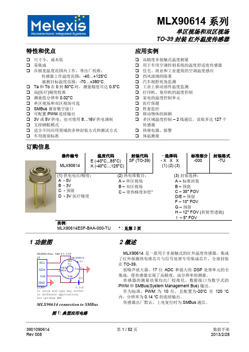
10-位 PWM 输出模式是连续输出所测物体温度的标准配置,测量物体的温度范围为-20…120 °C,分辨 率为 0.14 °C。PWM 通过修改 EEPROM 内 2 个单元的值,实际上可以根据需求调整至任何温度范围,而这对 出厂校准结果并无影响。
传感器的测量结果均出厂校准化,数据接口为数字式的 PWM 和 SMBus(System Management Bus) 输出。
作为标准,PWM 为 10 位,且配置为-20˚C 至 120 ˚C 内,分辨率为 0.14 ˚C 的连续输出。
传感器出厂默认,上电复位时为 SMBus 通信。
3901090614 Rev 008
PWM 引脚也可配置为热继电器(输入是 To),这样可以实现简单且性价比高的恒温控制器或温度报警(冰 点/沸点)应用,其中的温度临界值是用户可编程的。在 SMBus 系统里,这个功能可以作为处理器的中断信号, 以此触发读取主线上从动器的值,并确定精度条件。
传感器有两种供电电压选择:5V 或 3V(电池供电)。其中,5V 也可简便的从更高供电电压(例如 8 至 16V)上通过外接元件调制。(具体请参考“应用信息”)
MLX90614 connection to SMBus
图 1: 典型应用电路
2 概述
MLX90614 是一款用于非接触式的红外温度传感器,集成 了红外探测热电堆芯片与信号处理专用集成芯片,全部封装 在 TO-39。
低噪声放大器、17 位 ADC 和强大的 DSP 处理单元的全 集成,使传感器实现了高精度,高分辨率的测量。
KIRAY 100红外测温仪说明书

Infrared thermometer KIRA Y 100 with dual laser sighting is a key tool to diagnose, inspect and check any temperature, with the advantage of using “no-contact” technology. You can safely measure surface temperatures of hot objects, dangerous or difficult to access. Perfect tool to take temperature in a house, a garage, a workshop, an office, a car, a kitchen etc...Spectral response ..................8 - 14 µmOptical .....................................D.S : 20:1 (13 mm at 260 mm)Temperature range .................From -50 to +800°CAccuracy*...............................From -50 à +20°C : ±2.5°CFrom +20 to +300°C : ±2% of reading ±2°C From +300°C to +800°C : ±2% of readingInfrared repeatability ..............From -50 to +20°C : ±1.3°CFrom +20 to +800°C : ±0.5% or ±0.5°CDisplay resolution ..................0.1°C Response time .......................150 msEmissivity ...............................Adjustable from 0.10 to 1.0 (pre-set at 0.95)Over range indication ............Display indication : « ---- »Dual laser sighting .................Wave length : from 630 nm to 670 nmOutput < 1mW, Class 2 (II)Positive or negativetemperature indication ................Automatic (no indication for a positivetemperature)(-) sign for a negative temperatureDisplay ....................................4 digits with LCD backlighted display Auto-extinction .......................Automatic after 7 seconds of inactivity High/low alarm .......................Flashing signal on display and beep signalwith adjustable thresholdsPower supply ..........................Alkaline 9V batteryAutonomy ...............................105 h (inactive laser and backlight)20 h (active laser and backlight)Use temperature .....................From 0 to +10°C for a short periodFrom +11 to +50 °C for a long periodStorage temperature ..............From -10°C to +60°CRelative humidity ...................From 10 to 90%HR in operating modeand > 80%RH in storageDimensions .............................145 x 95 x 40 mmWeight .....................................180 g (included battery)Make sure that the target is larger than the size of the laser sighting.Technical featuresDistance from the targetKIRAY 100Infrared thermometerDistance Diameter 254260508mm 12.71325.4mmD:S=20:113 mm at 260 mmYES NO*Accuracy for an ambient temperature from 23 to 25°C (with a relative humidity lower than 80% RH)Kimo KIRAY 100 Infrared Thermometer1 – Up button. It allows to increment emissivity and high/low alarm thresholds.This button also allows in measurement mode to activate or deactivate the laser.2 – Mode button. It allows to navigate through the modes (emissivity, lock, high alarm, low alarm).3 – Down button. It allows to decrement emissivity and high/low alarm thresholds.This button also allows in measurement mode to activate or deactivate thebacklight.123Battery compartmentTriggerDescriptionSet technical unit (°C/°F)LCDbacklighted display Up buttonMode buttonDown buttonIR sensor(infrared)KIRAY 100 buttons1 – Technical unit °C/°F2 – Low battery indicator3 – Emissivity value = 0.95 (factory setting)4 – Max temperature indicator.5 – Temperature value6 – Current measurement indicator7 – HOLD indicator (fixed measurement)8 – Laser in operation indicator9 – Lock indicator (continuous measurement)10 – High alarm symbol (fixed : activated alarm ; flashing + beep : alarm thresholds exceeded)11 – Low alarm symbol (fixed : activated alarm ; flashing + beep : alarm thresholds exceeded)Display●Case with passer-by belt ●User manualCE CertificationThis device meets with following standards' requirements.EN 50081-1 : 1992, Electromagnetic compatibility, Part 1EN 50082-1 : 1992, Electromagnetic compatibility, Part 2Infrared thermometer, how does it work ?Infrared thermometers canmeasure the surfacetemperature of an object. Its optic lens catches the energy emitted and reflected by the object. This energy is collected and focused onto a detector. This information is displayed as temperature. The laser pointer is only used to aim at the target.Laser sighting Infrared sensorEmitted energy by theobject as radiationSupplied withOutput laser sighting。
- 1、下载文档前请自行甄别文档内容的完整性,平台不提供额外的编辑、内容补充、找答案等附加服务。
- 2、"仅部分预览"的文档,不可在线预览部分如存在完整性等问题,可反馈申请退款(可完整预览的文档不适用该条件!)。
- 3、如文档侵犯您的权益,请联系客服反馈,我们会尽快为您处理(人工客服工作时间:9:00-18:30)。
产品特色
完全支持 Quick Charge 2.0 规范
A 类:5 V、9 V 及 12 V 输出电压 B 类:5 V、9 V、12 V 及 20 V 输出电压 可选的 12 V 和/或 20 V 输出抑制 兼容 USB 电池充电规范 1.2
自动 USB DCP 短路 D+至 D-线路 默认 5 V 模式工作 支持 TOPSwitch 和 TinySwitch 待机功耗极低
为满足自适应快速充电系统的需求,Power Integrations 开发出了“ChiPhy”(充电接口物理)系列 IC。与 Power Integrations 的 AC-DC 开关 IC(如 TOPSwitch 或 TinySwitch)结合使用,ChiPhy IC 能够将自适 应快速充电功能增加到 AC-DC 墙插式充电器。 Power Integrations 的 ChiPhy IC 产品系列中的第一款器件是 CHY100,它专为 Quick Charge 2.0 平台而 设计。如果设备不兼容 Quick Charge 2.0 协议,ChiPhy IC 可禁止输出电压调整,以确保充电安全。ຫໍສະໝຸດ PI-6988-071713
Figure 1.
Typical Application Schematic.
Description
CHY100 is a low-cost USB high-voltage dedicated charging port (HVDCP) interface IC for the Quick Charge 2.0 specification. It incorporates all necessary functions to add Quick Charge 2.0 capability to Power Integrations’ switcher ICs such as TOPSwitch or TinySwitch and other solutions employing traditional feedback schemes.
BP V3 V2 D+
Feedback Network
CHY100 U1
DR
V1 GND
Typical Applications • Battery chargers for smart phones, tablets, netbooks, digital cameras, and bluetooth accessories • USB power output ports
+
V2
CLR
V1
N2
+
0.325 V 19.58 kΩ 2V
N1
N4
GROUND (GND)
PI-7009-071513
Figure 3.
Functional Block Diagram.
Pin Functional Description
GROUND (GND) Pin Ground. V1 Pin Open Drain input of output voltage adjustment switch. Active for 9 V, 12 V, and 20 V output setting. V2 Pin Open Drain input of output voltage adjustment switch. Active for 12 V, and 20 V output setting. V3 Pin Open Drain input of output voltage adjustment switch. Active for 20 V output setting. BYPASS (BP) Pin Connection point for an external bypass capacitor for the internally generated supply voltage. REFERENCE (R) Pin Connected to internal band-gap reference. Provides reference current through connected resistor. DATA LINE D+ Pin USB D+ data line input. DATA LINE D - Pin USB D- data line input.
5 V 输出电压时低于 1 mW 故障时安全运行
相邻引脚间短路故障 开路引脚故障
典型应用
智能手机、平板电脑、上网本、数码相机和蓝牙附件的电池充电器 USB 功率输出端口
性能曲线
上图所示 CHY100 在三种不同的输出电压下测量出來的输出特性曲线
输出电压
D+ (V)
0.6 3.3 3.3 0.6
捷多邦,您值得信赖的PCB打样专家!
CHY100
快速充电 2.0 的充电器实体接口 IC
图 1. 典型应用电路图
说明
自适应快速充电是一种最新的 USB 电池充电技术, 其充电速度比传统充电器快 75%。 高通的 Quick Charge 2.0 协议处于这项技术的最前列。Quick Charge 2.0 的工作原理是:在检测到来自支持 Quick Charge 2.0 的设备(如手机和平板电脑)所发出的指令后,调整 AC-DC 充电器的输出电压,使设备的电池获得更大 的功率输入。
July 2013
CHY100
BYPASS (BP)
+
BANDGAP
+
REFERENCE (R)
6V
3.9 V
2V GND
+
0.325 V OUTPUT INHIBIT D+
V3
CONTROL LOGIC N3 (LOOKUP TABLE)
S R
SET
Q N5 DQ
Figure 2. Package Option.
SO-8 (D Package)
CHY100 supports the full output voltage range of either Class A or Class B. Optionally Class B can be inhibited for protecting the battery charger from accidental damage. CHY100 automatically detects whether a connected Powered Device (PD) is Quick Charge 2.0 capable before enabling output voltage adjustment. If a PD not compliant to Quick Charge 2.0 is detected the CHY100 disables output voltage adjustment to ensure safe operation with legacy 5 V only USB PDs.
•
VOUT D+ DGND
•
• • •
Fully supports Quick Charge 2.0 specification • Class A: 5 V, 9 V, and 12 V output voltage • Class B: 5 V, 9 V, 12 V, and 20 V output voltage USB battery charging specification revision 1.2 compatible • Automatic USB DCP shorting D+ to D- line • Default 5 V mode operation Supports TOPSwitch and TinySwitch Very low power consumption • Below 1 mW at 5 V output Fail safe operation • Adjacent pin-to-pin short-circuit fault • Open circuit pin fault
VOUT D1 C1 R6 R1 RDAT_LKG RBP U3
BP
Reference Input Resister RREF at the REFERENCE pin is connected to an internal band gap reference and provides an accurate reference current for internal timing circuits. The recommended value is RREF = 127 kΩ. Quick Charge 2.0 Interface At power-up CHY100 turns on switch N5 (see Figure 3) in 20 ms or less after the BYPASS pin voltage has reached 4 V. Switch N4 and output switches N1 to N3 remain off. This sets the default 5 V output voltage level. With D+ and D- short-circuited the normal handshake between the AC-DC adapter (DCP) and powered devices (PD) as described in the USB Battery Charging Specification 1.2 can commence. After switch N5 has been turned on CHY100 starts monitoring the voltage level at D+. If it continuously stays above 0.325 V for at least 1.25 seconds CHY100 will enter Quick Charge 2.0 operation mode. If the voltage at D+ drops any time below 0.325 V CHY100 resets the 1.25 seconds timer and stays in USB Battery Charging Specification 1.2 compatibility mode with a default output voltage of 5 V. Once CHY100 has entered Quick Charge 2.0 operation mode switch N5 will be turned off. Additionally switch N4 is turned on connecting a 19.53 k Ω pull-down resistor to D-. As soon as the voltage at D- has dropped low (<0.325 V) for at least 1 ms CHY100 starts accepting requests for different AC-DC adapter output voltages by means of applied voltage levels at data lines D+ and D- through the powered device. Table 1 summarizes the output voltage lookup table, corresponding AC-DC adapter output voltages and status of switches N1 to N3. D+ 0.6 V 3.3 V 3.3 V 0.6 V