A Workbench for Prototyping XML Data Exchange (extended abstract)
Trados简体中文简明教程
Trados 中文简明教程1. 准备工作 . . . . . . . . . . . . . . . . . . . . . . . . . . . . . . . . . . . . . . . . . . . . . . . . . 3 1.1 准备MultiTerm . . . . . . . . . . . . . . . . . . . . . . . . . . . . . . . . . . . . . . . . . . . . . . . . . . . . . . . .3 1.2 准备Translator's Workbench . . . . . . . . . . . . . . . . . . . . . . . . . . . . . . . . . . . . . . . . . . . .3 1.2.1 输入用户名 . . . . . . . . . . . . . . . . . . . . . . . . . . . . . . . . . . . . . . . . . . . . . . . . . . . . . . . . . . .4 1.2.2 创建一个翻译记忆库 . . . . . . . . . . . . . . . . . . . . . . . . . . . . . . . . . . . . . . . . . . . . . . . . . . . .41.3 Word的准备工作(在交互翻译环境下) . . . . . . . . . . . . . . . . . . . . . . . . . . . . . . . . . . . .42. 在Word环境下翻译 . . . . . . . . . . . . . . . . . . . . . . . . . . . . . . . . . . . . . . . . 5 2.1 复制术语 . . . . . . . . . . . . . . . . . . . . . . . . . . . . . . . . . . . . . . . . . . . . . . . . . . . . . . . . . . . . .6 2.2 确认一句译文并转向下一句 . . . . . . . . . . . . . . . . . . . . . . . . . . . . . . . . . . . . . . . . . . . . . . .6 2.3 用“Translate to Fuzzy”自动翻译100%匹配部分 . . . . . . . . . . . . . . . . . . . . . . . . . . .7 2.4 使用相关搜索 . . . . . . . . . . . . . . . . . . . . . . . . . . . . . . . . . . . . . . . . . . . . . . . . . . . . . . . . . .7 2.5 复制原文 . . . . . . . . . . . . . . . . . . . . . . . . . . . . . . . . . . . . . . . . . . . . . . . . . . . . . . . . . . . . .7 2.6 清理已翻译的文档 . . . . . . . . . . . . . . . . . . . . . . . . . . . . . . . . . . . . . . . . . . . . . . . . . . . . . .8Workbench的其它功能和特性 . . . . . . . . . . . . . . . . . . . . . 8 3. Translator's3.1 选择译文的颜色 . . . . . . . . . . . . . . . . . . . . . . . . . . . . . . . . . . . . . . . . . . . . . . . . . . . . . . . .8 3.2 为不同项目定义属性字段和文本字段 . . . . . . . . . . . . . . . . . . . . . . . . . . . . . . . . . . . . . . . .9 3.2.1 定义属性 . . . . . . . . . . . . . . . . . . . . . . . . . . . . . . . . . . . . . . . . . . . . . . . . . . . . . . . . . . . . .9 3.2.2 定义文本字段 . . . . . . . . . . . . . . . . . . . . . . . . . . . . . . . . . . . . . . . . . . . . . . . . . . . . . . . . . .93.3 自动替换 . . . . . . . . . . . . . . . . . . . . . . . . . . . . . . . . . . . . . . . . . . . . . . . . . . . . . . . . . . . . .94. 处理更新文件 . . . . . . . . . . . . . . . . . . . . . . . . . . . . . . . . . . . . . . . . . . . . 10 4.1 启用 Project Settings(项目设置) . . . . . . . . . . . . . . . . . . . . . . . . . . . . . . . . . . . . . . .10 4.1.1 在翻译过程中加入属性字段和文本字段 . . . . . . . . . . . . . . . . . . . . . . . . . . . . . . . . . . . . .10 4.2 分析不同版本的项目 . . . . . . . . . . . . . . . . . . . . . . . . . . . . . . . . . . . . . . . . . . . . . . . . . . .11 4.3 翻译更新后的文档 . . . . . . . . . . . . . . . . . . . . . . . . . . . . . . . . . . . . . . . . . . . . . . . . . . . . .11 4.3.1 自动翻译 . . . . . . . . . . . . . . . . . . . . . . . . . . . . . . . . . . . . . . . . . . . . . . . . . . . . . . . . . . . .11 4.3.2 替换数字、缩写、日期、时间、度量单位和固有名词 . . . . . . . . . . . . . . . . . . . . . . . . . .124.4 校对并修改译文 . . . . . . . . . . . . . . . . . . . . . . . . . . . . . . . . . . . . . . . . . . . . . . . . . . . . . . .135. 清除在Word中修改后的文件原文. . . . . . . . . . . . . . . . . . . . . . . . . . . . 135.1 通过相关查询检查记忆库的内容 . . . . . . . . . . . . . . . . . . . . . . . . . . . . . . . . . . . . . . . . . . 136. 为其他用户翻译相似的项目 . . . . . . . . . . . . . . . . . . . . . . . . . . . . . . . . . .13 6.1.1 根据项目设置启用过滤器 . . . . . . . . . . . . . . . . . . . . . . . . . . . . . . . . . . . . . . . . . . . . . . . 14 6.1.2 通过“罚分”机制降低其它项目翻译单元的匹配值 . . . . . . . . . . . . . . . . . . . . . . . . . . . 146.1.3 启用过滤器和“罚分”机制进行交互翻译. . . . . . . . . . . . . . . . . . . . . . . . . . . . . . . . . . 147. 翻译仅须少量更新文件的捷径 . . . . . . . . . . . . . . . . . . . . . . . . . . . . . . . .15Translation Memory高级选项 . . . . . . . . . . . . . . . . . . . . . . . . . . . . . . . . . . . . . . . . . . 16术语识别选项(Term Recognition Options) . . . . . . . . . . . . . . . . . . . . . . . . . . . . . . 16相关查询选项(Concordance) . . . . . . . . . . . . . . . . . . . . . . . . . . . . . . . . . . . . . . . . . 17 8. 疑难解答 . . . . . . . . . . . . . . . . . . . . . . . . . . . . . . . . . . . . . . . . . . . . . . . .17 8.1 翻译过程 . . . . . . . . . . . . . . . . . . . . . . . . . . . . . . . . . . . . . . . . . . . . . . . . . . . . . . . . . . . . 178.2 清除原文过程 . . . . . . . . . . . . . . . . . . . . . . . . . . . . . . . . . . . . . . . . . . . . . . . . . . . . . . . . 189. TagEditor使用简介 . . . . . . . . . . . . . . . . . . . . . . . . . . . . . . . . . . . . . . .18 9.1 翻译HTML文件 . . . . . . . . . . . . . . . . . . . . . . . . . . . . . . . . . . . . . . . . . . . . . . . . . . . . . . 18 9.2 翻译SGML文件 . . . . . . . . . . . . . . . . . . . . . . . . . . . . . . . . . . . . . . . . . . . . . . . . . . . . . . 199.3 翻译S-Tagger文件 . . . . . . . . . . . . . . . . . . . . . . . . . . . . . . . . . . . . . . . . . . . . . . . . . . . 2010. 项目文件 . . . . . . . . . . . . . . . . . . . . . . . . . . . . . . . . . . . . . . . . . . . . . . . .2011. TW按钮和高端字符快捷键 . . . . . . . . . . . . . . . . . . . . . . . . . . . . . . . . . .20 11.1 用键盘快捷键替代TW按钮 . . . . . . . . . . . . . . . . . . . . . . . . . . . . . . . . . . . . . . . . . . . . . 2111.2 高端字符输入 . . . . . . . . . . . . . . . . . . . . . . . . . . . . . . . . . . . . . . . . . . . . . . . . . . . . . . . . 2112. 主要TW按钮和快捷键 . . . . . . . . . . . . . . . . . . . . . . . . . . . . . . . . . . . . .21 2Trados 中文简明教程1. 准备工作在本次培训的开始阶段,您将首先了解“翻译记忆”(Translation Memory)的概念。
ansys workbench材料库(Engineering Data)
B
工具条Toolbar
Engineering Data和分析方案的快捷操作
C
工具箱Toolbox
包括了用来定义材料属性的各项目,如密度,杨氏模量等
D
Engineering DataSources窗口
创建,编辑,检索材料,并保存你经常使用的材料
E
信息展开窗口Outline Pane
材料库——
1.
1.1
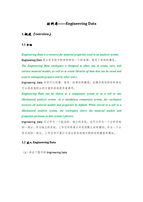
Engineering Data is a resource for material properties used in an analysis system.
Engineering Data是分析系统中的材料特性一个的来源,规定了材料的属性。
The Engineering Data workspace is designed to allow you to create, save, and retrieve material models, as well as to create libraries of data that can be saved and used in subsequent projects and by other users.
3.1.1
Engineering Data will filter the data which pertains to the project system being edited, by default. The filtering is based on the Physics, Analysis Type, andSolver. You can turn filtering on and off in the toolbar ( ). All data is transferred to the solver regardless of filtering being turned on or off.
Digimat总体介绍

9
Digimat-MF: Microstructure
Inclusion Phase(s)
Inclusion Shape (Ellipsoids of Revolution): Constant/Distribution
• Platelets (AR< 1) • Spheres (AR=1) • Fibers – Short – Long – Continuous
Outputs – At the macro & micro scales (i.e. composite & phase)
Stiffness & Compliance Matrices Coefficient of Thermal Expansion (CTE) Thermal Conductivity Electric Conductivity Stress-Strain Curves Strengths Distribution of stresses & strains in each phase of the composite
Automotive Aerospace Electronics & Consumer Products Wind Energy Defense Industrial Products Medical Devices Other: Academic, R&D Institutes, …
Thursday, November 24, 2011
Copyright© e-Xstream engineering, 2011
•2
Material Engineering with Mean Field & Finite Element based homogenization
workbench中文

workbench中⽂⼀、Definition1.Stiffness behavior (刚度特性)Flexible (灵活的)rigid(刚性)Gasket (垫⽚)2.suppressed(抑制)3.Coordinate system(坐标系统)Default Coordinate system (缺省坐标系统)4.Reference Temperature(参考温度)⼆、Material1.Assignment(分配)2.Nonlinear Effects(⾮线性效应)3.Thermal Strain Effects (热应变影响)三、Properties(性质)1.centroid(质⼼)2.Moment of Inertia IP1 (转动惯量)四、Statistic(统计)1.Mesh Metric(⽹络指标)⼀、Definition1.Element Control(元素掌控)Program Controlled(受控程序)Manual(⼈⼯,⼿动)2.Display Style (显⽰样式)Body ColorPart ColorMaterialNonlinear Material Effects Stiffness Behavior⼆、Properties (性质)1.scale Factor value(⽐例因⼦的值)三、Basic Geometry Options (基本⼏何选项)1.Parameters (参量)2.Parameter key(主要参数)3..Attributes(特性)/doc/2451a0457********edb11e9.html d Selections (按名称选择)5.Material Properties(材料属性)四、Advanced Geometry Options (⾼级⼏何选项)/doc/2451a0457********edb11e9.html e Associativity(使⽤结合性)2.Reader Mode Saves Updates File(读者模式保存更新⽂件)/doc/2451a0457********edb11e9.html e Instances(使⽤实体实例)4.Smart CAD Update(智能CAD更新)5.Attach File Via Temp File(附加⽂件通过临时⽂件)6.Temporary Directory(暂时⽬录)7.Analysis Type(分析类型)8.Decompose Disjoint Faces9.Enclosure and Symmetry Processing (外壳和对称处理)⼀、Definition1.TypeCartesian(笛卡尔)Cylindrical (圆柱形)2.Coordinate System(坐标系)Program Controlled(受控程序)Manual(⼿动,⼈⼯)Coordinate System ID(坐标系统ID)⼀、Scope1.Scoping MethodGeometry Selection(⼏何选择)Named Selection(名称选择)⼆、Definition1.Type2.Scope Mode3.Behavior4.Suppressed三、Advanced1.Formulation(调配)Program ControlledAugmented Lagrange(⼴义拉格朗⽇法)Pure Penalty(罚函数法)MPC(微程式控制)Normal Lagrange(拉格朗⽇法)2.Detection MethodProgram ControlledOn Gauss Point(在⾼斯点)Nodal-Normal From Contact (从接触)Nodal-Normal to Target(⽬标节点正常)Nodal-Projected Normal From Contact (从接触结点预计正常)3.Normal Stiffness(法向刚度)4.Update Stiffness(更新刚度)Never Each Iteration(每次迭代)Each Iteration,Aggressive5.Pinball Region(弹球区域)Auto Detection ValueRadius(半径)。
A-Foundation-for...

A-Foundation-for...are under pressure to get their products onto store shelvesahead of the competition. To address increased productcomplexities while also meeting shortened design cycletimes, a proven approach is to add simulation softwareto the R&D process. Introducing analysis tools enables a design engineer to generate a model as a virtual representation of a physical geometry and then use physics-based calculations to refine and optimize a product. This can be much faster than the historical method of trial-and-error prototyping. Consequently, leading organizations have adopted simulation processes for many engineering disciplines. Traditionally, engineers use flu-ids, thermal, structural or electronic analysis tools separately to design a specific aspect of a product. By considering the different physics in isolation, however, engineers are unable to account for all the effects designs may impose on other disciplines or other functionality of the overall system-level design.ANSYS capabilities allow engineers to gain in-depth under-standing of particular cross-physics phenomena and how they relate to one another. An engineer concerned with electrical power delivery can simulate how much loss he or she is see-ing within a circuit board by accounting for changes in mate-rial resistivity due to joule heating of the conductors. Through ANSYS Workbench, industry-leading structural, thermal, fluids and electromagnetic field solvers are brought together to enable true multiphysics simulations. Geometry can be shared automat-ically between these solvers, since design changes made for one solver may also have an impact on the predictions from another solver being used to model the same or an adjacent section of a design. Using the shared geometry, a Workbench project can be set up so that different physics domain experts can each con-figure the proper single-physics simulation for their particularANALYSIS TOOLSA FOUNDATION FOR COLLABORA TION Multiphysics simulation in ANSYS Workbench powers system-level analysis and helps shorten design cycles.By Guy Barnes, Lead Technical Services Engineer; Zoran Dragojlovic, Technical Services Engineer;and Jared Harvest , Senior Technical Services Engineer, ANSYSI n the fast-paced consumer electronics market, companiesdiscipline, thus providing a systems-level analysis of multiple physics within the same user interface. This approach to col-laborative design means all disciplines can be addressed in the initial stages of simulation — not during costly prototyp-ing or end-production stages.A real-life example of a design chal-lenge involving multiphysics is an elec-trical power delivery device, which must meet specific standards to be put on store shelves. U.S. Federal Communications Commission (FCC) regulations on elec-trical emissions as well as standards for acoustic noise in a public office envi-ronment and thermal considerations for product reliability must be satisfied. Electrical emission testing can be simu-lated in ANSYS HFSS, which is a 3-D finite element electromagnetic field solver, to determine if the design will pass FCC electromagnetic interference (EMI) spec-ifications. In this case, HFSS can help a designer see that changing the venting configuration from larger slots and open -ings to smaller round holes would block unwanted emissions.Though the smaller holes are help-ful in controlling electrical emissions, they may pose a problem for the ther-mal management engineer if the vents restrict the air flow necessary for cool -ing, which could result in overheating. Thermal analysis using ANSYS Icepak can eliminate the need to build and test several design variations. Icepak is an electronics thermal management simulation tool for modeling systems such as integrated circuit (IC) packages and printed circuit boards (PCBs). This software accounts for all of the heat transfer effects with robust computa -tional fluid dynamics (CFD) technol -ogy, enabling the engineer to predict the internal temperature on the device while it is powered on with the cooling fan running.Changing the vent configurationmay require increasing the fan speedGeometry of example electrical power supply device. These devices must meet severalspecific standards for electrical emissions, heat output and noise level before they can bemade available for sale to the public.HFSS simulation predictions show electromagnetic fields radiating from the initial thermalventing configuration. The proposed design fails to meet FCC specifications in a 3-meter emissions test because the peak values are too high.To address product complexities while meetingshortened design cycles, a proven approach is to add simulation software to the R&D process.Using HFSS in conjunction with Icepak,EMI and thermal engineers can work together to find a solution to their joint design goals.to prevent overheating. For example, the original vent con-figuration operating at a power consumption of 6 Watts keeps the internal temperatures under the target of 110 degrees C while running a fan at 3,500 RPM. With smaller vent openings, the fan speed must be increased to 4,600 RPM to stay below the same target temperature. Using HFSS in conjunction with Icepak, thermal and EMI engineers can work together to find a solution to their joint design goals. If increasing the fan speed is not an option, the EMI engi-neer could try different venting shapes or even incorporate an optimization approach to address both thermal and EMI criteria.Once the electromagnetic effects and heat transfer have been taken into account, the aero-acoustics must be consid-ered. Modifying the vent design and increasing fan speed addressed EMI and thermal needs, but these changes may affect the acoustic noise that the device emits during its operation. Consumers will not accept a noisy fan running in their home or workspace, so devices that use fans as part of thermal management have to operate at low noise levels. ANSYS Fluent can answer questions about noise levels via aero-acoustic CFD analysis. The sound-pressure level (SPL) amplitudes over the range of frequencies audible to humans are derived from pressure fluctuations at a receiving point located in the fan inlet region that is just outside of the cas-ing. The original design was predicted to generate less than 50 decibels (dB) of noise at audible frequencies, which is low enough to blend into background noise in an average home. With the modified vent configuration and resulting higher fan speed, the peak sound pressure level of 56 dB occurs at the frequency of 311 Hz. This is comparable to conversa-tional speech at a distance of 1 meter.During device operation, the turbulent fluctuations of pressure interact with the solid surfaces of the fan, casing and electronic components, turning them into sources of acoustic noise. A special Fluent utility can be used to gen-erate 3-D contour plots of noise sources inside the device for a given range of frequencies. This can aid the design process by identifying the regions with high values of SPL. For example, the core turbulent region generated by the fan interacts with the fan blades and the large electronic com-ponents placed near the fan. This interaction results in ele-vated noise levels in the region between the fan and the two components. Addressing this issue requires further design changes.Through this example of an electrical power supply, simulation with the multiphysics capabilities available in ANSYS Workbench allows engineers to evaluate numerousphysical aspects of virtual design variations without theThe second HFSS simulation shows the effects of ventilation changeson electromagnetic emissions. The red line is the electromagnetic emissions at 3 meters for the initial design, and the blue line shows predictions for the modified design.Two design changes made in response to initial HFSS predictions:(top) replacing large fan ventilation opening; (bottom) replacing sideventilations slots with greater number of small round holesInternal temperatures and air flow path predicted by Icepak insideoriginal design. The original vent configuration operating at a power consumption of 6 Watts keeps the internal temperatures under the target of 110 degrees C while running a fan at 3,500 RPM.ANALYSIS TOOLSlaborious process of having to build and test every one of them. By using a simu-lation-driven process, engineering teams are enabled to work together more cohe-sively and accelerate development of new technology. When time to market is so critical, companies cannot afford design failures that appear late in the process. With a suite of industry-leading solvers working together under the same hood, ANSYS Workbench offers the ability to analyze multiple physics from the overall system level, allowing critical issues to be identified early in the design stages and enhancing the product development process.Reported results of Icepak simulation onupdated design with smaller venting holes. To maintain the target of less than 110 degrees C, the fan speed must be increased to 4,600 RPM.With the modified vent configuration and resulting higher fan speed, the peak sound pressure level of 56 dB (blue line) occursat a frequency of 311 Hz. This is comparable to conversational human speech at a distance of 1 meter.Fluent results showing spatial distribution of acoustic noise sources driven by near-wall turbulent fluctuations of local air pressure, including vortexcore regions colored by eddy viscosity (left) and sound pressure level at 500 Hz (right)ANSYSWorkbenchenables analysis of multiple interactingphysics, allowing critical issues to be identified early in the design stages.HIGH-PERFORMANCEELECTRONIC DESIGN: PREDICTING ELECTROMAGNETIC INTERFERENCE/doc/abace0f6b4daa58da1114a6d.htmlHIGH-PERFORMANCE ELECTRONIC DESIGN: PREDICTING ELECTRO- MAGNETIC INTERFERENCE/doc/abace0f6b4daa58da1114a6d.html /82foundation OPTIMIZATION IN ELECTRONICS THERMAL MANAGEMENT USING ANSYS ICEPAK AND ANSYS DESIGNXPLORER/doc/abace0f6b4daa58da1114a6d.html /82foundation2。
workbench应力奇异点 子模型法

workbench应力奇异点子模型法摘要:1.引言2.workbench 简介3.应力奇异点的概念4.子模型法的原理5.子模型法在workbench 中的应用6.结论正文:1.引言在工程领域中,有限元分析是一种重要的数值模拟方法,用于解决复杂的三维应力、应变和温度分布问题。
然而,在某些情况下,传统的有限元方法可能无法有效地捕捉结构中的应力奇异点。
为了解决这一问题,本文将介绍一种基于子模型法的workbench 应力奇异点分析方法。
2.workbench 简介workbench 是一款强大的有限元分析软件,用户可以通过其友好的界面轻松地建立、分析和可视化有限元模型。
workbench 提供了丰富的分析功能,包括线性和非线性结构分析、热传导分析、热膨胀分析等。
3.应力奇异点的概念应力奇异点是指在结构中应力分布出现极值或不连续的点。
在实际工程中,应力奇异点通常与结构的薄弱环节、疲劳破坏和失效模式等现象密切相关。
因此,准确地识别和分析应力奇异点对于评估结构的安全性和可靠性具有重要意义。
4.子模型法的原理子模型法是一种基于有限元分析的应力奇异点识别方法。
其主要思想是将结构划分为多个子区域,然后在每个子区域内进行应力分析。
通过比较不同子区域之间的应力响应,可以确定应力奇异点的位置和分布。
子模型法的优点在于它能够有效地降低计算复杂度,提高分析效率。
5.子模型法在workbench 中的应用在workbench 中,用户可以利用子模型法进行应力奇异点分析。
具体操作步骤如下:a) 建立有限元模型:首先,用户需要创建一个包含结构的几何模型,并为其定义材料属性。
b) 划分子模型:接下来,用户需要将结构划分为多个子区域,以便在每个子区域内进行应力分析。
c) 设定边界条件:为了进行有限元分析,用户需要为模型定义边界条件,包括固定约束、转动约束和加载条件等。
d) 运行分析:在完成模型设置后,用户可以启动分析作业,workbench 将自动计算每个子区域内的应力分布。
Utility for Caching Metafile Renditions For Matrix

Utility for Caching Metafile Renditions For MatrixTable of Contents Introduction (3)How does it work? (3)What is a metafile? (3)Supported Document Formats for Metafile Renditions (3)Steps for Creating Metafiles (4)i.For Files with XREFs (3D Assemblies or 2D files with XREFs) (4)ii.For all other files (4)Architecture (5)Administrator Guide (6)System Requirements (6)Installation (6)Manual Setup (7)Starting the Utility (9)Configuration (10)Setting Trigger Mechanisms in Matrix (10)i.On-Demand Mechanism (10)ii.Event-Based Mechanism (11)Enabling Icon Mail for Matrix Users (15)Feedback (16)General Inquiries (16)Sales Inquiries (16)Customer Support (16)IntroductionMetafile Utility uses the AutoVue server as a rendition tool to generate and check metafiles into the Matrix Product Data Management system (Matrix PDM). Once a metafile rendition is added to the native document, the next time the file is viewed in the AutoVue client, the AutoVue server fetches the metafile rendition instead of the native file.How does it work?Here is a brief description of how the utility handles requests for creating metafile renditions:1. The client application sends the rendition request to the PDM server.The actual request dispatched by the client depends on the triggering mechanism, which can be configured on the PDM server side. Examples of triggering mechanisms include check-in, promotion, or on-demand actions.2. The Server stores the request in a special queue item.Each queue item represents a request made by a client to generate a metafile rendition of the native file.3. The utility polls the queue items from the PDM at predefined intervals, and retrieves any pending requests.4. The utility sends relevant information of each request to the AutoVue server to generate the metafile rendition.5. The utility asks AutoVue server to check-in the metafile rendition to the PDM.The AutoVue server in turn passes the request to VueLink to add the metafile as a rendition to the nativedocument object in the PDM.What is a metafile?A metafile is a true replica of the original file. It is a lightweight format developed by Cimmetry. Its main advantage is performance enhancement of document viewing on the client side.Supported Document Formats for Metafile RenditionsThe utility generates metafile renditions for all Engineering and Vector formats that are supported by AutoVue Client-Server Edition. Currently, AutoVue Client-Server Edition supports many file formats, including 2D engineering drawings and 3D assemblies.Steps for Creating MetafilesFor Files with XREFs (3D Assemblies or 2D files with XREFs)Special care is given when creating a metafile for files with XREFs. For the utility to properly generate a metafile for a particular file, follow these steps:1. Launch the Matrix client application and login.2. Check in all the XREFs and the assembly, then define the relationship between the master file and the XREFs.3. If the On-Demand trigger mechanism is setup, select the Assembly business object, right-click and selectExecute > csiCreateQueueItemOnDemand from the popup menu.4. If the Event-Based trigger mechanism is setup, check out the Assembly and check it back into Matrix.For All Other FilesIf the Event-Based trigger mechanism is setup, the metafile request is generated as soon as the file is checked into Matrix.ArchitectureWhenever a predefined event occurs, such as a file check-in for example, Matrix invokes a server-side custom program called csiCreateQueueItem, which creates a custom object inside a Matrix vault. This custom object represents a unique Rendition Request.Meanwhile, a polling application retrieves these queue items from Matrix, using API provided by VueLink, extracts information from the QueueItem to identify the checked-in document. This information is added to an internal Queue, which is polled by a QueueReader. Each entry retrieved by the QueueReader is then dispatched to the AutoVue Client-Server Edition server using Vuebean API. Thereafter, the metafile is created and checked into Matrix by the AutoVue Client-Server Edition server, which interacts with VueLink for Matrix for this purpose. The status of the rendition, whether it is “Errored” or “Successful” is then sent back to the user by the Polling Application using Matrix Icon Mail.The Polling Application and the QueueReader run asynchronously, leading to greater efficiency.Administrator GuideSystem RequirementsThe utility itself is a Java application program and therefore can be run on any platform equipped with Java Virtual Machine (JVM).The following software must already be installed on the machine hosting this utility:•Sun's Java Runtime Environment (JRE) 1.4.2 or higher•Matrix Thick Client Applications v10.7- At least the MQL Application.The following software must also be available for the utility to work but may be installed on a different machine than the one hosting the utility:•AutoVue Client-Server Edition v19.1 (or any SP of v19.1)•Matrix Collaboration Kernel 10.7•VueLink for Matrix v19.1•Matrix Application Exchange Framework AEF 10.7•Matrix Engineering Central or Designer Central 10.7InstallationMetafile utility requires the AutoVue Server and VueLink. Before installing Metafile Utility with Matrix, make sure that Matrix, AutoVue Client-Server Edition, and VueLink for Matrix are properly installed and configured on your system, according to the manufacturer’s instructions, and are operating correctly.To install the utility for caching metafiles for Matrix, complete the steps outlined in the following sections:•Manual Setup•Setting Trigger Mechanism in Matrix•Enabling Icon Mail for Matrix Users•Starting the UtilityManual SetupTake the following steps to install Metafile Caching Utility manually. If you installed Metafile Caching Utility during the automatic installation of VueLink, skip the following steps.1. Create a folder called /cimmetry/metafile_utility. For example: c:/program files/cimmetry/metafile_utility2. Copy the content of the ‘metafile_utility’ folder found on the distribution CD to the folder created in previousstep.3. In the /metafile_utility/bin folder, open ‘run.bat’ in a text editor and modify the following settings:JDK_DIR Full path to the root folder where Sun’s JRE is installed. Example: c:\jdk1.3.1JARDIR Full path to the folder that contains metafile.jar along with other JAR files.PASSWORD Password of a valid Matrix account with administrative privileges.MX_CLIENT_JAR There are two entries in run.bat. You need to uncomment one entry only based onversion of Matrix you have installed. If you are using Matrix v9.5.2.0+,eMatrixServletRMI.jar should be in the classpath. Otherwise,eMatrixAppletDownloadXML.jar should be in the classpath.If you are using RIP mode, use full path to eMatrixAppletXML.jar instead ofeMatrixServletRMI.jar.Note:By default, the csiqcmatrix.properties file is located under same folder as metafile.jar. If this file is moved to another location, then you need to set the full path to PROPFILE.PROPFILE Full path to csiqcmatrix.properties file.4. In the /metafile_utility/bin folder, open the ‘csiqcmatrix.properties’ file in a text editor and modify thefollowing settings:JVUE_HOST The host server Name or IP where AutoVue Client-Server Edition Server isrunning.JVUE_PORT The Port Number to which AutoVue Client-Server Edition Server is listening. Bydefault, this value is 5099.MAX_THREADS For each request for rendition, the utility creates a new thread (process) thatinteracts with the AutoVue Server to perform the rendition as well as the check-in ofthe metafile. The maximum number of such threads that the polling client can runsimultaneously can be configured here. Increasing this number leads to quickerrendition because more files can be rendered at the same time. But it also leads toa greater load on the machine hosting this utility as well as the machine hostingAutoVue Server. This number cannot exceed the number of seats procured forAutoVue Client-Server Edition Server. For example, if you are running AutoVueClient-Server Edition server with a 50-user license, then the value supplied in thistext field may never exceed 50.QUEUE_CLIENT_PROP Full Path to csimfmatrix.properties properties file.5. In the /metafile_utility/bin folder, open ‘csimfmatrix.properties’ file in a text editor and modify the followingsettings:MX_HOST The host server Name or IP where the Application Server (e.g. Weblogic) hostingMatrix Thin Client applications is running.MX_PORT Any Matrix Thin Client installation needs a Webserver to be the point of entry for allrequests. The Webserver then transfers requests to the underlying application server.For example, when the Weblogic server is installed, it comes with a default Webserverthat listens to port 7001 by default and transfers all requests to Weblogic.The value supplied in this text field should be the port number to which the Webserver islistening.MX_CONNECT Matrix Collaboration Kernel type. RIP,RMI or EJB. Default is RIP.If using RIP mode, input MX_CONNECT is APPSERVER.MX_RMIPORT Port number if Matrix RMI server is used. Default is 1099.MX_USER Name of valid Matrix user with Administrative Privileges to Application Centrals.Default is Test Everything. The utility needs to sign into Matrix to access RenditionRequests. This user ID should have permissions to read and modify Business Objectsof type csiQueueItem. It should also have permissions to send icon mail notifications tousers about the status of their rendition requests.MX_VAULT Matrix vault name, which contains all the csiQueueItems. Care should be taken toensure that this is the same Vault that contains VueLink for Matrix specific businessobjects.MX_CSI_CONFIG This object (Cimmetry Configuration Business Object) is created whenVueLink for Matrix is installed. It contains all the required meta-data for VueLinkfunctionality. Since this utility depends on VueLink to function (please refer to thearchitecture diagram), the object name specified here should be accurate. CODEBASE Web path to the client file specified above (MX_CLIENT_JAR), with web app contextname. Example: /ematrix/WebClient/java/classesMX_FILEURL Web path to MxAutoVue servlet. Example: /ematrix/servlet/MxAutoVueServletMX_SVLT Web path to VueLink servlet. Example: /ematrix/com.cimmetry.vuelink.matrix.DMS6. In a text editor, open ‘schemaCreateBC.txt’ file found under /metafile_utility/bin folder and modify thefollowing settings:context_user Replace "__USER__" with the name of valid Matrix user who has administrativeprivileges. Default is creator.context_password Replace "__ PASSWORD __" with the password of valid Matrix user who hasadministrative privileges. Default is empty.context_vault Replace "__VAULT__” with Matrix Vault name.store_name Replace "__STORE__" with Matrix Store name.7. Launch Matrix MQL Application (mql.exe) and run the script contained in ‘schemaCreateBC.txt’ file. Forexample, at MQL prompt, type run c:/temp/schemaCreateBC.txt.Starting the UtilityInvoke ‘run.bat’ from the command line. It asks you for a password. Enter a password that belongs to a valid Matrix user who has administrative privileges.Make sure that Application Server (Weblogic or WebSphere) is running before invoking ‘run.bat’.ConfigurationSetting Trigger Mechanisms in MatrixMetafile Utility for Matrix takes advantage of the event mechanism provided by Matrix. Two kinds of triggering mechanisms are employed with Metafile Utility:The On-Demand (explicit) mechanism, metafile request is implemented with Matrix Thick-client. The user can initiate a metafile request when needed. The metafile Utility takes care of that request and creates the metafile.Note:• The On-Demand mechanism is recommended for files with XREFs.The Event-based (implicit) mechanism, the triggering method is involved with registering with a particular event such as the check-in event. That means once a document is checked in, an event, which is defined by Matrix is fired which invokes ‘csiCreateQueueItem’ program.Note:• The Event-Based mechanism is recommended for files without XREFs.On-Demand MechanismThe script file creates a program called ‘csiCreateQueueItemOnDemand’ within Matrix. This program functions exactly like the program “csiCreateQueueItem”. The difference is that “csiCreateQueueItem” is meant to be associated with Business Objects as a trigger while this program is to be associated with Business Objects as a method. The administrator may also associate the program “csiCreateQueueItem” with Business Object types other than CAD Model.1. Run Matrix Business application (eg.: business.exe).2. Open the Matrix CAD Model type in edit mode.3. In the Edit window that appears, click the Methods tab.4. Click Add.5. Type “csiCreateQueueItemOnDemand” in the Name field.6. Click Ok.Event-Based Mechanismii-1 csiCreateQueueItemThe script file creates a program called csiCreateQueueItem in Matrix. When invoked, this program creates a Business Object, which represents a request for Metafile Rendition. You can set the ‘Check-in’ trigger on CAD Model Business Objects to invoke this program. You can choose to associate the program with any other trigger.In addition to this, you can also associate the csiCreateQueueItem program with Business Object types other than CAD Model.1. Run Matrix Business application (eg.: business.exe).2. Open the Matrix CAD Model type in edit mode.3. In the Edit window that appears, click the Triggers tab.4. If the trigger you want is not in the list, click Add, then double-click the desired trigger.5. In the Edit Trigger window that appears, type the program name, i.e. csiCreateQueueItem, in the Action textfield.ii-2 csiCreateQueueItemMeetingThe script file creates a program called “csiCreateQueueItemMeeting” in Matrix. When invoked, this program creates a Business Object, which represents a request for Metafile Rendition. You can set the Create trigger on MeetingAttachment Relationship Business Objects to invoke this program. You can choose to associate the program with any other trigger.In addition to this, you can also associate the “csiCreateQueueItemMeeting” program with Business Object types other than MeetingAttachment.6. Run Matrix Business application (eg.: business.exe).7. Open the Matrix MeetingAttachment type in edit mode.8. In the Edit window that appears, click the Triggers tab.9. If the trigger you want is not in the list, click Add, then double-click the desired trigger.10. In the Edit Trigger window that appears, type the program name, i.e. csiCreateQueueItemMeeting, in the Actiontext field.11- Make sure the Meeting Attachments relationship is from Type Meeting to Type DOCUMENTS as well. In this case, the trigger would act on any type of document that is derived from type DOCUMENTS successfully.Enabling Icon Mail for Matrix UsersOnce the utility is installed successfully, you need to enable icon Mail for all users who will be creating Rendition Requests. This is needed because the utility relies on icon mail to send notification to users about the status of their requests.1. Run the Matrix Business application (eg.: business.exe).2. Select Object > Find from main menu.3. Select Person from the Object list, then click Find.4. From the search result, select the user who needs icon mail enabling.5. Select Object > Open > Edit from main menu.6. In the Edit window that appears, make sure the Icon Mail box is checked.FeedbackCimmetry System products are designed according to your needs. We would appreciate your feedback, comments and suggestions. We can be contacted by fax, e-mail or telephone. There is a feedback button on our Web page that activates an easy-to-use feedback form. Let us know what you think!General InquiriesTelephone: +1 514-735-3219Fax: (514) 735-6440E-mail: *****************Website: Sales InquiriesTelephone: +1 514-735-3219 or 1-800-361-1904Fax: (514) 735-6440E-mail: ******************Customer SupportTelephone: +1 514-735-9941Website: http://support。
workbench中的几个常见问题(转)

workbench中的几个常见问题(转)1.This solver engine was unable to coverage on a solution for the nonlinear problem as constrained.2.Detected initial penetration/ gap is relatively large for certain contact pairs. This may produce inaccurate results for bonded and no separation contacts using formulation other than MPC. This large penetration/ gap can be indentified by generating the initial contact results.3. At least one body has been found to have only 1 element in at least 2 directions along with reduced integration. This situation can lead to invalid results. consider changing to full integration element control or meshing with more elements.4. The uncoveraged solution(identified as substep 999999) is output for analysis debug purposes. Results at this time should not be used for any other purpose.5. one or more contact regions may not be in initial contact. check results carefully6. contact status has experienced an abrupt change. check results carefully for possible contact seperation7. one or more bodies may be underconstrained and experiencing rigid body motion. weak springs have been added to attain a solution.8. copying the source mesh to the target face failed because of the poor quality. please review your surface mesh, review the mesh, and set or adjust size controls to help the sweeper generate higher quality source and target surface meshes. after you are satisfied please generate the volume mesh again.1,说你计算是由非线性问题导致不收敛2,说你接触对有大的间隙问题,不晓得你用什么接触,但下面这四个地方值得你借鉴:3,说你网格有问题,仔细划分一下网格吧,接触面上的网格大小要尽量一致,用size控制一下边啊,面啊、体啊啥的,最好用六面体网格(可用multizone 方法)。
- 1、下载文档前请自行甄别文档内容的完整性,平台不提供额外的编辑、内容补充、找答案等附加服务。
- 2、"仅部分预览"的文档,不可在线预览部分如存在完整性等问题,可反馈申请退款(可完整预览的文档不适用该条件!)。
- 3、如文档侵犯您的权益,请联系客服反馈,我们会尽快为您处理(人工客服工作时间:9:00-18:30)。
A Workbench for Prototyping XML Data Exchange(extended abstract)Renzo Orsini and Augusto CelentanoUniversità Ca’ Foscari di Venezia, Dipartimento di Informaticavia Torino 155, 30172 Mestre (VE), Italy{orsini,auce}@dsi.unive.it1 IntroductionThis paper describes a prototype software which is the outcome of a research carried at the Ca’ Foscari University of Venice in the framework of the project Data-X1. The software is a workbench for “data engineers”, integrating several tools which assist the user in all the tasks of integration and exchange of data with a standard format, for instance for application integration, generation of content-rich web portals, building of virtual information systems, etc. The system described here is a first step towards the construction of a “data hub”: with this term, we intend a comprehensive tool which, like a network hub device, connects several information sources and consum-ers through standard ports, allowing the designer to dynamically interconnect these ports in different ways, and performing appropriate translations. Such a tool would be of great help for the tasks above mentioned, and its existence is made possible by the nowadays wide acceptance of XML.Data exchange on the WWW has received a lot of attention due to the rapid diffu-sion of the proposal of XML as standard for information description by the W3 Con-sortium. The complete flexibility and generality of the XML markup mechanism as well as its platform-independence, allows its use in many contexts as a language for describing data of any kind, not only for documents to be published on WWW. What is missing is either a tool or a linguistic level to denote the meaning and type of data, since the XML markup mechanism only denotes the logic structure of data. Currently, XML allows neither description of the semantics nor that of the internal representa-tion of data, with respect to applications. The DTD (Document Type Declaration) is of little help to address semantics issues, because it only describes the structural scheme of the document parts composition. The internal representation of data cannot be used since XML is text-based and platform independent, therefore data should be translated in a standard alphanumeric coding by other means.When exchanging data between different data sources, or between data sources and applications by using an XML based mechanism, this omission may limit the possibil-ity of verifying data coherency. This involves both the formalization aspects (type) and the semantics aspects (meaning). This problem is a big roadblock in many appli-cation areas.1The details of the project Data-X: Management, Transformation and Exchange of Data in a Web Envi-ronment can be read at the URL http://www.difa.unibas.it/dataX/2 Aforrapid prototypingworkbenchWe propose a development environment for a data engineer, which helps her/him to 1. map relational database schemas into XML DTD’s, and vice versa, trying to matchas closest as possible different schemas, possibly with missing elements;2. transfer data between the two sides, a relational DB at one side and an XMLdocument at the other side, in both directions, preserving as much as possible the data structure according to the designer’s will;3. generate programs and DTD for executing and validating data exchange;4. combine and integrate such programs for building complex systems and Web-based data-oriented applications.The system should have a visual interface for defining the mapping between the different data producers and consumers, in order to keep it simple even for users not skilled in the programming techniques normally needed for performing format and data conversion. A visual environment can avoid the need for learning the languages used for performing queries and data restructuring.Figure 1 shows the overall architecture of the current workbench prototype. As a workbench, it is a collection of tools which, while being coordinated, retain their individual functionality and style of use. An effort has been done to minimize the differences in the interaction with each tool, by building a common interface. The workbench generalizes and integrates some functions of the different tools, such as window management, file management, database connections. However the tools have different goals and come from different experiences, and also tools developed out of the project are candidates for integration. Moreover, since the workbench is oriented towards data exchange, the tools are mainly focused on XML data-centric documents.The functions of such a workbench should allow a user, through a visual interac-tion style, to:Figure 1. The architecture of the workbench prototype1. match relational schemas and XML DTDs against libraries of schemas and tem-plates (via the DTDMatch tool);2. generate XML data from complex queries on relational databases (via theDBtoXML tool);3. store data of XML documents into relational databases (via the XMLtoDB tool);4. query information about database schema and metadata (via the InfoDB tool);5. generate Java code to perform the data exchange at application level (via theDBtoXML tool);6. transform XML documents using languages like XSLT or graphical tools for map-ping structures and contents.Not all the functions are currently integrated into the workbench, some of them are external programs, a few are still under development. Nevertheless the workbench provides a useful environment for prototyping data exchange applications both be-tween data sources and destinations, and between data sources and applications. The prototype is tuned to the InterBase 6 DBMS [1], but its JDBC interface allows fast porting on other system.3 DTD analysis and schema matchingThe DTDMatch tool approaches the problem of matching a set of XML DTDs against a view schema drawn from a relational database. Its goal is to evaluate their similarity as a preliminary step of relational tables translation into XML documents. It auto-matically computes the correspondence between a relational schema and a set of DTDs taken from a library based on a set of similarity parameters, returning a ranked list of DTDs from which the user can select the most appropriate one. This approach is intended as a support to design data integration with predefined (e.g., standard) document schemas. We expect that, unless relational views and DTDs come from a coordinated design, we can obtain only partial matches between the two structures. Some data belonging to the DB view will not be considered by the XML document schema, and the XML schema could require (or accept as an option) data which are not part of the relational DB view.As the other tools of the workbench, DTDMatch is oriented to prototyping and re-use; a system for evaluating the degree of correspondence between database data and document schemas can help to develop prototypes at low cost with great flexibility. Details of the matching operations and of the underlying data model are in [6].DTDMatch is based on the tree-structured model of XML documents and DTDs described in [3]. An XML document is modeled as a loto (labeled ordered tree ob-ject). Nodes correspond to XML elements and their labels provide the type names of the elements. A loto type definition (ltd) models DTDs in a similar way.The problem of matching a relational view schema to a set of DTDs is translated into the problem of building ltd s from relational views and from DTDs, and compar-ing them by computing a similarity measure. The similarity is defined not only by a numeric value denoting the degree of structural correspondence, but also by the list of the corresponding nodes in the two ltd s.We must consider that two ltd s are similar to the degree that they represent equiva-lent information, both from the structural and conceptual viewpoints. From the struc-tural viewpoint, the correspondence between nodes and subtrees of the ltd s comparedFigure 2. A panel showing results of DTD matching.must cover as much as possible of the two structures. From the conceptual viewpoint, types and labels in the nodes must correspond (at some extent). A thesaurus defines weighted synonymy among names, while type compatibility is defined a priori.Figure 2 shows one of the panels of the tool, showing the results of a match. DTDMatch allows a user to:• define and execute SQL queries and build the ltd which represents the schema of the result;• build a library of XML DTDs, imported or converted from SQL query results, and edit them;• build and maintain a thesaurus storing synonymous names;• edit the coefficients which bias the similarity computation;• compute similarity between the ltd corresponding to the SQL query in input and the ltd s selected from a library;• select one DTD and build an XML document with the data returned by the SQL query.The experiments we have done show that the ranking proposed by the matching algorithm is plausible as long as DTDs do not differ seriously from the query schema. The structural similarity between the ltd s is based on the reciprocal position of nodes and leaves in the ancestors and sibling nodes. In this way the tool models the need that a rich structure, organized along different aggregation levels, should be preserved in XML translation, and conversely a simple structure should not artificially grow.4 DB to XML translation and data exchangeThe DBtoXML tool has been built on top of Visual SQL-X [5, 7], a visual system which assist the user in querying a relational database to produce XML documents of arbitrary complexity. Differently from the DTDMatch tool it is not based on the automatic selection or generation of the document schema. Rather, it is a fully interac-tive tool that allows a user to specify step-by-step the structure of the query and of the corresponding XML document. The queries are expressed in SQL-X[4], an extension of SQL which, with a style reminiscent of report generation languages, allows the extraction of trees of data from a relational database as XML documents.The tool hides the language syntax to the user, by providing a graphical interface which allows the construction of a query as a tree, which reflects the structure of the expected result.An example of query is shown in Figure 3. The query tree models the ltd of the expected resultand its nodes can be of one the following kinds: <Root> is the tree root, and represents the whole document, containing a set of elements corresponding either to tuples or to groups of tuples extracted from the database. <Rel> represent a database relation (obtained in general through an SQL query), whose set of tuples are converted into elements of its immediate container. <Att> (child of <Rel>), represents a column, a value of which is used as element of its container. <Nest> represents the tuples of a relation which are associated, with a join operation, to a tuple of its con-tainer, and which will become roots of subtrees. <Group> represents the grouping of the tuples of a child node by some expression: each group is an element containing the tuples of the group as elements.For each node, the user is given the possibility of specifying all the parameters of the corresponding operation. Besides these kinds of nodes, the user can specify if tuple fields are converted to attributes, instead of elements, the ordering of sequences, as well as other details of the conversion process.The main panel of the tool is the query editor (Figure 3), which allows the con-struction of the query tree by selecting a node and then applying an operator. In this case, the tree represents a query which returns a set of clients. They are grouped byFigure 3. The query editor in DBtoXML.country, and each client contains an element with its name, and another one with the sequence of the product code and date of its orders. When a node is selected, the right panel shows the associated information, which depends on the node: for <Root>, the ordering of its elements; for <Rel>, the fields which are the elements’ attributes; for <Nest>, the join condition, the ordering of its elements, and possibly other conditions on the tuples corresponding to the subelements; for <Group>, the grouping condition (e.g. the field ‘Country’ of ‘Clients’), an ordering for its subelements, and the group’s element attributes. For instance, the definition of the node corresponding to the set of orders for each client is shown in Figure 4a.The system facilitates the task of the user by providing a set of panels for compos-ing conditions and other expressions (e.g. with aggregation functions) during the construction of the tree. In the prototype, the user can follow, with a set of panels, all the phases of the evaluation of the query: the conversion in SQL and the resulting relation, the tree which is the result of the data extraction, and the final document. For instance, the query of the example is translated into the following SQL query: SELECT ,Orders.ProductCode,Orders.DateFROM Clients,OrdersWHERE(Clients.Code=Orders.ClientCode)while in Figure 4b the loto of the resulting XML document is shown (only a few ele-ments are expanded).In any phase of the evaluation, the user can go back and change its definition, for instance to experiment different grouping and nesting strategies. For the lack of space, the final documents, together with its DTD, is not shown here.The approach taken in translating the query into SQL is that of collecting all the necessary data into a single relation, which is then read only once for producing the resulting XML document. The example previously shown is in effect a very simple query: all the work is made in the final phase, which, through a visit of the query definition tree, generates an intermediate tree containing all the data (the loto tree), which can be directly mapped to the DOM representation of the document.5 XML to DB translationThe XMLtoDB tool has been developed to produce, with a graphical interface, a map-ping from XML data-centric documents to relational databases. The basic ideas which rule the mapping are very simple:• a text-only element (leaf) can map to a column;• a non-leaf element can map to a relation;• if an element B is nested inside an element A (its immediate ancestor), then B can be mapped to a column of the table mapped to A, if B is a leaf, or it can be mapped to rows of the database which are associated to the rows of A through some external key.The mapping is established by visiting in preorder the DTD of the document which contains the data. We assume that the DTD is not recursive since we are dealing with data-centric documents, which are strictly hierarchical. For each node one of the fol-lowing three possibilities is established:1. ignore the node and all of its descendents: no mapping is performed and the corre-sponding document subtree is ignored;2. “pass through”: ignore the node, but continue the mapping over its descendents;3. map the node to a database element, with a set of constraints. The constraints which govern the mapping process ensure that the data transferredin the database are correct with respect to the relational model, and are the following:1. different DTD elements cannot be mapped to the same DB element;2. non leaf nodes must be associated only to tables in the DB;3. leaf nodes must be associated only to columns;4. if a node N whose only descendents are leaf is associated to a table T, then the descendents of N can be associated only to columns of T.Figure 5 shows the main panel of the tool. The black lines show some illegal map-pings, the labels refer to the list above. The user selects the DTD nodes in the order in the upper left panel, and applies one of the operators ignore , pass through or map . For the latter, a corresponding DB element is selected. The current associations are listed in the lower panel. At the end of this phase, the global consistency of the operation is checked, in particular all the NOT NULL columns of a mapped table must have re-ceived some value. The values of external keys in a row are automatically taken from the primary key of the row inserted for the corresponding father element. The system then produces a file which can be processed by an ad hoc modification of the XMLDBMS package of Bourret [2].6 Other toolsThere are other tools currently integrated in the workbench:1. the InfoDB tool, which extracts both metadata and excerpts of data from a database and presents them in a graphical panel for the user to browse;2. facilities to save and restore partial results, like Visual SQL-X queries in the DB to XML tool, and map files in the XML to DB tool;3. a tool to compile Visual SQL-X queries and DB mappings in Java programs, which can be saved to be used thereafter. The generation is based on a set of predefined(a) (b) Figure 4. (a) Editing a node in DBtoXML , (b) The resulting XML document.templates that can be adapted by the user to particular tasks.The workbench prototype integrates with a unique, coherent interface several inde-pendent tools for the exchange of data in XML format. Until now the DBtoXML and XMLtoDB tools are completely integrated, while the DTDMatch tool is still external. New tools are being developed to extend the functionalities of the system, like a DTD to DTD mapper, which translates XML documents in other documents with different DTDs, as well as new facilities for working with complex projects.7 AcknowledgmentsThe work has been supported by MURST, the Italian Ministry of University and Re-search in the framework of the project Data-X: Management, Transformation and Exchange of Data in a Web Environment. The workbench has been developed with the co-operation of Massimo Pagotto, Matteo De Franceschi and Marica Bamberghi.8 References[1] Borland, Interbase, /interbase/.[2] R. Bourret, “XML and Databases”, /XMLAndDatabases.htm.[3] B. Ludaescher, Y. Papakonstantinou, P. Velikhov, V. Vianu, “View Definition and DTDInference for XML”, /~ludaesch/Paper/icdt-ws99.html.[4] R. Orsini, “A preliminary proposal for SQL-X: A Language to Extract XML Documentsfrom Relational Databases”, SEBD 2000, L’Aquila, June 2000.[5] R. Orsini, M. Pagotto, “Visual SQL-X: A graphical tool for producing XML documentsfrom Relational Databases,” WWW10, Poster Proceedings of the 10th International World Wide Web Conference, Hong-Kong, 2001.[6] M. Pagotto, A . Celentano, “Matching XML DTD To Relational Database Views”, SEBD2000, L’Aquila, Jun 2000.[7] M. Pagotto, R. Orsini, “Visual SQL-X: Uno strumento grafico per l’estrazione di docu-menti XML da basi di dati relazionali”, SEBD 2001, Venezia, June 2001.。