压力释放阀说明书[中英]
压力释放阀说明书中英

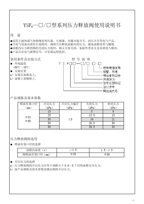
压力释放阀适用于油浸式电力变压器、电力电容器及有载分接开关等,用来保护油箱。
当油浸式变压器在运行中出现故障时,由于线圈过热,使一部分变压器油汽化,变压器油箱中压力迅速增加,这时压力释放阀在2ms内迅速动作,释放压力,保护油箱不致变形或爆裂。油箱内的压力再升高而达到开启压力时,压力释放阀应再次动作,直到油箱内的压力降到正常值。由于压力释放阀动作后能可靠关闭,油箱外的水和空气不能进入油箱,变压器内部不会受大气污染。
The Operation Instruction is applicable to pressure release valve of a series of transformers manufactured by our company, indicating its application, performances, specifications, technical parameters, usage and installation for uses’ reference.
阀(valve)
释放(release)
压力(pressure)
注:特殊环境代号note: special environment:
TA: 干热带地区dry tropic
TH: 湿热带地区 humid tropic
T: 干、湿热带地区dry、humid tropic
例:YSF16-55/130KKJT开启压力为55kPa,喷油口径为φ130mm,带电信号、机械信号。适用于干、湿热带地区的压力释放阀。
1.Application andperformance
Pressure release valves play avital role in the protection of oil-immersed electrical equipments, such as transformers, high voltage switch gears, capacitor and on load tap-changers, etc. This device can prevent the oil-immersed electrical equipment from deformation or rupture. Should a fault occur in such electrical equipment, from deformation of rupture?Should a fault occurring in such electrical equipment, they are instantaneously vaporize the oil causing extremelyrapid build-up of gaseous pressure?If mounting this type pressure release device on the oil-tank, when the pressure reaches to its opening pressure, it opens automatically within 2ms and relieves the pressure.
Marsh Hawk TRV 1系列4000压力释放阀说明书

v e n t i n g| g a u g e h atc h e sS E R I E S4000 M A R S H H AW K T RVFeatures• Premium deep-set gauge hatch with integral pressure & vacuum relief offers superior performance in normal and cold conditions.• reliable, bubble-tight sealing with standard Fkm ( viton) seal and stainless steel spring.• Field adjustable pressure settings, from 2 ozsi to 32 ozsi.• manual relief, inconel trim, alternative seals and various coatings optionally available.F E AT U RE SDeep-set venting gauge hatch• the series 4000 marsh hawk trv offers tank access combined with pressure and vacuum reliefin a deep-set design.• situating valve seats below the tank roof permits latent heat from the product to keep the seals ice-free.Reliable, bubble-tight sealing• the series 4000 has class-leading sealperformance as compared to any other premium or economy venting gauge hatch currently available.• improved sealing performance eliminates flutter and periodic small-scale venting which can cause frost closure in competitor top-mount hatches.Variety of pressure settings• the series 4000 marsh hawk pressure relief is adjustable between 2 ozsi and 16 ozsi in 2 ozsi increments.• the optional double-weight spring allows relief pressure between 18 and 32 ozsi, in 2 ozsiincrements.• 1 ozsi increments optionally available.• vacuum relief is fixed at 0.4 ozsi.Suitable for Sour Service• the series 4000 is ready for sour service out of the box with Fkm ( viton) seals and stainlesssprings.• For more adverse applications, alternative seal and spring materials are available, along withhard anodization or fusion-bond epoxy coatings.S P E C I F I C AT I O NS¹temperatures provided are continuous service temperatures for the indicated seal materials. see the short term extended service temperatures below in “seal materials and configuration” section.D I M E N S I O NSFalse-colour cutaway of a series 4000 marsh hawk trv showing the deep-set seal (orange), pressure spacers(blue) and springs (red).F LOW C H A R AC T E R I S T I C-3.2-3-2.8-2.6-2.4-2.2-2-1.8-1.6-1.4-1.2-1-0.8-0.6-0.4-0.20T A N K V A C U U M , V (O Z S I )024681012141618202224262830323436384042444648505254565860626401234567891011121314151617181920212223242526272829303132333435T A N K P R E S S U R E , P (O Z S I )FL OW RA T E T H R O UG H M A R S H H AW K, Q , X 1000 SCF H (AIR)O P T I O N S A N D AC C E S S O R I E SManual Reliefthe manual relief option allows an operator to manu-ally activate the vent.Pressing the hatch cover’s large red button on the actu-ates the vacuum pallet, relieving pressure in the tank to allow safe removal of the spider cage assembly for tank gauging or hatch maintenance. the button and actuating poppet are supported independently of the vacuum disc, and do not interfere with normal relieving operation.Hard Anodized (Type III)For situations requiring improved corrosion resistance over the standard marsh hawk, a hard anodization option is available. this electrochemical process in-creases the thickness and durability of the ceramic-like natural aluminum oxide layer.all aluminum components are anodized to meet miL-a-862F type iii engineering hardcoat. the anodization slightly darkens the cast components and imparts a slight bronze tinge to the machined components.anodization improved performance in moderate brines, as well as acetic, boric and nitric acid. For prolonged exposure to concentrated brines, or strong mineral acids, consider the severe service coating.Severe Service CoatingFor situations demanding the highest corrosion resis-tance, consider the severe service coating.the body of the marsh hawk is coated with a red Fusion Bond epoxy (FBe) for resistance to mineral acids,(including sulphuric and hydrochloric acids up to 15%) high-chloride ion solutions (including alumi-num chloride, potassium chloride and brine) as well as many other petrochemicals.the marsh hawk internals are coated in a proprietary black PFa (teFLOn) providing the same excellent fluo-ropolymer chemical resistance as the FBe above.series 4000 marsh hawk trv with manual relief Optionseries 4000 marsh hawk trv with hard anodizationseries 4000 marsh hawk trv with severe service coatingO P T I O N S A N D AC C E S S O R I E S (C O N T I N U E D )S E A L C O N F I G U R AT I O N A N D M AT E R I A L S the series 4000 marsh hawk combines the pressure and vacuum valve in an innovative design that requires only one shared gasket.to improve valve sealing performance, gaskets are factory coated with a pliable silane-based sealant. an optional oil-based sealant for use in sour gas applica-tions is also available. Both sealants are available in small packages for maintenance and reapplication.hawkeye offers three material options for the pressure / vacuum seal, beyond the standard Fkm (viton®) seal.• For applications where sealing is the first priority and the vent is not expected to operate often and has low set pressures (under 4 ozsi), eFkm (sponge viton®) can be supplied.• For higher temperature, minimally freezing conditions and acid service FePm (aflas®) is available.• For extreme applications FFkm (kalrez®) is also available.the use of ePDm seals in any hawkeye vent is contra-indicated due to its unsuitability in common petrochem-ical applications.hawkeye does not offer or recommend using solid fluoropolymer (PtFe, PFa, FeP, etc.), nor expanded flu-ropolymer (gOre-tex®) as a gasket material and any venting device. although the material may be chemi-cally suitable, the harder crystalline polymer structure of these materials impedes sealing at the typically low interfacial pressures found in the marsh hawk, as well as other low-pressure (i.e. <15 psi) vents.GENE R A L FLU OROEL A STOM E R CHEM ICA L C OM PATI BI LI T Y¹FKM / VI TON N.B.¹ THIS CHART I S F OR R EFE REN CE ONLY. ALT HOUG H HAWKEYE STRI VES TO E NSU RE P RE SE NTE D I NF OR MATI ON I S ACCURATE, A QUALIF I ED PE RSON SHO ULD EN SURE TH E SUI TABILI T YO F A S E LECTED MATER IA L I N T HE SPECIF IC CHEMI CAL, TEMP ERATURE A ND PRE SSU RE C O NTE XT O F TH EI R APPLI CATIO N.² SH OWN F OR COMPA RI SON PURPOSE S ON LY, NOT AVA ILABLE AS A SEAL M ATE RIAL O N H AW KE YE VE N TS60330OPE R AT I NG TE M PE R ATU R E , °CNOR MA L RAN G EVITON IDHOLE AFLAS IDHOLES KALREZ ID HOLESID E N T IF Y IN G M AR S H H AWK GAS K E T M AT E R I A LMesh Hata formed 10 mesh 304 stainless steel cover to keep insects and debris from interfering with the marsh hawk internals.De-icing Systemallows direct injection of a seal-appropriate de-icing solution onto the marsh hawk internals from ground level. includes spray nozzle and hose assembly.PA RTS L I S T&M AT E R I A L S O F C O N S T R U C T I ONPAC K AG I N Gseries 4000 marsh hawks are shipped complete and boxed. in addition to the marsh hawk itself,the car-ton contains bolt kit(s), tank gasket(s) and installation instructions.weight is approximately 28 lb [12.7 kg].P R E S S U R E T E S T I N G series 4000 marsh hawks are tested prior to packaging to ensure pressure-tightness and relief setting accuracy. items passing the quality control measures are marked with the label at right.•P A S S•P R E SS UR E T ES T E DV E N T M A R K I N Gthe spider cage assembly of the series 4000 marsh hawk is tagged with the initial factory confi guration of the valve. as the relief pressure is fi eld-adjustable, space is left on the tag to record future set pressures,should they change.C E RT I F I C AT I O Nthe pressure and vacuum relief settings of the series 4000 marsh hawk can be factory certifi ed at an addi-tional expense. certifi ed hatches are accompanied by a certifi cate stating the relief pressure of the hatches.R I S E RS & S P O O L SBolt-on risers account for the slope of the tank roof ensuring the series 4000 marsh hawk sits level for trouble-free operation. adapter spools allow installa-tion of a marsh hawk or other 8” aPi 12B/F device onto an ansi B16.5 fl at-face fl ange or other aPi man-way or tank opening. see the “risers, spools & rings” brochure for more information. 12:1 Bolt-on Hatch Riserthe most popular riser used with the series 4000 marsh hawk, the HRSP-0800, ensures a vertical gauge hatch orientation on a 12:1 sloped tank roof with an existing 8” aPi 12B/F fl at-face connection.[in.][mm.]rh riser height (max) 4.2107rcmin minimum fl ange gap2.563.5P Pitch12:1 4.8°rd Outisde Diameter 12.0305riinside Diameter8.0203the series 4000 marsh hawk is just one part of tank-age product lines from hawkeye industries, that also includes:Vapor Controlseries 5000 ePrv series 6000 Pvrv Mechanical Level Indicationmodel 1000 Redtail & model 1500 Roadside Dry seal Zero emission Level gauging systems model 2000 Goshawk Level transmitter for Dry seal Zero emission Level gauging systemsR E L AT E D P R O D U C TScontents © 2006 - 2021 hawkeye industries inc. this document is uncontrolled, and is subject to change without notice. Please refer to for the most up-to-date product information. 2110 70 ave nwedmonton, aB, canada t6P 1n6toll Free: (800) 910-4295Phone: (780) 490-4295Fax: (780) venting - series 4000 marsh hawk trv 01Jun2021Printed in canada.O R D E R I N G I N F O R M AT I O Nstandard series 4000 marsh hawk configurations are stocked ready to ship. Other configurations are typically assemble-to-order and available in under two weeks. configure your desired series 4000 marsh hawk trv us-ing the part number legend below. items in bold are standard items and have fastest lead times. all series 4000 marsh hawks ship complete with a gr. 5 Bolt kit and cr (neoprene) Base gasket, both upgradable (see below). For project quantities, contact your hawkeye sales rep for delivery schedules.Relief & MaterialOptionsMHMSMesh ScreenMHKD De-icing System0000Accessories Base GasketBolting KitSeries 6000 PVRV。
压力释放阀使用说明书(沈阳金钟)

YSF压力释放阀YSF Pressure release valve使用说明书Instructions沈阳市金钟电器厂Shenyang Jinzhong electrical appliance factoryYSF Pressure release valve带防护罩的YSF4,5型压力释放阀定向喷油螺纹安装的YSF6型压力释放阀With a protective hood Specify the direction of Spray oil , Thread Installed定向喷油法兰安装的YSF7型压力释放阀定向导油法兰安装的YSF8,9型压力释放阀Specify the direction of Spray oil , Flange Installation Specify the direction of Oil Guide,Flange Installation YSF7 Pressure release valve YSF8,9 Pressure release valve- 1 -二, 型号、规格与基本技术参数Models, specifications and basic technical parameters:1, 型号Model :Y S F / D(S)KJTHB压力释放阀Pressure release valve 型号举例Model example: YSF 5 –55 / 130 D(S)KJTHBYSF 代表压力释放阀, 5 代表设计序号, 55 代表开启压力, 130 代表有效口径,YSF On behalf of pressure release valve,5 Serial number of Design,55 Opening pressure,130 Effective aperture D ( S ) 代表开关数量单( 双 ), K 代表电信号, J 代表机械信号, TH 代表湿热带地区,B 代表闭锁装置 D(S) -Switch amount one(two), K -Electric Signal, J - Mechanical signal, TH -Humid Tropics, B-Locking Device 2, 使用条件:-30℃至+100℃ 如遇寒带地区,采用特殊密封圈可满足-45℃Exploitation conditions -30℃ to +100℃ In case the frigid zone area, uses the special seal packing collar to be possible to satisfy -45℃3, 基本技术参数Basic technical parameters :有效口径Effective aperture (mm) 开启压力Opening pressure(KPa)关闭压力(不小于)Close Pressure (Not less than)(KPa)∮25∮5015±58 25 13.5 35 19 55 29.5 ∮80 ∮1303519 55 29.5 70 37.5 85 45.5 13874.5三, 带有电信号的输出接线线路图With electrical signal output wiring circuit diagram:a, 单开关接线线路图 b, 双开关接线线路图 C,双开关接线线路图Single-switch Two-switch Two-switch wiring circuit diagram wiring circuit diagram wiring circuit diagram信号开关接点容量Signal switch contact capacity :AC 220V 5A DC 220V 0.3A(电阻负载Resistive load )- 2 -。
VP500-TF2Z346EN模块型3口驻留压力释放类三口阀门说明书

2 Specifications
2.1 Valve specifications
Fluid
Type of actuation
Internal pilot operating pressure range [MPa] Note 1)
Air N.C. Standard: 0.2 to 0.7
3 Installation - continued
• Products compliant with IP65 enclosures are protected against dust and water, however, these products cannot be used in water.
High pressure: 0.2 to 1.0 MPa
Operating and ambient temperatures [°C] Flow characteristics Response time Duty cycle Max. operating frequency [Hz] Manual override
ranges.
2.3 Indicator light In the DIN terminal type, the light is installed in the connector.
Surge voltage suppressor (for D/Y Z)
Light (for D/Y Z)
Figure 1.
• Contact SMC for altitude limitations.
Caution
• Temperature of ambient environment Use the valve within the range of the ambient temperature specification of each valve. In addition, pay attention when using the valve in environments where the temperature changes drastically.
YSF6型系列压力释放阀说明书
技术支持:024-89378958 89368080
网 址:
E-mail:sales@
service@
4
_____________________________________________________________________________________
沈阳沈变所电气科技有限公司(原沈阳变压器研究所实验厂)
公司地址:沈阳浑南新区世纪路 39 号
邮 编:110179
销售热线:024-89368025 传 真:024-89368108
1
结构及安装尺寸
(a)YSF6Ⅱ型不带开关外形及结构图
(b)YSF6Ⅱ型带开关外形及结构图
(c)YSF6Ⅲ-/25 型压力释放阀外形及结构图
产品外形及安装尺寸
(d)YSF6-/25 型压力释放阀外形及结构图
有效喷油口径 (mm)
Φ25(a,b,c 型) Φ25(d 型) Φ50(a,b 型)
D1 (mm) Φ40 Φ40 Φ67
密封压力 (kPa)
9 15 21 30 33
压力释放阀的选用
● 喷油有效口径的选择 油箱内油重(t)
阀喷油有效口径(mm)
∠1.5 Φ25
1.5~4.5 Φ50
● 开启压力的选择 a)压力释放阀的开启压力应等于或略小于 0.6~0.7 倍的油箱安全压力; b)按产品规格及基本参数表确定阀的开启压力。
重要提示
●闭锁装置应在变压器运行前拆除,确保压力释放阀的正常运行。 ●安装时压力释放阀各零、部件不可随意拆卸。 ●设备运行时,如释放阀开启使标志杆跳起,在查明原因后将标志杆手动复位,解除
报警。
维护与检修
利用电气设备每次停电检修的机会对压力释放阀进行下列检修: ●开启动作是否灵敏,如有卡堵现象应排除。 ●密封胶圈是否已老化、变形或损坏。 ●零部件是否变形或损坏。 ●信号开关动作是否灵活。
压力释放阀说明书[中英]
![压力释放阀说明书[中英]](https://img.taocdn.com/s3/m/2e96aecc76c66137ef06192d.png)
压力释放阀PRESSURE RELEASE VALVE使用说明书OPERATION INSTRUCTION明远电器设备SHENYANG MINGYUAN ELECTRIC EQUIPMENT CO., Ltd.本说明书适用于我公司生产的系列变压器用压力释放阀,阐述其用途、性能、规格、技术参数、使用及安装,供用户参考。
The Operation Instruction is applicable to pressure release valve of a series of transformers manufactured by our company, indicating its application, performances, specifications, technical parameters, usage and installation for uses’ reference.1. 压力释放阀用途和性能压力释放阀适用于油浸式电力变压器、电力电容器及有载分接开关等,用来保护油箱。
当油浸式变压器在运行中出现故障时,由于线圈过热,使一部分变压器油汽化,变压器油箱中压力迅速增加,这时压力释放阀在2ms迅速动作,释放压力,保护油箱不致变形或爆裂。
油箱的压力再升高而达到开启压力时,压力释放阀应再次动作,直到油箱的压力降到正常值。
由于压力释放阀动作后能可靠关闭,油箱外的水和空气不能进入油箱,变压器部不会受大气污染。
1.Application and performancePressure release valves play a vital role in the protection of oil-immersed electrical equipments, such as transformers, high voltage switch gears, capacitor and on load tap-changers, etc. This device can prevent the oil-immersed electrical equipment from deformation or rupture. Should a fault occur in such electrical equipment, from deformation of rupture? Should a fault occurring in such electrical equipment, they are instantaneously vaporize the oil causing extremely rapid build-up of gaseous pressure? If mounting this type pressure release device on the oil-tank, when the pressure reaches to its opening pressure, it opens automatically within 2ms and relieves the pressure.2.型号、规格及基本参数Type, specification and technical parameters2.1 型号的含义 Meaning of typeY S F□—□ / □□□特殊环境代号(Special environment)带机械信号标“J”(“J”:mechanical signal)带信号开关标“K”(“K”:electrical signal)两者都带标“KJ”(“KJ”:Both with signal)喷油有效口径(Caliber of oil-gushing tube)mm开启压力(Opening pressure)kPa设计序号(Design serial number)阀(valve)释放(release)压力(pressure)注:特殊环境代号 note: special environment:TA: 干热带地区 dry tropicTH: 湿热带地区 humid tropicT: 干、湿热带地区 dry、humid tropic例:YSF16-55/130KKJT开启压力为55kPa,喷油口径为φ130mm,带电信号、机械信号。
EATON 比例压力放松阀说明书
ContentsGENERAL DESCRIPTION 3 TYPICAL SECTION 3 FUNCTIONAL SYMBOLS 4 MODEL CODES 5 OPERATING DATA 6 PERFORMANCE DATAPressure override, Off-Load . . . . . . . . . . . . . . . . . . . . . . . . . . . . . . . . . . . . . . . . . . . . . . . . . . . . . . . . . . . . . . . . . . . .8 Pressure override when relieving . . . . . . . . . . . . . . . . . . . . . . . . . . . . . . . . . . . . . . . . . . . . . . . . . . . . . . . . . . . . . . .9 Pressure gain . . . . . . . . . . . . . . . . . . . . . . . . . . . . . . . . . . . . . . . . . . . . . . . . . . . . . . . . . . . . . . . . . . . . . . . . . . . . . . .9 Step response . . . . . . . . . . . . . . . . . . . . . . . . . . . . . . . . . . . . . . . . . . . . . . . . . . . . . . . . . . . . . . . . . . . . . . . . . . . . .9INSTALLATION DIMENSIONSKBCG-6/8 Models . . . . . . . . . . . . . . . . . . . . . . . . . . . . . . . . . . . . . . . . . . . . . . . . . . . . . . . . . . . . . . . . . . . . . . . . . .10 Mounting surfaces . . . . . . . . . . . . . . . . . . . . . . . . . . . . . . . . . . . . . . . . . . . . . . . . . . . . . . . . . . . . . . . . . . . . . . . . . .11 CGVM-6-10-R Subplate . . . . . . . . . . . . . . . . . . . . . . . . . . . . . . . . . . . . . . . . . . . . . . . . . . . . . . . . . . . . . . . . . . . . . .11ELECTRICAL INFORMATIONBlock diagram . . . . . . . . . . . . . . . . . . . . . . . . . . . . . . . . . . . . . . . . . . . . . . . . . . . . . . . . . . . . . . . . . . . . . . . . . . . . .12 Wiring connections . . . . . . . . . . . . . . . . . . . . . . . . . . . . . . . . . . . . . . . . . . . . . . . . . . . . . . . . . . . . . . . . . . . . . . . . .13FURTHER INFORMATION 152EATON Proportional pressure relief valves V-VLPO-MC003-E1 September 20203EATON Proportional pressure relief valves V-VLPO-MC003-E1 September 2020These two-stage pressure relief valves offer extensive application possibilities through their ability to control the pressure setting in proportion to an applied electrical input (up to a pressure limit which is manually adjustable and lockable) .The integral amplifier allows the pressure to be controlled from a low power command signal: either a voltage or current command . The amplifier is mounted in a robust metal housing and electrical connections are via an industry standard 7-pin plug . Factory-set adjustments ensure high reproducibility valve-to-valve .Basic characteristicsMax . pressure . . . . . . . . . . . . . . . . . . . . . . . . . . . . . . . .350 bar (5000 psi) Max . flow rate . . . . . . . . . . . . . . . . . . . . . . . . . . . . . . . .400 L/min (106 USgpm)Mounting face to ISO 6264:For KBCG-6 . . . . . . . . . . . . . . . . . . . . . . . . . . . . . . . . . . . . . AR-06-2-A For KBCG-8 . . . . . . . . . . . . . . . . . . . . . . . . . . . . . . . . . . . . . AS-08-2-AFeatures and benefits • Remote electrical proportional control of pressure from a choice of five pressure ranges per valve size .• Excellent repeatability and stable performance results from cartridge design of mainstage elements .• Low installed cost and space requirement from high power/size ratios (more than double that of many conventional designs) .• On-board ramp adjustment .General descriptionT ypical sectionManual and electricalpilots internallydrained to port T.Model code 7= Blank7-pin plugManual pilot internallydrained to port T;electrical pilot drainedto side drain port u.Model code 7= 37-pin plugu Tapped port on side of pilot head . Manual and electrical pilots drained to side drain port u.Model code 7= 17-pin plug¨¨¨Functional symbolsu Tapped port on side of pilot head .4EATON Proportional pressure relief valves V-VLPO-MC003-E1 September 20205EATON Proportional pressure relief valves V-VLPO-MC003-E1 September 20201KB 8Z 2*9*3G 1034*11A 5*12P*76***13*7*14111Valve typeKB Proportional valve with integral amplifier, B series 2TypeC Pressure relief 3MountingG Subplate mounted 4Interface - ISO 6264With B port high pressure inlet, A port reduced pressure outlet 6 AR-06-2-A 8 AS-08-2-A 5Manual adjustment W Screw/locknut 6Controlled pressure rangeBased on inlet pressure of 350 bar (5000 psi) . Note, with 100 bar (1450 psi) inlet the lower limits will be 2-3 bar (30-43 psi) lower40 100 160 250 3506-40 bar (87-580 psi) 7,75-100 bar (112-1450 psi) 8,5-160 bar (125-2300 psi) 8,5-250 bar (125-3625 psi) 9-350 bar (139-5000 psi)7DrainBlankManual and electrical pilots drain internally to T port 1Manual and electrical pilots drained to side port drain 3Manual pilot internally drained to T port, electrical pilot drained to side port drain 8Manual overridesZ No overrides 9Electrical command options M1+/- 10 volts control signal M24-20 mA control signal 10Ramps3Standard ramp for KBCG- 6/8 valve types 11Command/pressure characteristicA Standard 12Electrical connection PC77 pin connector, without plug supplied PE77 pin connector, with plug supplied PH7As PE7 but with pin ‘C’ used for enable signal PR7as PC7 but with pin ‘C’ used for enable signal 13Coil rating H124V DC amplifier supply 14Design number, 1* series 11Subject to change . Installation dimensions unaltered for design numbers 10 to 19 respectivelyModel codesT o conform to the EC Electromagnetic Compatibility directive (EMC) this KBCG valve must be fitted with a metal 7-pin plug. The screen of the cable must be securely connected to the shell of the metal connector. A suitable IP67 rated connector is available from Eaton, part no. 934939. Alternatively a non IP67 rated connector is available from ITT -Cannon, part no. CA 02 COM-E 14S A7 P .6EATON Proportional pressure relief valves V-VLPO-MC003-E1 September 2020Operating dataStandard test conditions are with antiwear hydraulic oil at 36 cSt (168 SUS) and 50°C (122°F)Maximum pressures:Ports P and X ▲350 bar (5000 psi)Port T ▲ in KBCG-*-****-Z valves2 bar (30 psi)Port T ▲ in KBCG-*-****-1/3-Z valves350 bar (5000 psi)Side drain port ▲2 bar (30 psi)▲ Back pressure at these ports additive to the pressuresetting of the valve.Rated flow at Δp = 6 bar (87 psi):KBCG-6200 L/min (52.8 USgpm)KBCG-8400 L/min (105.7 USgpm)Vent u flow with valve at rated flow1 L/min (0.26 USgpm)u See “Venting”, page 8.Pilot control drain flow, when valve is limiting systempressure, i.e. flow P to T occurring:KBCG-61,3 L/min (0.34 USgpm)KBCG-82,0 L/min (0.53 USgpm)Coil or amplifier rating24V x 40W max. (22 to 36V including 10% pk.-to-pk.max. ripple)Command signal:Volts (see model code 9 - 1)0 to +10V or 0 to -10VInput impedance 47 kΩCommon mode voltage to pin B 4VCurrent (see model code 9 - 2) 4 to 20 mAInput impedance 100ΩValve enable signal:Enable >9.0V (36V max)Disable <2.0VInput impedance 36 kΩ7-pin plug connector Pin DescriptionA Power supply positive (+)B Power supply 0V and current command returnC Valve enable (PH7 & PR7)D Command signal (+V or current in)E Command signal (-V or current GND)F Output monitorView of pins of fixed half G Protective groundElectromagnetic compatibility (EMC)IEC 61326-2-1 (Electrical equipment for measurement, control and laboratory use)Conducted Emissions CISPR11 -2015-06 Ed 6.0/EN55011 - Class A, 150kHz to 30MHzRadiated Emissions CISPR11 -2015-06 Ed 6.0 /EN55011 - Class A, 30MHz – 1GHzRF Continuous Conducted disturbances IEC 61000-4-6, 3Vrms Class A 150 KHz to 80 MHzRF Electromagnetic Field, 80MHz to 1GHZ, 10V/m; 1.4GHz to 2.7GHz, 3V/m; Meets Criterion ASurge: IEC 61000-4-5• DC Power Port : ±1kV• Signal/Control Port : ±1kVElectrical Fast Transients IEC 61000-4-4, Class B• DC Power Port : ±1kV• Signal/Control Port : ±0.5kVElectrostatic discharges (ESD) IEC 61000-4-2, Class B• Air ±8kV• Contact ±4kVROHS Compliance:Complies with: Restriction of Hazardous Substances (RoHS) Directive 2011/65/EUMonitor signal (pin F) 1.7 V/amp solenoid currentOutput impedance10 kΩOperating dataPressure gain See graphFactory setting - Maximum with 100% command signal.Pressure override when relieving and when off-load See graphsLinearity, between 10% and 100% of rated pressure:KBCG-6 models at 100 L/min (26 USgpm)<6%KBCG-8 models at 200 L/min (52 USgpm)<6%Hysteresis<6% (with factory-set dither)Repeatability<1.3% of rated pressureReproducibility, valve-to-valve (at factory settings):Pressure at 100% command signal≤5%Protection:Electrical Reverse polarity protectedEnvironmental IEC 529, Class IP67Mass (weight):KBCG-65,36 kg (11.8 lb)KBCG-86,26 kg (13.8 lb)Supporting products:Auxiliary electronic modules (DIN-rail mounting):EHA-CON-201-A-2* Signal converter See catalog 2410BEHD-DSG-201-A-1* Command signal generator See catalog 2470EHA-RMP-201-A-2* Ramp generator See catalog 2410BEHA-PID-201-A-2* PID controller See catalog 2427EHA-PSU-201-A-10 Power supply See catalog 2410BSubplates, size 03See catalog 2425Mounting bolts n See catalog 2314An Note: If not using Vickers™ recommended bolt kits, boltsmust be to ISO 898 grade 12.9 or stronger.Mounting attitude No restriction, provided that the valve is kept full of fluid through port T.7EATON Proportional pressure relief valves V-VLPO-MC003-E1 September 20208EATON Proportional pressure relief valves V-VLPO-MC003-E1 September 2020Pressure override, off-load Graphs show the minimum pressures obtainable:a) With 0 mA current to the solenoid coil b) When the valve is vented (see following explanation) .Venting When the vent port X (or alternative vent port in the valve body) is connected to the reservoir via a suitable 2-way pilot valve, the mainstage of the relief valve opens to allow full flow from P to T at low pressure drop . The minimum pressure drop is obtained when the pilot valve is also de-energized . The total pressure drop through the venting 2-way valve and pipework is additive to the pressure at P . While the valve is vented the system pressure cannot be controlled via the proportional solenoid . This control feature is frequently used during off-load periods in machine cycle times . If lower off-load system pressures are required then additional full flow unloading valves are recommended, e .g . Vickers™ CV series cartridge valves . Note: All valves are with pilot valve de-energized .Data is typical with oil at 36 cSt (168 SUS) and at 50°C (122°F)024810bar 60255075100125psiKBCG-815097531V al vepre ssur ed rop400 L/min400608010020030020Flow rate 100USgpm 024810bar 60255075100125150psi13579KBCG-6V al vepre ssur ed ro pKBCG-6*-160/250/350KBCG-6*-100KBCG-6*-40 (also KBCG-6*-350 vented)KBCG-6*-40 vented 0501001502001020304050USgpm Flow rate L/min Performance data9EATON Proportional pressure relief valves V-VLPO-MC003-E1 September 2020Performance data050100150200250300350bar 010002000300040005000psiKBCG-8KBCG-6020406080100200400L/min USgpm Flow rate40801200203040L/minUSgpm16030010020050P r e s s u r e1002030405060708090100%50100150200250300bar 01000200030004000psi % max. solenoid current P r e s s u r e 10Pressure override when relievingPressure gain Typical pressure versus command signal response of KBCG-6-250 model .Step response KBCG models with factory-set gain .Test method 1 . T rapped volume between pump and test valve, as in table .2 . Flow rate set at pump, as in table .3 . Response = time from step input signal until pressure reaches 90% of step change, as measured by transducer .ModelCurve number 123456789KBCG-**-40•KBCG-**-100••KBCG-**-160•••KBCG-**-250••••••KBCG-**-350••••••Valve sizeTest conditions:Trapped volume Flow rate Step size:Pressure demand Response Time (ms)62,0 liters (0.53 USg)100 L/min (26 USgpm)0 to 100%100% to 025 to 100%100 to 25%10070405084,0 liters (1.06 USg)200 L/min (52 USgpm)0 to 100%100% to 025 to 100%100 to 25%11070506510EATON Proportional pressure relief valves V-VLPO-MC003-E1 September 2020KBCG-6/8 modelsDimensions are shown in mm (inches)To bleed air,end of coretoafter bleedingis complete.connectorremoval directive (EMC) this KBCG valve must be fitted with a metal 7-pin plug. The screen of the cable must be securely connected to the shell of the metal con-nector. A suitable IP67 rated connector is available from Eaton, part no. 934939. Alternatively a non IP67 rated connector is available from ITT -Cannon, part no. CA 02 COM-E 14S A7 P .Model A B C D E RAD ØF (DIA)KBCG-658,035,068,035,012,020,0(2 .3)(1 .4)(2 .7)(1 .4)(0 .5)(0 .78)KBCG-842,039,083,030,016,026,0(1 .7)(1 .54)(3 .3)(1 .2)(0 .63)(1 .02)Model G H ØJ (DIA)K L KBCG-679,082,013,5176,020,0(3 .1)(3 .23)(0 .53)(7 .0)(0 .78)KBCG-8103,0106,017,0183,025,0(4 .1)(4 .2)(0 .7)(7 .2)(1 .0)Installation dimensions11EATON Proportional pressure relief valves V-VLPO-MC003-E1 September 2020Mounting surfaces,ISO 6264AR-06-2-A AS-08-2-AWhen a subplate is not used, a raised pad must be provided for mounting . The pad must be flat within 0,001 mm/100 mm (0 .0001”/10”) and smooth within 0,8 μm (32 μin) . Dimensional tolerances are ±0,2 mm (±0 .008”) except where indicated .Port functions:P = Pressure inlet T = Outlet to reservoirX = Vent, or remote control portCGVM-6-10-R Subplate▲ Tolerance on bolt and pin locations ±0,1 mm (±0 .004”) .u T hese ISO standard dimensions can be used, but improved flow paths to and from valve are obtained by using 48,0 (1 .89) instead of 47,5 (1 .87), and 22,6 (0 .89) instead of 22,1 (0 .87) .● I SO standard does not give UNC bolt sizes . These are recommended equivalents to metric sizes specified in the standard .(0.24) deep min.remote port is not to be usedG 1/4 (1/4" BSPF) x 12,0 (0.47)Installation dimensionsSize A B C D EFH JK LAR-0680 (3 .2)13,1 (0 .5)53,8 (2 .12)13,1 (0 .5)47,5u (1 .87)22,1(0 .87)22,1u (0 .87)13,1 (0 .5)53,8 (2 .12)AS-08118 (4 .7)35,0 (1 .4)66,7 (2 .63)16,3 (0 .7)55,6 (2 .19)33,4 (1 .35)11,1 (0 .44)23,8 (0 .94)16,0 (0 .63)70,0 (2 .76)Size M N ØP (DIA)Q ØT (DIA)ØX (DIA)Y Thread x Min. Full thread DepthAR-0613,1 (0 .5)26,9 (1 .06)14,7 (0 .58)80 (3 .2)14,7 (0 .58)4,8 (0.19)M12 x 21 (7/16” UNF x 0.83) ●AS-0816,0 (0 .63)35,0 (1 .38)23,4 (0 .92)102 (4 .0)23,4 (0 .92)6,3 (0.25)M16 x 30 (5/8” UNF x 1.2) ●12EATON Proportional pressure relief valves V-VLPO-MC003-E1 September 20207-pin plug connectionsA +24V BPower 0VC EnableD Non-inverting EInvertingCommand signalFCurrent monitor GProtective ground Block diagramWiringConnections must be made via the 7-pin plug mounted on the amplifier . Recommended cable sizes are:Power cablesFor 24V supply:0,75 mm 2 (18 AWG) up to 20m (65 ft)1,00 mm 2 (16 AWG) up to 40m (130 ft)Signal cables0,50 mm 2 (20 AWG)Screen (Shield)A suitable cable should have at least 6 cores with pairs of conductors individually screened and an overall screen . Cable outside diameter 8,0-10,5 mm (0 .31- 0 .41 inches) . See connection diagrams on next page .▲ In valves with PH7 or PR7 type electrical connection .Electrical informationAll power must be switched off before connecting or disconnecting any plugs.13EATON Proportional pressure relief valves V-VLPO-MC003-E1 September 2020Wiring connections for M1 valves with enable featureotee:N In applications where the valve must conform toEuropean RFI/EMC regulations, the outer screen (shield) must be connected to the outer shell of the 7 pin connector, and the valve body must befastened to the earth ground . Proper earth grounding practices must be observed in this case, as any differences in command source and valve ground potentials will result in a screen (shield) ground loop .User PanelshellKB.. PR7/PH7 valveconnected to groundVoltage input (M1) wiringSpool position monitor voltage (pin F) will be referenced to the KB valve local ground .Electrical information14EATON Proportional pressure relief valves V-VLPO-MC003-E1 September 2020Wiring connections for M2 valves with enable featureotee:N In applications where the valve must conform toEuropean RFI/EMC regulations, the outer screen (shield) must be connected to the outer shell of the 7 pin connector, and the valve body must befastened to the earth ground . Proper earth grounding practices must be observed in this case, as any differences in command source and valve ground potentials will result in a screen (shield) ground loop .Electromagnetic Compatibility (EMC) It is necessary to ensure that the valve is wired up as above. For effective protection the user electrical cabinet, the valve subplate or manifold and the cable screens should be connected to efficient ground points. The metal 7 pin connector part no. 934939 should be used for the integral amplifier. In all cases both valve and cable should be kept as far away as possible from any sources of electromagnetic radiation such as cables carrying heavy current, relays and certain kinds of portable radio transmitters, etc. Difficult environ-ments could mean that extra screening may be necessary to avoid the interfer-ence. It is important to connect the 0V lines as shown above. The multi-core cable should have at least two screens to separate the demand signal and monitor output from the power lines. The enable line to pin C should be outside the screen which contains the demand signal cables.User Panel shellKB.. PR7/PH7connected to groundCurrent input (M2) wiringSpool position monitor voltage (pin F) will be referenced to the KB valvelocal ground .Electrical informationFurther informationHydraulic fluidsMaterials and seals used in these valves are compatible with:Anti-wear petroleum oils . . .L-HM Non-alkyl basedphosphate esters . . . . . . . . . . . . .L-HFD The extreme operating range is 500 to 13 cSt (270 to 70 SUS) but the recommended running range is 54 to 13 cSt (245 to 70 SUS) . For further technical information about fluids see 694 .Contamination control requirements Recommendations on contamination control methods and the selection of products to control fluid condition are included in publication 9132or 561, “Guide to Systemic Contamination Control” . The book also includes information on the concept of “ProActive Maintenance” . The following recommendations are based on ISO cleanliness levels at 2 μm, 5 μm and 15 μm .For products in this catalog the recommended levels are:Up to 210 bar(3000 psi) . . . . . . . . . . . . . . . . . . . . .18/16/13 Above 210 bar(3000 psi) . . . . . . . . . . . . . . . . . . . . .17/15/12Installation and start-upguidelinesThe proportional valves inthis catalog can be mountedin any attitude but it may benecessary, in certain demandingapplications, to ensure thatthe solenoids are kept full ofhydraulic fluid .If this proves to be the caseany accumulated air can bebled from the solenoid bleedscrew . This task is easier if thevalve has been mounted basedownwards . Good installationpractice dictates that the tankport, and any drain port, arepiped so as to keep the valve fullof fluid once the system start-uphas been completed .TemperaturesFor petroleum oil:Min . . . . . . . . . . . . . . . . . . . . . . . . .-20°C (-45°F)Max . . . . . . . . . . . . . . . . . . . . .+70°C (158°F)For fluids where limits areoutside those of petroleum oil,consult fluid manufacturer orEaton representative . Whateverthe actual temperature range,ensure that viscosities staywithin those specified under“Hydraulic Fluids” .Ambient for:Valves at full performancespecification: -20 to +70°C(-4 to +158°F) .Valves, as above, will operateat temperatures of 0 to -20°C(32 to -4°F) but with a reduceddynamic response .Storage:-25 to +85°C (-13 to +185°F)Seal kitsPilot valve:KBCG-3 . . . . . . . . . . . . . . . . . . . . .02-145869Mainstage valves:KBCG-6 . . . . . . . . . . . . . . . . . . . . . . . . . .614824KBCG-8 . . . . . . . . . . . . . . . . . . . . . . . . . .61493115 EATON Proportional pressure relief valves V-VLPO-MC003-E1 September 2020Eaton1000 Eaton Boulevard Cleveland, OH 44122 United States © 2020 EatonAll Rights ReservedPrinted in USADocument No. V-VLPO-MC003-E1 September 2020Eaton is a registered trademark.All trademarks are propertyof their respective owners.EatonHydraulics Operations Asia Pacific11th Floor Hong Kong New World Tower300 Huaihai Zhong RoadShanghai 200021ChinaTel: 86-21-6387-9988Fax: 86-21-6335-3912EatonHydraulics Operations EuropeRoute de la Longeraie 71110 MorgesSwitzerlandTel: +41 (0) 21 811 4600Fax: +41 (0) 21 811 4601EatonHydraulics Operations USA14615 Lone Oak RoadEden Prairie, MN 55344USATel: 952-937-9800Fax: 952-294-7722www .hydraulics .eaton .comChanges to the products, to the information contained in thisdocument, and to prices are reserved; so are errors and omissions.Only order confirmations and technical documentation by Eaton isbinding. Photos and pictures also do not warrant a specific layout orfunctionality. Their use in whatever form is subject to prior approvalby Eaton. The same applies to Trademarks (especially Eaton, Moeller,and Cutler-Hammer). The Terms and Conditions of Eaton apply, asreferenced on Eaton Internet pages and Eaton order confirmations.。
真空释放阀说明书
SFF508型压力真空释放阀SFF508 Press/Vacuum Release Valve使用说明书Operation Instruction江苏国能环保设备有限公司Jiangsu Guoneng Environment Protection Equipment Co,. Ltd.目录Contents产品型号、名称 (2)Product model, name外形图 (2)Outside drawing用途和适用范围 (2)Function and applicable range主要技术参数 (2)Main technical parameter结构与工作原理 (3)Structure and working principle一、产品型号、名称1. Product model, name1.型号:SFF5081.1 Model: SFF5082.名称:压力真空释放阀1.2 Name: pressure/vacuum release valve二、外形图2. Outside drawing三、用途和适用范围3. Function and applicable range1.用途:3.1 Function:在充气、排气和不正常的温度变化时,保护容器不受过量的正压和负压。
In the case of gas filling, exhausting and abnormal temperature variation,it can protect the vessel from excessive positive pressure and negative pressure.2.适用范围:3.2 Applicable range:1)在容器正常通气时,延迟气化物的逃逸以降低有价值的蒸发气的损失;3.2.1 In the case of normal ventilation of vessel, delay the escape of gasifying agent so as to reduce the loss of valuable vapour.2)在贮存产品时,保持惰性气体密封层;3.2.2 When storing products, it maintains the seal course of inert gas.3)在处理因外部热源引起内部压力过量时,作为优良的二次或备用保险。
YSF8压力释放阀
1
结构及安装尺寸
● YSF8-/80、130 型系列压力释放阀外形及结构图
● YSF8-/50 型系列压力释放阀外形及结构图
产品外形及安装尺寸
单位:mm
喷油
D1
●调试:电气报警开关,在设备运行前应手动调试开关输出信号是否正确、灵敏。 方法:1)用万用表测量释放阀静止状态下开关的输出信号是否与开关的信号标志一致。 即:(a)公共端对常开端为常开状态; (b)公共端对常闭端为常闭状态。 2)模拟释放阀动作试验,检验微动开关是否准确输出动作信号。 方法:将释放阀上的小红帽向上提起模拟释放阀开启,检查电气信号开关量是否变化。 即:(a)开关的公共端对常开端:开关的常开状态应变为常闭状态; (b)开关的公共端对常闭端:开关的常闭状态应变为常开状态; (c)同时检测信号开关与控制回路连接是否正确、良好。 注意:测试结束后,必须将小红帽复位,确保压力释放阀正常工作、报警。
YSF8—□/□型系列压力释放阀使用说明书
用途
●采用定向喷油方式,解决了变压器喷油的污染问题,是一种环保产品。 ●产品具有电气报警信号,可实现远程监控。 ●适用于液体或气体绝缘的变压器、互感器、有载分接开关、高压开关等电气产品。 ●当电气设备内部发生故障时,阀将开启释放油箱内的压力,避免油箱变形与爆裂。 ●油箱内压力降到阀的关闭压力值时,阀又可靠关闭,免除外界水分及杂质进入箱内。
产品故障分析
故障现象
(1)阀漏油
(2)信号开关 无控制信号 输出
(3)阀不动作
原
因
解决方法
a)油箱压力长期处于阀的密
压力释放阀中文说明书2010.09
YSF4 Ⅱ - □ /25 阀座 YSF4 Ⅱ - □ /25 型系列压力释放阀外形及结构图
产品外形及安装尺寸
单位:mm
喷油口径 D1 D2 D3
D4
h1
ØΦ25 Φ46 Φ54 Φ90 Φ120 28 ØΦ50 Φ74 Φ83.5 Φ130 125×125 18 ØΦ80 Φ122 Φ133 Φ170 Φ200 15 ØΦ130 Φ172 Φ181 Φ235 Φ260 17
压力释放阀的选用
1. 喷油有效口径的选择
油箱内油重(t) 阀喷油有效口径(mm)
<1.5 ØΦ25
1.5 ~ 4.5 ØΦ50
4.5 ~ 1Βιβλιοθήκη .5 ØΦ8011.5 ~ 23 ØΦ130
注:总油重超过 23 吨时,选用释放阀的数量为:油箱总油重(吨)/23=Φ130 口径的压力释放阀数 量(小数向上取整)
产品规格及基本参数
喷油有效口径 (mm)
ØΦ25 ØΦ50 ØΦ80 ØΦ130
开启压力 (kPa) 15 25 35 55 70 85 135
开启压力偏差 (kPa)
±5
关闭压力 (kPa) 8 13.5 19 29.5 37.5 45.5 72
密封压力 (kPa) 9 15 21 33 42 51 80
J —— 机械报警信号
B —— 带闭锁装置
TH —— 湿热带地区使用
TA —— 干热带地区使用
T —— 干、湿热带地区使用
2
例如:YSF4 Ⅱ -55/130KJBTH 即为:喷油口径 Φ130mm,开启压力 55kPa,带机械、电气报警信号,湿热带地区适用, 带闭锁装置,第Ⅱ次设计的 4 型压力释放阀。
8
- 1、下载文档前请自行甄别文档内容的完整性,平台不提供额外的编辑、内容补充、找答案等附加服务。
- 2、"仅部分预览"的文档,不可在线预览部分如存在完整性等问题,可反馈申请退款(可完整预览的文档不适用该条件!)。
- 3、如文档侵犯您的权益,请联系客服反馈,我们会尽快为您处理(人工客服工作时间:9:00-18:30)。
压力释放阀PRESSURE RELEASE VALVE使用说明书OPERATION INSTRUCTION明远电器设备SHENYANG MINGYUAN ELECTRIC EQUIPMENT CO., Ltd.本说明书适用于我公司生产的系列变压器用压力释放阀,阐述其用途、性能、规格、技术参数、使用及安装,供用户参考。
The Operation Instruction is applicable to pressure release valve of a series of transformers manufactured by our company, indicating its application, performances, specifications, technical parameters, usage and installation for uses’ reference.1. 压力释放阀用途和性能压力释放阀适用于油浸式电力变压器、电力电容器及有载分接开关等,用来保护油箱。
当油浸式变压器在运行中出现故障时,由于线圈过热,使一部分变压器油汽化,变压器油箱中压力迅速增加,这时压力释放阀在2ms迅速动作,释放压力,保护油箱不致变形或爆裂。
油箱的压力再升高而达到开启压力时,压力释放阀应再次动作,直到油箱的压力降到正常值。
由于压力释放阀动作后能可靠关闭,油箱外的水和空气不能进入油箱,变压器部不会受大气污染。
1.Application and performancePressure release valves play a vital role in the protection of oil-immersed electrical equipments, such as transformers, high voltage switch gears, capacitor and on load tap-changers, etc. This device can prevent the oil-immersed electrical equipment from deformation or rupture. Should a fault occur in such electrical equipment, from deformation of rupture? Should a fault occurring in such electrical equipment, they are instantaneously vaporize the oil causing extremely rapid build-up of gaseous pressure? If mounting this type pressure release device on the oil-tank, when the pressure reaches to its opening pressure, it opens automatically within 2ms and relieves the pressure.2.型号、规格及基本参数Type, specification and technical parameters2.1 型号的含义 Meaning of typeY S F□—□ / □□□特殊环境代号(Special environment)带机械信号标“J”(“J”:mechanical signal)带信号开关标“K”(“K”:electrical signal)两者都带标“KJ”(“KJ”:Both with signal)喷油有效口径(Caliber of oil-gushing tube)mm开启压力(Opening pressure)kPa设计序号(Design serial number)阀(valve)释放(release)压力(pressure)注:特殊环境代号 note: special environment:TA: 干热带地区 dry tropicTH: 湿热带地区 humid tropicT: 干、湿热带地区 dry、humid tropic例:YSF16-55/130KKJT开启压力为55kPa,喷油口径为φ130mm,带电信号、机械信号。
适用于干、湿热带地区的压力释放阀。
Example: YSF16-55/130KKJT in which, opening pressure is 55kPa, caliber of oil-gushing tubeisφ130mm and flange erection, with electrical and mechanical signal and waterproof, use in dry、humid tropic。
2.2 规格(见表1)Specifications(given in Table Ⅰ)2.3 基本参数(见表2)Basic technical data(given in Table Ⅱ)表2 单位:kPa Table Ⅱ unit:kPa3.安装尺寸Installation dimensions3.1 法兰安装尺寸(见表3)Flange installation dimensions(given in Table Ⅲ)表3单位mm Table Ⅲ unit : mm表4单位mm Table Ⅳ un it: mm4.1 有效喷油口径的选择(见表5)Selection of effective caliber of oil-gushing(see Table Ⅴ)总油量(吨)/23=φ130口径压力释放阀的数量 X=total oil weight(t)/23The effective caliber of oil-gushing may be chosen according to Table Ⅴ. If the total oil weight in oil-tank exceeds 23t,the quantity of pressure release device to be used may be chosen according to following formula:锁帽Lock nut 保护套 protective cover导油装置Oil equipment guide防雨帽Rain shield 排油管Drainline 标示杆Indicator阀盖Valve lid阀罩Valve cover接线盒Junction box螺钉Screw安装螺栓Mounting bolt阀座Valve seat放气阀Air vent valve密封胶垫Sealing gasket蝶阀Butterfly valve螺母Nuts变压器本体排油管Transformer bodydrain line图一 Picture I (例如 E.g.: YSF16-55,70/130KKJT) 注:变压器运行之前务必请将锁帽卸下并将保护套带上!!!Notes: be sure to remove the lock nut and wear the protective cover before startingthe transformer! ! !(图示为压力释放阀动作后的情形,动作前标示杆应在原位,防雨帽应与阀盖接触)(The picture shows what the pressure release valve looks like when running, the indicator should be in situ and the rain shield should be in contact with the valve lid before running.) 4.2 开启压力的选择Selection of opening pressure首先计算关闭压力的大小First calculate closing pressureP G=P J+P E+P Q P G: 关闭压力值(kPa)Closing pressureP J: 压力释放阀承受静压值(kPa)P J=H• r kPaStatic pressure stood by pressure release valve P J=H• r kPaH: 最高油面至压力释放阀底面距离mDistance between Max. Oil level land bottom of pressure release valvesr: 变压器油比重0.85×10³kg/m³ Proportion of oil for Transformer按上式求出关闭压力值后,可查表2确定相应开启压力。
Afte r determining closing pressure opening pressure can be chosen according to Table Ⅱ.P E附加的安全裕度压力(5~7kPa)Additional safety marginP Q:强油循环冷却附加安全裕度压力(5~7kPa)Forced oil circulation cooing additional safety margin5. 压力释放阀的安装与使用Installation and operation5.1 压力释放阀一般安装在变压器油箱盖上或侧壁上。
It should be mounted on the cover of side wall of the transformer tank.5.2 对于法兰结构的压力释放阀,应配置法兰底座。
The flange seat should be provided for mounting pressure release valves.5.2.1 将变压器本体上的安装法兰,蝶阀,压力释放阀的安装螺栓孔对齐(蝶阀两端的密封胶圈要放平放正)。
Align the bolt holes of the flange the butterfly valve and the release valve on the transformer (the sealing rubber rings at both ends of the butterfly valve should be put correctly).5.2.2 将各安装螺纹拧紧。