高分辨率手机镜头的光学设计与性能仿真-毕业设计论文
800 万像素手机镜头的zemax设计

800 万像素手机镜头的zemax设计2012.03.13 评论关闭 4,757 views目录[隐藏], 1引言, 2, 感光器件的选取, 3, 设计指标, 4, 设计思路, 4.1,(, 材料选取, 4.2,(, 初始结构选取, 4.3,(, 优化过程, 5, 设计结果, 5.1,(, 光学调制传递函数, 5.2,(, 点列图, 5.3,(, 场曲和畸变, 5.4,(, 色差和球差, 5.5,(, 相对照度, 6, 公差分析, 7, 结论随着手机市场对高像素手机镜头的需求增大,利用,,,,,光学设计软件设计一款大相对孔径,,,万像素的广角镜头。
该镜头由,片非球面玻璃镜片,,片非球面塑料镜片,,片滤光镜片和,片保护玻璃构成。
镜头光圈值,为,(,,,视场角,ω为,,?,焦距为,(,,,,,后工作距离为,(,,,。
采用,,,,,, 公司的,,,,,,,型号,,,万像素传感器,最大分辨率为,,,,×,,,,,最小像素为,(,μ,。
设计结果显示:各视场的均方根差(,,,)半径小于,(,μ,,在奈奎斯特频率,,,处大多数视场的,,,值均大于,(,,畸变小于, ,,,, 畸变小于,(, ,。
关键词:手机镜头;光学设计;,,,万像素;,,,,,引言手机镜头的研发工作始于,,世纪,,年代,世界上第一款照相手机是由夏普,,,,,,(现在的日本沃达丰)在,,,,年推出的,,,,,手机,它只搭载了一个,,万像素的,,,,数码相机镜头。
随后各大手机知名制造厂商纷纷开始研发手机摄像功能。
,,,,年,月,,日夏普制造了,,,万素的,,,,,,目前照相手机的市场占有率几乎是,,,,,特别是带有高像素,,、,,、,,、,, 的镜头就成为镜头研发的热点,,,。
目前,,,万像素的手机市场占有率还不是太多,但随着人们对高端手机的需求量越来越大,,,,万像素手机肯定是主流趋势。
鉴于此,在选用合理初始结构的基础上,优化出了一款,,,万像素的手机镜头。
《2024年基于Matlab的光学实验仿真》范文
《基于Matlab的光学实验仿真》篇一一、引言光学实验是物理学、光学工程和光学科学等领域中重要的研究手段。
然而,实际的光学实验通常涉及到复杂的光路设计和精密的仪器设备,实验成本高、周期长。
因此,通过基于Matlab的光学实验仿真来模拟光学实验,不仅能够为研究提供更方便的实验条件,而且还可以帮助科研人员更深入地理解和掌握光学原理。
本文将介绍基于Matlab的光学实验仿真的实现方法和应用实例。
二、Matlab在光学实验仿真中的应用Matlab作为一种强大的数学计算软件,在光学实验仿真中具有广泛的应用。
其强大的矩阵运算能力、图像处理能力和数值模拟能力为光学仿真提供了坚实的数学基础。
1. 矩阵运算与光线传播Matlab的矩阵运算功能可用于模拟光线传播过程。
例如,光线在空间中的传播可以通过矩阵的变换实现,包括偏振、折射、反射等过程。
通过构建相应的矩阵模型,可以实现对光线传播过程的精确模拟。
2. 图像处理与光场分布Matlab的图像处理功能可用于模拟光场分布和光束传播。
例如,通过傅里叶变换和波前重建等方法,可以模拟出光束在空间中的传播过程和光场分布情况,从而为光学设计提供参考。
3. 数值模拟与实验设计Matlab的数值模拟功能可用于设计光学实验方案和优化实验参数。
通过构建光学系统的数学模型,可以模拟出实验过程中的各种现象和结果,从而为实验设计提供依据。
此外,Matlab还可以用于分析实验数据和优化实验参数,提高实验的准确性和效率。
三、基于Matlab的光学实验仿真实现方法基于Matlab的光学实验仿真实现方法主要包括以下几个步骤:1. 建立光学系统的数学模型根据实际的光学系统,建立相应的数学模型。
这包括光路设计、光学元件的参数、光束的传播等。
2. 编写仿真程序根据建立的数学模型,编写Matlab仿真程序。
这包括矩阵运算、图像处理和数值模拟等步骤。
在编写程序时,需要注意程序的精度和效率,确保仿真的准确性。
3. 运行仿真程序并分析结果运行仿真程序后,可以得到光束传播的模拟结果和光场分布等信息。
基于ZEMA的手机摄像镜头设计
基于ZEMA的手机摄像镜头设计1. 本文概述本研究论文旨在探讨基于ZEMA(假设为一种先进的光学设计与仿真技术)的手机摄像镜头设计方法与实践应用。
随着移动通信技术的飞速发展和智能手机摄像头功能需求的不断提升,对微型化、高性能摄像镜头的研发提出了更高的要求。
ZEMA作为一款创新的光学设计解决方案,通过精确模拟光路传播、优化像差校正以及改进镜头结构布局,有效地助力了新一代手机摄像镜头的设计挑战。
本文首先介绍ZEMA技术的基本原理及其在镜头设计中的核心优势,随后分析其在手机摄像镜头小型化、高分辨率、大光圈及广角拍摄等关键技术指标上的具体应用策略。
进一步地,我们将深入探讨采用ZEMA设计并优化的手机摄像镜头实例,展示其相较于传统设计方法所实现的技术突破与性能提升。
本文还将展望基于ZEMA技术的手机摄像镜头在未来发展趋势和可能带来的行业变革。
通过这一系列详尽的研究与讨论,我们旨在为手机摄像技术领域提供有价值的参考和启示,推动行业的技术创新与发展。
2. 技术在手机摄像镜头中的应用原理随着科技的不断进步,手机摄像镜头的设计和应用已经达到了一个新的高度。
在本章节中,我们将探讨几种关键技术及其在手机摄像镜头设计中的应用原理。
光学设计是手机摄像镜头的核心。
通过使用Zemax (ZEMA) 软件,设计师可以模拟和优化镜头的光学性能,包括分辨率、对比度和色彩还原等。
ZEMA软件的强大功能使得设计师能够精确计算光线在镜头中的传播路径,以及如何通过改变透镜的形状、大小和材料来优化成像质量。
图像稳定技术对于减少摄像过程中的手抖影响至关重要。
现代手机摄像镜头通常采用光学防抖(OIS)或电子防抖(EIS)技术。
OIS通过在镜头模组中加入可移动的组件来物理稳定图像,而EIS则通过软件算法在捕捉图像后进行补偿。
这两种技术的应用大大提升了拍摄稳定性,尤其是在低光环境下或长焦距拍摄时。
再者,多摄像头系统的设计允许手机在不同的焦距和视角下进行拍摄。
手机照相镜头的光学设计
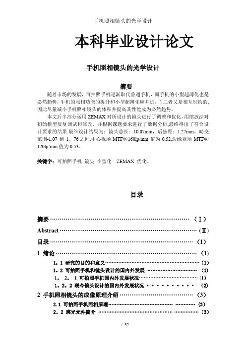
本科毕业设计论文手机照相镜头的光学设计摘要随着市场的发展,可拍照手机逐渐取代普通手机,而手机的小型超薄化也是必然趋势,手机的照相功能的提升和小型超薄化应并进,而二者又是相互制约的,因此尽量减小手机照相镜头的体积并提高其性能成为必然趋势。
本文后半部分运用ZEMAX对所设计的镜头进行了调整和优化,用缩放法对初始模型反复调试和修改,并根据课题要求进行了数据分析,最终得出了符合设计要求的结果.最终设计结果为:镜头总长:10.07mm,后焦距:1.27mm。
畸变范围-1.07到1。
76 之间.中心视场MTF@160lp/mm值为0.52.边缘视场MTF@120lp/mm值为0.53。
关键字:可拍照手机镜头小型化ZEMAX 优化。
目录摘要 (Ⅰ)Abstract (Ⅱ)目录 (1)1 绪论 (1)1。
1 研究的目的和意义 (1)1。
2 可拍照手机和镜头设计的国内外发展 (1)1。
2。
1 可拍照手机国内外发展状况 (1)1。
2。
2 现今镜头设计的国内外发展状况 (2)2 手机照相镜头的成像原理介绍 (3)2.1 可拍照手机照相原理....................................... (3)2。
2 感光元件简介............................................. (3)2。
3 镜头结构分类及选择........................... (3)2.4手机镜头的性能指标和相关术语 (4)2.4。
1镜头类型选择的依据[7] (4)2.4.2数码镜头鉴别率 (4)2。
4。
3光圈范围 (4)2. 4. 4影响像质的几个因素 (5)3光学系统设计 (6)3。
1光学设计软件简介 (6)3.1.1 ZEMAX MTF函数 (6)3。
1.2缺省的评价函数及优化 (6)3。
1. 3归一化的视场和光瞳坐标 (7)3。
2设计要求及分析 (7)3.3初始结构的选择 (8)3。
精密光学仿真实验报告

精密光学仿真实验报告实验目的:本实验旨在通过精密光学仿真,探究光的传播以及光在不同介质中的反射、折射行为,并验证光的折射定律和反射定律。
实验器材:1. 光源:使用一束激光器作为光源,确保光线的直线传播。
2. 透镜:利用凸透镜来模拟光的折射现象。
3. 平面镜:用作反射光的实验器材。
4. 介质:采用不同折射率的玻璃材料来观察光在不同介质中的折射现象。
5. 探测器:使用一台光敏探测器来接收和记录光的强度。
实验步骤:1. 设置实验平台:将光源固定在一定位置,并确保光线与探测器位置垂直。
2. 进行真空实验:将介质中的空气抽成真空状态,记录探测器接收的光强度。
3. 进行折射实验:使用不同折射率的玻璃板,记录探测器接收光线的光强度,并计算折射角度与入射角度的关系。
4. 进行反射实验:使用平面镜,记录探测器接收光线的光强度,并计算入射角度与反射角度的关系。
5. 分析实验结果:对实验数据进行分析,验证光的折射定律和反射定律,并比较实验结果与理论值的差异。
实验结果:通过实验数据的分析,我们得出了以下结论:1. 光在真空中的传播速度是恒定的,即光的速度不受介质折射率的影响。
2. 光在不同折射率的介质中发生折射时,入射角度和折射角度的正弦值之比保持恒定,即验证了光的折射定律。
3. 光在平面镜上发生反射时,入射角度和反射角度相等,即验证了光的反射定律。
4. 实验结果与理论值基本吻合,实验误差较小,说明实验方法和数据处理方法具有一定的准确性和可靠性。
实验结论:本实验通过精密光学仿真,成功验证了光的折射定律和反射定律,并得出了相应的实验结果。
该实验具有一定的教育意义和科研价值,可以帮助我们更深入地理解光的传播行为以及光在不同介质中的反射、折射现象。
高分辨率手机镜头的光学设计与性能仿真PPT课件

7
2021/7/24
镜头所匹配的芯片:
• 索尼公司HI84芯片, • 像素单元大小为1.12μm*1.12μm, • 其有效阵列尺寸3283*2471, • 成像区域大小为3678.3μm*2767.68μm。
8
镜头主要设计指标 :
2021/7/24
项目 有效焦距 视场角
F/数 场曲 相对照度 物镜距离 镜组长度 镜头结构 传感器/像素
系统结构参数表:
10
2021/7/24
Surface
Type
Object
Standard
1
Standard
Stop
Standard
3
Standard
4
Standard
5
Even asphere
6
Even asphere
7
Even asphere
8
Even asphere
9
Even asphere
10
Standard
11
Standard
Image
Standard
Radius/(mm) Infinity Infinity 1.223346
-3.107797 -1.509007 1.952723 2.619704 -1.041083 -2.586608 2.262050
Infinity Infinity Infinity
2021/7/24
14
2021/7/24
2、点列图 • 点列图反应的是整个系统成像的几何结构,其中更具有代
表意义的是 RMS 光斑,它是径向尺寸的均方根,如下图 所示,现中心视场的 RMS 直径仅为0.000875mm,小于像 素单元的大小,边缘视场也相应减小,可见系统的像差得 到了很好的优化。
光学畸变的原理及应用论文

光学畸变的原理及应用1. 引言光学畸变是指光线在经过光学系统传输过程中产生的形状失真现象。
过去几十年来,人们对光学畸变的研究已经取得了显著的进展。
本文将介绍光学畸变的原理及其在实际应用中的意义。
2. 光学畸变的分类在研究光学畸变之前,首先需要了解光学畸变的分类。
常见的光学畸变包括球差、色差、像散、弯曲畸变等。
2.1 球差球差是由于光线经过球状透镜或反射器时,不同位置的光线会汇聚或发散而产生的畸变现象。
球差的表现形式有球面像差和球面彗差。
2.2 色差色差是指不同波长的光线在通过透镜或反射器时,由于折射率的不同而引起的聚焦位置不同。
常见的色差有色像差和色散。
2.3 像散像散是指透镜或反射器在成像时,不同位置的光线所成的像位置不同的现象。
像散分为两种类型,即相对像散和绝对像散。
2.4 弯曲畸变弯曲畸变是由于光线通过球状透镜或反射器时,不同位置的光线会经历不同的折射或反射而产生的图像形状失真现象。
3. 光学畸变的原理光学畸变的原理可以用几何光学理论进行解释。
根据菲涅耳的原理和光线传播的基本规律,我们可以推导出光线在经过光学系统时产生畸变的原因。
4. 光学畸变的应用光学畸变的研究不仅仅是为了了解其原理,更重要的是为了提供解决方案,并应用于实际的光学系统中。
4.1 光学仪器设计在光学仪器的设计中,了解光学畸变的原理对于优化设计非常重要。
通过对各种畸变的研究,可以提高光学仪器的成像质量,减少畸变带来的成像失真。
4.2 光学通信在光学通信系统中,光学畸变会对信号传输造成干扰。
了解光学畸变的原理,可以帮助优化光纤的设计和信号传输过程,提高通信系统的性能。
4.3 光学成像在光学成像领域,光学畸变是一个重要的研究方向。
通过研究不同类型的光学畸变,可以改善成像系统的分辨率和清晰度,提高图像质量。
5. 结论通过对光学畸变的原理及应用的介绍,我们可以看到光学畸变在光学领域中的重要性。
光学畸变的研究对于优化光学系统的设计、提高通信系统的性能以及改善成像质量都具有重要的意义。
高分辨率手机镜头的光学设计与性能仿真外文翻译原文

Open Access Library JournalDesign of a 16.5 Megapixel Camera Lens fora Mobile PhoneYuke Ma, V. N. BorovytskyDepartment of Optical and Optoelectronic Devices, National Technical University of Ukraine, Kyiv, UkraineEmail: sherry_rain@Received 15 February 2015; accepted 2 March 2015; published 6 March 2015Copyright © 2015 by authors and OALib.This work is licensed under the Creative Commons Attribution International License (CC BY)./licenses/by/4.0/AbstractA 16.5 megapixel camera lens for a mobile phone is designed. The lens consists of 3 plastic as-pheric lenses, one glass spheric lens and an infrared glass filter. CMOS OV16850 with a pixel size of1.12 micrometers from Omni Vision is used as an image sensor. The lens has an effective focal lengthof 4.483 mm, a F-number of 2.50, a field-of-view (FOV) of 76.2 degree, and a total length of 5.873 mm.The maximum distortion of the lens is less than 2.0%. The minimum value of all field relative il-lumination is over 39.8%.KeywordsMobile Phone Camera Lens, 16.5 Megapixel Sensor, ZemaxSubject Areas: Mobile Computing Systems, Optical Communications1. IntroductionOn 7 October 2014, Omni Vision Technologies Inc. (NASDAQ:OVTI) announced a 16.5 megapixel digital im-age sensor OV16850 [1]. To design a 16-megapixel camera lens in a compact size is not a trivial task [2]. In the published papers, Song et al. (2010) [3] studied a 5 megapixel camera lens for mobile phone by a structure of 4 pieces of plastic aspheric lens. Recently, Peng (2013) [4] investigated a 8 megapixel camera lens for cell phone by using 1 glass and 3 pieces of plastic aspheric lens (1G3P) to complete the optical system. Yin et al. (2014) [5] investigated a 13 megapixel camera lens for mobile phone by choosing a 5 pieces of plastic aspheric lens (5P) structure configuration.This paper presents a detailed design of a 16.5 megapixel camera lens by a 1P1G2P lens configuration for the first time to our knowledge.Sensor OV16850 has the following specifications: pixel size of 1.12 micrometers, resolution of 5408 pixel × 3044 pixel, diagonal length of 6.95 mm or the image height, and the chief ray angle (CRA) of 33.4 degree. Ny-quist sampling frequency of the sensor can be calculated via 1000/(2 × 1.12) = 446 lp/mm. So the limited reso-Y. K. Ma, V. N. Borovytsky lution of the camera lens should be better than 446 lp/mm. An image height of 6.95 mm and a FOV of 76.2 de-gree of lens determine a focal length of 4.432 mm. We set the effective focal length (EFFL) of the lens to be less than 4.5 mm, so the total optical length (TOL) of a camera lens for a mobile phone can be confined to 5.90 mm. The specification parameters for a 16.5 M pixel mobile phone camera lens are summarized in Table 1.2. Design Method2.1. Optical MaterialsOptical resin E48R from Zeonex [6] is used in this design. The optical resin offers high transparency, low fluo-rescence, low birefringence, low water absorption, low cost, high heat resistance, and easy molding for massive production. Since the lens has a large FOV, and its high order optical aberrations such as high order spherical aberration, astigmatism, coma, high order chromatic aberrations, etc., is rather large, in order to have a more steady and clear picture, one element of the lens is set to be an aspheric glass lens, the material of the 2nd ele-ment is SF56A with a optical refractive index of 1.785 and a dispersion coefficient of 26.08, the first, the third and the fourth element of the lens are chosen to be E48R, whose optical refractive index is 1.531 and the cor-respondent dispersion coefficient is 56.0, the fifth element is an infrared filter (IR), and the last is a cover glass BK9.2.2. Design ProceduresZemax [7] is used to simulate the lens optical system. Considering low price and massive production, an initial configuration 1P1G2P of the lens is chosen for the design by trial and error process. There are 6 elements in this lens, the first to the fourth element is the aspheric lens respectively, the fifth element is an IR filter and the sixth is a glass cover of the sensor. All the surfaces of the element 1 to 4 are set to even aspheric profiles, the fifth and the sixth elements are plane. Radius, thickness of each surface from 1 to 8 is set to be variable, all surface conic constants as well as aspheric coefficients are set to be variable either.2.3. Optimization ProceduresThe optimization procedure includes three steps.Step 1 1) Using operand EFFL to define the effective focal length of the lens, using operand TOTR to confine the total optical length of the lens system, using operand RAID to confine the CRA, using operand REAY to de-fine the image height; 2) The merit function also consisted of operands MNCA, MXCA and MNEA to define the air thickness and air boundary constrains, meanwhile operands MNCG, MXCG and MNEG are used to glass case either; 3) Initially, operand LONA is used to control the spherical aberration, LACL is used to control the lateral color for this focal system. TRAY and SUMM are used to control the coma, and operand DIMX is used to control the distortion of each field of view; 4) Using operand TRAY, DIFF, RAGC, ACOS and TANG to control tangential curvature; 5) Using operand TRAY, DIFF, RAGC, ACOS, TANG, CONS and PROD to con-trol sagittal curvature; 6) Operand TRAC is used to control the spot size of each field of view for the whole wa-velength.Step 2 After the initial optimization, high order controlling operands are added in the merit function, i.e., 1) Using operand TRAY, RAGC, ACOS, TANG, DIVI and DIFF to control the axial and longitudinal chromatic aberrations; 2) Using operand TRAY, RAGC, ACOS, TANG, DIVI, CONS, PROD and DIFF to control the high order spherical aberration; 3) Using TRAY, DIVI and DIFF to control the high order chromatic spherical aber-ration; 4) Using FCGT, FCGS, DIFF and SUMM to control the astigmatism.Step 3 Siedel coefficients are observed after each optimization completed, the layout is watched to show a reasonable configuration. At last, 1) Both MTFS, MTFT is added to the merit function to improve the lens reso-lution; 2) Meanwhile TRAC is replaced by operand OPDX; 3) Weight in merit function is always ready to change to optimize some heavy contribution items in order to get a reasonable lens configuration.Table 1.The specification parameters for a mobile phone camera lens of 16.5 megapixels.EFFL TOL FOV F-number Image height CRA Relativeillumination distortionBack focal length<4.5 mm <5.9 mm 76.2 degree 2.50 >6.95 mm <33.4 degree >35% <2% >0.2 mmY. K. Ma, V. N. Borovytsky3. ResultsThe optimized lens configuration is shown in Figure 1, the correspondent lens data are listed in Table 2 and Table 3. The lens has a total track of 5.873 mm, with an effective focal length of 4.483 mm, and of a back focal length 0.207 mm. The lens has a FOV of 76.2 degree, the image height is 6.97 mm which is a little larger than the CMOS sensor size and implies an easy installation of the CMOS sensor to the lens module. The CRA is less than 33.4 degree; a good coupling between the optics and the COMS is expected.The Spot Diagram, MTF, curvature and distortion, lateral color, chromatic focal shift, and relative illumina-tion can be used to evaluate the lens design. The RMS radius of spot size shall be less than three times of the pixel size (Yu [8]), to this design, it is 3.36 micrometer. The RMS spots of all fields are shown in Figure 2. The RMS spot radius of fields 1 - 6 (FOV 0.000 to FOV 0.787) is 2.545 μm, 2.761μm, 2.662μm, 2.856 μm, 2.337 μm, and 2.091μm respectively, much less than the imaging needs of the CMOS sensor, meanwhile the radius of spot size of field 7 (FOV 0.92) is 5.641 μm and that of field 8 (FOV 1.0) is 4.985μm, very close to this need, that is to say that the whole FOV can image very clearly.Table 2. Lens configuration data.Surf: type Radius Thickness Glass Semi-diameter Conic OBJ Standard Infinity Infinity Infinity 0.000STO Even asphere 3.134 1.413 E48R 1.077 4.1312 Even asphere −3.115 0.021 1.233 1.6043 Spheric −2.252 0.445 SF56A 1.219 0.0004 Spheric −9.057 0.512 1.346 0.0005 Even asphere −4.306 1.378 E48R 1.409 4.8686 Even asphere −2.443 0.938 1.823 −1.2047 Even asphere −2.310 0.354 E48R 2.167 −8.7898 Even asphere −5.332 0.300 3.174 1.6419 Standard Infinity 0.313 BK7 3.222 0.00010 Standard Infinity 0.200 3.344 0.000IMA Standard Infinity 3.485 0.000 Table 3. Aspheric coefficients of each correspondent surface. Aspheric coefs A B C D E F G HSTO Evenasphere 0.050 −0.015 −5.30E-003 −3.136E-003 −3.048E-003 0.000 0.000 0.0002 Evenasphere −0.043 −0.015 −0.012 3.559E-003 −2.045E-003 0.000 0.000 0.0003 Evenasphere 0.000 0.000 0.000 0.000 0.000 0.000 0.000 0.0004 Evenasphere 0.000 0.000 0.000 0.000 0.000 0.000 0.000 0.0005 Evenasphere 0.093 −0.033 −1.072E-003 −3.462E-003 −4.413E-004 0.000 0.000 0.0006 Evenasphere −0.060 9.480E-003 −2.006E-003 −9.711E-004 −1.576E-004 1.665E-003 0.000 0.0007 Evenasphere −0.101 −6.280E-003 1.653E-003 −1.796E-003 3.519E-004 4.051E-005 −9.441E-006 0.0008 Evenasphere 0.196 −0.012 1.030E-003 3.686E-007 −1.956E-006 −4.296E-007 5.719E-008 −3.874E-010Y. K. Ma, V. N. BorovytskyFigure 1. 16.5 M pixels mobile phone camera lens layout.Figure 2. 16.5 M pixels mobile phone camera lens spot diagram.Y. K. Ma, V. N. Borovytsky MTF is a comprehensive standard to evaluate the imaging nature of a lens. In this design, the MTF value of central field at 223 lp/mm is 53.4% and 21.4% at 446 lp/mm. For FOV 0.8 zone, MTF value at 223 lp/mm is more than 37.6% in sagittal plane and more than 32.6% in tangential plane, at 446 lp/mm, MTF value is more than 14% in sagittal plane and more than 2% in tangential plane. The MTF curve is shown in Figure 3.The curvature and distortion of the lens is shown in Figure 4; it is shown in Figure 4 that the lens has a low field curvature; it is within 0.05, much less than the imaging need 0.1, and the distortion is less than 2%. It meets the design need.Figure 3.16.5 M pixels mobile phone camera lens MTF curve.Figure 4. Field curvature and distortion of a 16.5 M pixels mobile phone camera lens.Y. K. Ma, V. N. Borovytsky Both the lateral color and chromatic focal shift of the lens revealed a nearly diffraction limited design of this 16.5 M pixels mobile phone camera lens. They are shown in Figure 5 and Figure 6 respectively. In Figure 5, the lateral color of the maximum field is within the Airy disk which implies a diffraction limited design.It is also indicated in Figure 6that the chromatic focal shift of the lens is within diffraction limited. Relative illumination of the lens should be checked; it is shown Figure 7. It can be found in Figure 7that the minimum of the relative illumination value is 40%. Both an auto gain controlling circuit and an auto balance controlling circuit can keep a uniform brightness of the image. It is concluded that this design of a 16.5 M pixels mobile phone camera lens can meet the design needs.Figure 5.The lateral color of a 16.5 M pixels mobile phone camera lens.Figure 6.Chromatic focal shift of a 16.5 M pixels mobile phone camera lens.Y. K. Ma, V. N. BorovytskyFigure 7.Relative illumination of a 16.5 M pixels mobile phone camera lens.At last, a tolerance analysis was made and the results show that a 5 μm deviation in radius, thickness, a 10μm deviation in decenter, and a 0.2 degree in tilt are permitted. It is also shown in Table 2 that the smallest thick-ness of the plastic piece is 0.354 mm which means that a precision injection molding for massive production of the plastic lens elements can be expected. The glass element for this design is set to be a standard spheric surface for an easy production consideration.In conclusion, this 16.5 M pixels mobile phone camera lens is a practical design.4. ConclusionBy using Zemax, a 16.5 M pixels mobile phone camera lens is designed. The lens consists of 3 plastic aspheric lenses, one glass spheric lens and an infrared glass filter. OV16850 whose pixel size of 1.12 micrometer from Omnivision is used as a image sensor. The lens has an effective focal length of 4.483 mm, a F-number of 2.50, a field-of-view (FOV) of 76.2 degree, and a total length of 5.873 mm. This is a practical design for a 16.5 M pix-els mobile phone camera lens.References[1]Geary, J.M. (2002) Introduction to Lens Design with Practical Zemax Example. Willmann-Bell Inc., Richmond.[2]Zhang, P., et al. (2009) Design of a 5 Megapixel Mobile Phone Camera Lens. Journal of Applied Optics, 30, 934-938.[3]Song, D.F., et al. (2010) Design of Lens for 5 Mega-Pixel Mobile Phone Cameras. Journal of Applied Optics, 31, 34-38.[4]Peng, X.F. Design of High Pixel Mobile Phone Camera Lens. Research Journal of Applied Sciences, Engineering andTechnology, 6, 1160-1165.[5]Yin, Z.D., et al. (2014) Optical Design of a 13 Megapixel Mobile Phone Camera Lens. Laser & Optoelectronics Progress,51, 163-168.Y. K. Ma, V. N. Borovytsky[6]World’s Foremost Optical Polymer for Precision-Molded Optics. /optics.aspx[7][8]Yu, D.Y. (1999) Engineering Optics. China Mechanical Press, Beijing.。
- 1、下载文档前请自行甄别文档内容的完整性,平台不提供额外的编辑、内容补充、找答案等附加服务。
- 2、"仅部分预览"的文档,不可在线预览部分如存在完整性等问题,可反馈申请退款(可完整预览的文档不适用该条件!)。
- 3、如文档侵犯您的权益,请联系客服反馈,我们会尽快为您处理(人工客服工作时间:9:00-18:30)。
高分辨率手机镜头的光学设计与性能仿真- 毕业设计论文郑州轻工业学院本科毕业设计, 论文,题目高分辨率手机镜头的光学设计与性能仿真学生姓名专业班级电子科技13-01学号院(系)物理电子工程学院指导教师(职称)完成时间2017 年5月30日目录中文摘要英文摘要1 绪论1.1 引言1.2 手机镜头与数码相机镜头比较1.3 拍照手机国内外发展状况1.4 手机镜头未来趋势手机照相理论基础2.1 手机镜头成像原理2.2 手机镜头基本术语2.2.1 焦距62.2.2 光圈7 I2.2.3 像素2.2.4 分辨率3 手机镜头像差理论与优化设计致谢 参考文献高分辨率手机镜头的光学设计与性能仿真摘要快速发展的手机照相功能,让我们对照片的清晰度要求越来越高,一些低端的数码相机早已逐步由拥有高分辨率的手机摄像头逐渐取代了,但在目前市场照相手为这样,对研究高分辨率手机镜头有着重大的意义。
文章中总结了手机镜头的国内 外发展的基础上,结合了光学非球面以及像差理论,使用ZEMA )软件,进行光学设 计得到了一个 800 万像素的超薄手机镜头。
该镜头由 4片光学塑料非球面透镜组 成,优化是通过ZEMA )软件的功能,并最终获得一个高像素超薄成像结构,总长仅3.21mm 且具有优良性能、成本低廉,满足设计要求的手机镜头。
关键词:手机镜头;800万像素;塑料非球面;ZEMAX3.1 手机镜头像差理论3.2 光学系统的优化设计11 4.1 4.2 百万像素手机镜头光学系统设计镜头设计指标设计结果13 1313 1819 机中高像素拍照手机的占绝大部分, 800万像素的手机在市场中高比率占有正式因2.2.2 光圈7OPTICAL DESIGN AND PERFORMANCE SIMULATION OF IHIGH RESOLUTION MOBILE PHONE LENSABSTERACTThe rapid development of mobile phone camera function, so that we are more and more demanding on the photos, some low-end digital camera has long been gradually replaced by a high-resolution mobile phone camera, but in the current market camera phone high pixel camera phoneOf the vast majority of the 8 million pixel mobile phone market in the high proportion of possession of the formal because of this, the study of high-resolution mobile phone lens has great significance. The article summed up the development of mobile phone at home and abroad on the basis of the combination of optical aspheric and aberration theory, the use of ZEMAX software, optical design has been a 8 million pixel ultrathin mobile phone lens. The lens consists of four optical plastic aspherical lenses that are optimized by the function of the ZEMAX software and eventually get a high pixel ultra-thin imaging structure with a total length of only 3.21mm and with excellent performance, low cost to meet the design requirements of the phone lens.KEY WORDS mobile phone lens; eight million pixels; plastic aspheric;ZEMAXII1 绪论1.1 引言在当今社会, 手机已成为人们日常生活的必需品。
手机作为最基本的通信手段之一, 已经被赋予了更多的实用功能,摄像机的性能已经成为衡量手机综合性能的重要标准。
现在的手机已经拥有高端镜头和入门级数码相机可以媲美摄影成像性能但随着微型光学镜头和图像处理技术的发展, 手机彩信和移动互联网技术的不断涌现, 实时记录手机独特的快速共享功能是一大亮点, 人们喜欢用手机进行记录美好的瞬间和实时图像,并与朋友和家人共享实时。
因此, 为了获得更好的拍摄效果和质量人们也是不断地开发与研究, 研制高像素手机镜头已经成为一种趋势。
成像质量高、便携性好的手机摄像头将越来越普及。
随着手机和手机摄像头镜片加工技术的突破, 随着光学加工、精密机械和电子电路技术的不断发展与更新, 一些低端的数码相机被手机取代, 和一些高质量的影像如数码相机也已经被高像素镜头的手机取代。
单反相机,价格更昂贵,且操作复杂,体积和重量让他无法被复制。
相比之下, 高像素手机正成为首选。
目前市面上800万像素以下的手机占据了大部分市场, 画面质量并不理想, 因此设计高质量的成像,简单的手机镜头结构显得尤为迫切和重要。
1.2 手机镜头与数码相机镜头比较现在几乎所有的手机都有摄像头, 同时, 手机摄像头会迅速改变。
如手机的数码相机功能, 它的卖点不是数码相机的功能, 是在给定的MMS 无线传输、实时共享等特点。
[1] 但进入3G 时代以来, 充分证明手机在人们进行视频通话的功能是非常有前途的, 和朋友从简单的语音通话到视频通信, 它更能吸引消费者,手机摄像头可以实现数字图像通信是基于数码相机完全无法匹敌的。
移动摄像机镜头和数码相机镜头的特点和结构有许多不同之处, 可以从以下几个方面进行比较:(1) 侧重点不同移动相机镜头专注于如何最好的成像性能可以实现在有限的长度范围内。
是微透镜的主要追求 , 保证图像质量的前提下 , 缩短光学镜头的最大总长度,数码 相机镜头的总长度是没有那么严格 , 可以把体积和空间做的比较大 ,它是图像质量的主要追求 , 如何得到图像的高质量是关注的焦点。
(2) 镜片的数目不同手机相机镜头紧凑 , 这限制了透镜的数目 , 他们大多是 4 片左右。
为了提高数码相机的成像质量 ,更多的镜头可以不受限制地使用 , 这更有利于提高图像质量 以数码相机的镜头一般超过 5 片。
(3) 加工难度不同手机相机通常使用塑料非球面 , 近年来 ,中国的塑料加工技术的非球面零件[2] 大的进步 , 但还没有形成一个成熟的、完整的系统。
普通数码相机的使用玻 璃球面具有性能稳定、技术成熟、易于加工。
会使用更多的非球形玻璃高端数 相机因为在球面像差的光学设计 , 彗差 , 散光和畸变,像差校正、非球面表面 有更好的效果。
可以有效地改善图像质量 , 减少光学元件的数量 , 大大减轻摄像机的 重量。
(4) 光敏元件不同目前市场上有两种光敏元件 。
一个是 CCD 器件的电荷耦合器件 , 价格比较昂贵,[3] 但技术成熟,灵敏度高,噪声低,成像效果好。
另一个是CMOS 互补金属氧化物半导体 ,其制造成本相对较低 , 功耗小 , 集成度高 。
光敏元件通常用来移动照 相机镜头。
在数码相机的发展中 , 光敏元件的面积不能占太多 , 但在追求更好的成像 , 更好利用纯彩色屏幕。
感光元件比较大 , 数码单反的应用基本上是一个光敏元件的APS 规格,, 在高端机器中 ,必须使用全帧传感器。
但这是不可想象的 , 因为它必然会 增加产品的体积 , 近几年,所 往往[4] 来,随着CMOS:艺的发展,Exmor RCMOS的出现,CMOS传感器克服了许多技术瓶颈,手机镜头使用CMOS图像传感器集成度高的多。
因此,照相手机有以下优点:1. 便携性好,随时携带使用;2. 实时共享,高效快捷;3. 质量稳定、重塑画面;4. 体积小、耗电量小、结构紧凑。
1.3 拍照手机国内外发展状况手机或相机的起源始于2000 年, 那时日本的第三大移动运营商J-Phone 推出了世界上第一个j-sh04 手机内置相机,它配备了11万像素CMO数码相机的镜头,并配有一个大镜子,能够拍摄355 x 288 像素的照片,虽然画面太差,而且无法与主流配置相比,许多消费者感觉需求量不大的,但它是有照相功能手机的一个里程碑,它使手机相机的快速发展,它的出现,手机厂商已逐渐认识到手机镜头存在价值。
在接下来的两年或三年, 如手机摄像头像素也如雨后春笋, 一场春雨后有所增加, 如索尼P900,有了镜头,你可以⑸拍摄640X 480像素,最大分辨率为30万。
虽然这些镜片的质量略有改善,而且价格低,开发周期短,但仍远远低于入门级数码相机, 后来也更多地用于低端相手机的第二摄像头。
2003五月,夏普公司重新推出的第一个百万像素摄像头的手机j-sh53,,它有[6]100万像素的摄像头,最大分辨率为1144 * 858像素。
除了支持多种分辨率选择和连续的功能,在j-sh04第一代手机质量的变化,无论是拍摄的清晰度、亮度和色彩还原,接近低端数码相机的水平。
接下来的几天中,技术不再是手机摄影像素的瓶颈,同年十月,日本卡西欧运营商KDDI定制的世界上第一个200万像素的摄像头a5403ca 手机,该机采用光敏元件在暗光条件下也CCD表现出色,并支持自动对焦和闪光灯拍摄,它的出][7现,被称为手机行业的影像学变化的革命。
2004年初,富士通生产的f900i拥有128万像素CCD镜头,11万像素CMO镜头,两个摄像头可用于视频通话。
同年5月,和卡西欧的冲击,推出了世界上300万像素的摄像头,a5406ca第一手机,它配备了320万英寸的大尺寸CCD感光元件的1 / 1.8 有效像素,照片QXGA(2048x153像素)可以采取,而非球面镜片的小而薄的。
有利于提高图像质量也降低了系统结构大小。
从世界上第一个手机百万像素的诞生,到第一个300万像素手机摄像头,只有大约一年的时间,手机摄像头在这个时期是塑料镜头结构3片,与像素数、光学非球面逐渐增大。
图1-1为3芯片的手机镜头的周期结构显示,3个镜头和过滤器和玻璃盖,其中非球面光学元件数量已达到4-5个,市场较在45 - 50 度角,光敏元件的尺寸为1/ 4英寸,最小像素尺寸可为[8] 1.75mm x 1.75m m但基本上没有自动对焦或变焦功能。