nec投影机说明书
NECMT850单枪投影机操作手册
NEC MT850單槍投影機操作手冊一、投影機外觀及操作說明二、遙控器外觀及操作說明三、投影機與電腦連接說明四、投影機與錄影機連接說明五、簡易操作說明六、維護注意事項一、投影機外觀及操作說明※ 注意事項1.旋轉調整腳架可改變投影機投射角度。
2.畫面模糊可旋轉焦距轉軸以改善。
3.移動縮放畫面轉軸可放大縮小畫面。
遙控發射端功能鍵USB 滑鼠插座縮放畫面 焦距遙控發射端 空氣濾清器鏡頭蓋電源插孔 調整腳架鏡頭PC 卡插槽影音信號端子位置手提把遙控發射端燈罩燈罩螺絲遙控發射端 喇叭喇叭空氣濾清器後腳架後腳架影音信號端子位置說明影音輸出端子影音輸入端子1影音輸入端子2S-VIDEO視訊聲音輸入端子VIDEO視訊輸入端子*注意事項1.當電腦要連接投影機時,電腦的螢幕線必須接至RGB INPUT1或RGBINPUT2。
通常接至RGB INPUT1即可,如果是連接至RGB INPUT1,那麼影像來源也要選擇RGB1才行,切記!2.當錄影機要連接投影機時,影像信號線接至VIDEO ,聲音信號線則接至L/MONO及R。
※功能鍵區操作說明1.視訊來源選擇鈕(SOURCE)可自動搜尋你的視訊影像來源。
2.畫面調整鈕(AUTO ADJUST)自動調整畫面的位置到中央。
3.選單鈕(MENU)顯示選單,進行設定。
4.選擇鈕(SELECT)根據箭頭的位置可移動方向。
5.執行鈕(ENTER)6.取消鈕(CANCEL)7.運轉狀態燈號(STATUS)8.電源燈號(POWER)9.電源鈕(ON/STAND BY)如果要關閉電源,必須持續按兩秒才能關閉。
二、搖控器外觀及操作說明11.遙控發射端2.雷射光筆發射端3.指示燈按下任何按鈕,指示燈都會閃爍。
4.電源啟動鈕(ON)5.電源關閉鈕(OFF)必須持續按兩秒才能關閉。
6.視訊選擇鈕(VIDEO)按下此按鈕可選擇你的視訊影像來源。
如:錄放影機、VCR、DVD player等。
7.S-Video選擇鈕(S-Video)按下此按鈕可選擇你的S-Video視訊影像來源。
NEC PX1005QL 投影仪安装指南说明书
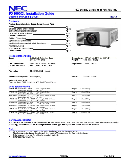
ContentsProduct Description, Lens Specs, Screen/Aspect RatioNotes Pg 1Distance Charts and Formulas Pg 2-3Ceiling Mount/Desktop Installation Pg 4Lens Shift Adjustable Range Pg 5Cabinet Dimensions Pg 6Cabinet Dimensions Pg 7Optional Lens Dimensions Pg 8Ventilation Requirements/Portrait Requirements Pg 9Regulatory Labels Pg 10Input Panel and Button Panel Pg 11Control Codes Pg 12Product DescriptionType: 1 chip DMD Reflection Type Dimensions: 19.7” (W) x 8.49” (H) x 23.0” (D)0.66 in. TRP DMD Weight: 68.8 lbs. / 31.2kgDMD Resolution: 2716 x 1528 (16:9) WQXGA Brightness: 10,000 LumensOutput Resolution:3840 x 2160 (16:9) UHDFan Noise: 42 dB / 39dB @ 1 meterPower Consumption: 1222W (max) BTU’s: 4166 BTU/hourNetwork Ready, RJ45Powered: Lens Shift, Horizontal & Vertical /Zoom/ FocusLens SpecificationsNP39ML-4K: Throw Ratio: ~ 0.38:1 Focal Length: 11.4mm Weight: 6.0lbs. / 2.7kgScreen Sizes: 85”-350”F/#: 1.85NP16FL-4K:Throw Ratio: ~ 0.76:1 Focal Length: 11.6mm Weight: 3.3lbs. / 1.5kgScreen Sizes: 50”-300”F/#: 1.85NP17ZL-4K:Throw Ratio: 1.24 - 1.78:1 Focal Length: 18.7 – 26.5mm Weight: 2.0lbs. / 0.9kgScreen Sizes: 50”-300”F/#: 1.85NP18ZL-4K:Throw Ratio: 1.71 – 2.25:1 Focal Length: 26.0 – 34.0mm Weight: 2.4lbs. / 1.1kgScreen Sizes: 50-300”F/#: 1.70-1.90NP19ZL-4K:Throw Ratio: 2.20 -3.67:1 Focal Length: 32.9 – 54.2mm Weight: 1.9lbs. / 0.84kgScreen Sizes: 50-300”F/#: 1.86 – 2.48NP20ZL-4K:Throw Ratio: 3.54 – 5.36:1 Focal Length: 52.8 – 79.1mm Weight: 2.2lbs. / 1.0kgScreen Sizes: 50”-300”F/#: 1.85-2.41NP21ZL-4K: Throw Ratio: 5.25 – 8.28:1 Focal Length: 78.5 -121.9mm Weight: 2.2lbs. / 1.0kgScreen Sizes: 50”-300”F/#: 1.85-2.48NP31ZL-4K: Throw Ratio: 0.74 – 0.93:1 Focal Length: 11.3 -14.1mm Weight: 3.1lbs. / 1.4kgScreen Sizes: 50-300”F/#: 1.96-2.3Screen/Aspect Ratio4:3, 16:9 and 16:10 screens are fully supported with proper aspect ratio control for both type sources using NEC developed scaling technology. Menu selections have settings for each screen type and aspect ratio control for each source type.Notes▪For screen sizes not indicated on the projection tables, use the formulas below.If the figures on the tables do not match the results of formulas, use the figures in the table.▪Distances are in inches, for millimeters multiply by 25.4.▪Distances may vary 5%.Formulas: 16:9 Aspect Ratio (UHD)The Projection Formulas use the image width for calculation. Image width is the same for all aspect ratios, only vertical image size varies. For proper projector placement, determine the image width for a desired screen size. Use the Screen Formulas below to calculate all screen dimensions. Plug in the image width for “W” in the Projection Formulas.Refer to the diagrams and charts for popular screen sizes on page 2 and 3:Projection Formulas:Definitions: 16:9 Screen FormulasNP16FL-4K: C = 0.794W – 1.85W = Image Width W = H x 16/9NP17ZL-4K: C(Wide) = 1.269W – 2.091 ------ C(Tele) = 1.802W – 1.910 H = Image Height (size) H = W x 9/16NP18ZL-4K: C(Wide) = 1.748W – 2.673 ------ C(Tele) = 2.290W – 2.633 C = Throw distance Screen Diagonal = W x 18.358/16 NP19ZL-4K: C(Wide) = 2.241W – 3.150 ------ C(Tele) = 3.713W – 3.114NP20ZL-4K: C(Wide) = 3.618W – 5.319 ------ C(Tele) = 5.434W – 5.299NP21ZL-4K: C(Wide) = 5.412W – 11.622 ---- C(Tele) = 8.438W – 11.531NP31ZL-4K: C(Wide) = 0.768W – 1.795 ------ C(Tele) = 0.953W – 1.705NP39ML-4K:Ultra-Short Throw lens (See page 3 for Formulas)Distance ChartFormulas: 16:9 Aspect Ratio (UHD)The Projection Formulas use the image width for calculation. Image width is the same for all aspect ratios, only vertical image size varies. For proper projector placement, determine the image width for a desired screen size. Use the Screen Formulas below to calculate all screen dimensions. Plug in the image width for “W” in the Projection Formulas.Refer to the diagrams and charts for popular screen sizes on page 2 and 3:Projection Formulas:Definitions: 16:9 Screen FormulasNP39ML-4K: A=C-33 .0 W = Image Width W = H x 16/9B=0.588*W H = Image Height (size) H = W x 9/16C=(0.351*W)+2.362 C = Throw distance Screen Diagonal = W x 18.358/16D=E-8.5E=0.310*WNP39ML-4 InstallationCeiling Mount InstallationNote:Lens Shift Feature is not available for the NP16F-4K L.This lens should only be used for “zero degree”/”no-offset” applications.Lens Shift Adjustable RangeDesktop and Ceiling MountRev 1.4Cabinet DimensionsThe following diagrams show the cabinet dimensions for the PX1005QL. Dimensions are in inches. For millimeters multiply by 25.4. Note: Dimensions below shown without a lens22.6522.899.829.8219.638.314.468.49INTAKE I N T A K EEXHAUST LENS RELEASE BUTTONDesktop and Ceiling MountRev 1.4Cabinet Dimensions6-M4 (Max. M4 x 16)5.125.905.90 3.9111.801.5816.51 1.582.3419.061.51Desktop and Ceiling MountRev 1.4Optional Lens DimensionsNP16FL-4KNP17ZL-4KNP18ZL-4KNP19ZL-4KNP20ZL-4KNP39ML-4KNP31ZL-4K 1.36NP21ZL-4KDesktop and Ceiling Mount Rev 1.4 Ventilation Requirements∙If there are walls on boths sides of the projector :∙If there’s a wall behind the projector :Portrait RequirementsDesktop and Ceiling Mount Rev 1.4 Regulatory LabelsDesktop and Ceiling Mount Rev 1.4 Input PanelControl PanelDesktop and Ceiling Mount Rev 1.4 PC Control CodesFunction Code DataPOWER ON 02H 00H 00H 00H 00H 02HPOWER OFF 02H 01H 00H 00H 00H 03HINPUT SELECT HDMI 1 02H 03H 00H 00H 02H 01H A1H A9HINPUT SELECT HDMI 2 02H 03H 00H 00H 02H 01H A2H AAHINPUT SELECT DisplayPort 1 02H 03H 00H 00H 02H 01H A6H AEHINPUT SELECT DisplayPort 2 02H 03H 00H 00H 02H 01H A7H AFHINPUT SELECT HDBaseT 02H 03H 00H 00H 02H 01H 20H 28HINPUT 3G SDI1 02H 03H 00H 00H 02H 01H C4H CCHINPUT 3G SDI2 02H 03H 00H 00H 02H 01H C5H CDHINPUT 3G SDI3 02H 03H 00H 00H 02H 01H C6H CEHINPUT 3G SDI4 02H 03H 00H 00H 02H 01H C7H CFHINPUT SELECT SLOT 02H 03H 00H 00H 02H 01H ABH B3HPICTURE MUTE ON 02H 10H 00H 00H 00H 12HPICTURE MUTE OFF 02H 11H 00H 00H 00H 13HCable ConnectionCommunication Protocol:Baud Rate: 38400 bps (for cable lengths longer than 20’, it is recommended changing to 9600 bps in setup menu) Data Length: 8 bitsParity: No ParityStop Bit: One bitX on/off: NoneCommunications: Full duplexPC Control Connector (D-Sub 9P)Note 1 : Pins 1, 4, 6, and 9 are used inside the projector.Note 2: For long cable runs it is recommended to set communication speed within the projector to 9600 bps.Note 3: Jumper “Request to Send” and “Clear to Send” together on both ends of the cable to simplify cable connection.。
NEC MultiSync EA系列LED背光LCD显示器产品介绍说明书

Business DesktopNEC MultiSync® EA SeriesHigh-performance, LED-backlit LCDdisplays ideal for corporate environmentsHighlights•LED backlight technology provides for industry-leading low power consumption and less hazardous materials •iF Product Design Award for 2012 bestowed upon the 27” MultiSync EA273WM•Four-way ergonomic stand boasts pivot, tilt, swivel and height adjustment up to 130mm to maximize your viewing comfort •Touch-sensitive OSD® controls are integrated into the bezel, making display adjustments easier than ever •Integrated 4-port USB 2.0 hub easily connects you to your peripherals•Comprehensive input panel , including DisplayPort, HDMI, DVI-D and 15-pin VGA, connects you to the latest peripherals andfuture-proofs your investment•Space saving, multimedia speakers , which enhance your computing experience, are hidden to maintain the monitor’s aesthetic appeal (headphone jack also included)•ControlSync enables multi-monitor setups of up to six monitors and controls up to 26 settings•Customize Setting allows both users and IT administrators to set and restore preferred settings with just one touch, contributing to a free-seating business environment•Smart sensing technology includes ambient light and human sensors, which considerably reduce power consumption by automatically detecting your work conditions and adjusting to the proper display brightness or entering Power Saving Mode •Carbon footprint meter helps track and calculate the reduction of green gas emissions, while the resettable cost meter (via On Screen Display) indicates electricity cost savings based on currency settings•NaViSet™ software offers an intuitive graphical interface, allowing for easy adjustment of display settings via mouse and keyboard. NaViSet Administrator provides all the advanced control to remotely located IT professionals.•EPEAT Silver/Gold compliance ensures the displays reduce hazardous waste and electricity usage, resulting in lower energy costs and increased protection for the environment•ENERGY STAR® compliance reduces electrical costs and lowers total cost of ownershipReimagine your desktop computing experience. With its next generation MultiSync EA Series, NEC has developed monitorsolutions that push the boundaries of what you’ve come to know as business-grade screen performance. The 22” MultiSync EA224WMi, 22” EA223WM, 23” EA234WMi, 24” EA243WM and EA244WMi, 27” EA273WM, and 29” EA294WMi deliver a completely redesigned chassis with a host of enhanced features, advanced technologies, future-proof connectivity and environmentally friendly benefits. Select models tout an IPS module, which boasts the best possible color accuracy and minimal viewing angle shift.These models boast LED backlight technology, which not onlyreduces power by up to 52% compared to their predecessors, but leads to a 30% thinner and 25% lighter chassis. Other green features include ECO Mode™, a carbon footprint meter and an ambient light sensor, which automatically adjusts the brightness to the optimal setting depending on ambient lighting, screen content or both, conserving power up to 87% compared to typical energy consumption. In addition, the human sensor detects user activity in front of the monitor and reduces display power up to 95% with inactivity.The ground breaking ControlSync™ feature allows users to control up to six next-generation MultiSync EA Series units in a multi-monitor configuration. Upon establishing one unit as the master, you will be able to simultaneously control manyperformance attributes of the multi-monitor setup through the master monitor.22" | 23" | 24" | 27" | 29”NEC Display Solutions500 Park Boulevard, Suite 1100Itasca, IL 60143866-NEC-MOREMultiSync is a registered trademarks and ECO Mode and ControlSync are trademarks of NEC Display Solutions. All other brand or product names are trademarks or registered trademarks of their respective holders. Product specifications subject to change.©2013 NEC Display Solutions of America, Inc. All rights reserved.25.NEC.80.GL.UN.029 rev 071220134-way adjustable standAmbient and human sensorsComprehensive input panel (select models)Touch-sensitive OSD controls Thin, lightweight designwith integrated/hidden speakersUSB 2.0 hub。
NEC 液晶投影机控制命令参考手册说明书
Projector Control Command Reference ManualIntroductionThis manual describes the commands used to control an NEC-made projector from a PC or other external device. A projector can be controlled by exchanging commands with an external device connected via a serial port or network.The manual assumes basic knowledge of projectors. For information about the functions of the model in use and how to adjust the device, see the operation manual of the projector .For information about the connection between the projector and an external device, see "1 Connecting an External Device" (page 5). Connect an external device as appropriate for the usage environment of the projector.Models for which the control commands are availableSee the Appendix "Connecting an External Device".ConventionsFor information about how commands and responses are expressed in this manual, see "2.1 Understanding command details" (page 10).NOTES1. The acts of disclosure, duplication, and modification of part or whole contents in this reference manual withoutpermission are prohibited.2. The contents of this reference manual are subject to change without notice.3. Great care has been taken in the preparation of this reference manual; however, should you notice anyquestionable points, errors or omissions, please contact us.4. Notwithstanding article 3. NEC will not be responsible for any claims on loss of profit or other matters deemed toresult from using this reference manual.ContentsProjector Control Command Reference Manual (1)Introduction (2)Contents (3)1.Connecting an External Device (5)1.1Connection interface (5)1.2Communication conditions (7)mand List (8)2.1Understanding command details (10)2.2Parameters (10)2.3Responses (11)2.4Error code list (12)mand details (13)3.1[ 009. ERROR STATUS REQUEST ] (13)3.2[ 015. POWER ON ] (15)3.3[ 016. POWER OFF ] (16)3.4[ 018. INPUT SW CHANGE ] (17)3.5[ 020. PICTURE MUTE ON ] (19)3.6[ 021. PICTURE MUTE OFF ] (20)3.7[ 022. SOUND MUTE ON ] (21)3.8[ 023. SOUND MUTE OFF ] (22)3.9[ 024. ONSCREEN MUTE ON ] (23)3.10[ 025. ONSCREEN MUTE OFF ] (24)3.11[ 030-1. PICTURE ADJUST ] (25)3.12[ 030-2. VOLUME ADJUST ] (27)3.13[ 030-12. ASPECT ADJUST ] (29)3.14[ 030-15. OTHER ADJUST ] (30)3.15[ 037. INFORMATION REQUEST ] (32)3.16[ 037-3. FILTER USAGE INFORMATION REQUEST ] (33)3.17[ 037-4. LAMP INFORMATION REQUEST 3 ] (34)3.18[ 037-6. CARBON SAVINGS INFORMATION REQUEST ] (36)3.19[ 050. REMOTE KEY CODE ] (38)3.20[ 051. SHUTTER CLOSE ] (40)3.21[ 052. SHUTTER OPEN ] (41)3.22[ 053. LENS CONTROL ] (42)3.23[ 053-1. LENS CONTROL REQUEST ] (44)3.24[ 053-2. LENS CONTROL 2 ] (46)3.25[ 053-3. LENS MEMORY CONTROL ] (48)3.26[ 053-4. REFERENCE LENS MEMORY CONTROL ] (50)3.27[ 053-5. LENS MEMORY OPTION REQUEST ] (52)3.28[ 053-6. LENS MEMORY OPTION SET ] (53)3.29[ 053-7. LENS INFORMATION REQUEST ] (55)3.30[ 053-10. LENS PROFILE SET ] (56)3.31[ 053-11. LENS PROFILE REQUEST ] (57)3.32[ 060-1. GAIN PARAMETER REQUEST 3 ] (58)3.33[ 078-1. SETTING REQUEST ] (60)3.34[ 078-2. RUNNING STATUS REQUEST ] (61)3.35[ 078-3. INPUT STATUS REQUEST ] (62)3.36[ 078-4. MUTE STATUS REQUEST ] (64)3.37[ 078-5. MODEL NAME REQUEST ] (66)3.38[ 078-6. COVER STATUS REQUEST ] (67)3.39[ 079. FREEZE CONTROL ] (68)3.40[ 084. INFORMATION STRING REQUEST ] (69)3.41[ 097-8. ECO MODE REQUEST ] (70)3.42[ 097-45. LAN PROJECTOR NAME REQUEST ] (71)3.43[ 097-155. LAN MAC ADDRESS STATUS REQUEST2 ] (72)3.44[ 097-198. PIP/PICTURE BY PICTURE REQUEST ] (73)3.45[ 097-243-1. EDGE BLENDING MODE REQUEST ] (75)3.46[ 098-8. ECO MODE SET ] (76)3.47[ 098-45. LAN PROJECTOR NAME SET ] (77)3.48[ 098-198. PIP/PICTURE BY PICTURE SET ] (78)3.49[ 098-243-1. EDGE BLENDING MODE SET ] (80)3.50[ 305-1. BASE MODEL TYPE REQUEST ] (81)3.51[ 305-2. SERIAL NUMBER REQUEST ] (82)3.52[ 305-3. BASIC INFORMATION REQUEST ] (83)3.53[ 319-10. AUDIO SELECT SET ] (85)4.Revision History (87)1. Connecting an External DeviceThis chapter describes how to connect the projector to an external device and communication conditions.1.1The projector can be connected to a PC or other external device using the methods mentioned below.For information about the connection method supported by the model in use, see the Appendix "Connecting an External Device".・Connection using a serial port・Connection via a networkConnection using a serial portThis method connects a PC and the projector using a serial cable (cross cable).Connect the serial cable to the PC CONTROL port of the projector. The pin assignment of the serial cable is shown below.<Connection between the PC CONTROL port (D-SUB 9P) and external device>Pin number Projector External device1 (Not used) (Not used)2 RxD TxD3 TxD RxD4 (Not used) (Not used)5 GND GND6 (Not used) (Not used)7 RTS CTS8 CTS RTS9 (Not used) (Not used)Connection via a networkInformation・Before connecting an external device via a network, check with the network administrator.・Some models cannot receive commands in standby mode. See Appendix "Standby Mode setting for receiving commands".Connection using a wired LANThis method connects a PC and the projector using a LAN cable. For information about the type of LAN cable to be used (straight or cross), contact the network administrator. The pin assignment of the LAN port is shown below.<LAN port (RJ-45 8-pin connector)>Pin number Function Description1 TD+ Transmit Data (+)2 TD- Transmit Data (-)3 RD+ Receive Data (+)4 -Not used5 -Not used6 RD- Receive Data (-)7 -Not used8 -Not usedConnection using a wireless LANThis method connects a PC via a wireless LAN by connecting a wireless LAN unit to the projector. For information about the available wireless LAN units, see the operation manual of the model in use.1.2For information about the connection methods available for the model in use, see the Appendix "Connecting an External Device".Serial connectionThe RS-232C-compliant communication method is supported. Specify the communication settings of the software used to send and receive commands, as shown below.Item DetailBaud rate 115200/38400/19200/9600/4800 bpsData length 8 bitsParity bit NoneStop bit 1 bitCommunication mode Full duplexLAN connectionWired LANItem DetailData rate Auto switchable (10/100 Mbps)Supported standard IEEE802.3 (10BASE-T)IEEE802.3u (100BASE-TX, Auto-Negotiation)Wireless LANSee the operation manual of the wireless LAN unit to be used.Port numberUse TCP port number "7142" for sending and receiving commands.2. Command ListCommand Description Page tosee 009. ERROR STATUS REQUEST Gets information about errors occurring in the projector. 13 015. POWER ON Turns on the power of the projector. 15 016. POWER OFF Turns off the power of the projector. 16 018. INPUT SW CHANGE Switches the input terminal or entry list. 17 020. PICTURE MUTE ON Turns the picture mute on. 19 021. PICTURE MUTE OFF Turns the picture mute off. 20 022. SOUND MUTE ON Turns the sound mute on. 21 023. SOUND MUTE OFF Turns the sound mute off. 22 024. ONSCREEN MUTE ON Turns the onscreen mute on. 23 025. ONSCREEN MUTE OFF Turns the onscreen mute off. 24 030-1. PICTURE ADJUST Adjusts the picture. 25 030-2. VOLUME ADJUST Adjusts the sound volume. 27 030-12. ASPECT ADJUST Adjusts the aspect. 29 030-15. OTHER ADJUST Adjusts the various gains. 30 037. INFORMATION REQUEST Gets the information of the projector. 32 037-3. FILTER USAGE INFORMATION REQUEST Gets filter usage information such as usage time. 33 037-4. LAMP INFORMATION REQUEST 3 Gets lamp information such as usage time and remaining life. 34 037-6. CARBON SAVINGS INFORMATION REQUEST Gets the Carbon Saving values on the projector. 36 050. REMOTE KEY CODE Sends the key code for remote control. 38 051. SHUTTER CLOSE Closes the lens shutter. 40 052. SHUTTER OPEN Opens the lens shutter. 41 053. LENS CONTROL Adjusts the lens position. 42 053-1. LENS CONTROL REQUEST Gets adjusted values of the lens position. 44 053-2. LENS CONTROL 2 Adjusts the lens position. 46 053-3. LENS MEMORY CONTROL Controls the lens memory. 48 053-4. REFERENCE LENS MEMORY CONTROL Controls the reference lens memory. 50 053-5. LENS MEMORY OPTION REQUEST Gets the value set for the lens memory. 52 053-6. LENS MEMORY OPTION SET Sets the lens memory. 53 053-7. LENS INFORMATION REQUEST Gets information about the lens of the projector. 55 053-10. LENS PROFILE SET Selects the profile number of the reference lens memory. 56 053-11. LENS PROFILE REQUEST Gets the selected profile number of the reference lens57memory.060-1. GAIN PARAMETER REQUEST 3 Gets adjusted values of the picture, volume, and backlight. 58Command Description Page tosee 078-1. SETTING REQUEST Gets information of the projector. 60078-2. RUNNING STATUS REQUEST Gets the information about the operation status of the61projector.078-3. INPUT STATUS REQUEST Gets the information about the input signal status of the62projector.078-4. MUTE STATUS REQUEST Gets the mute status of the projector. 64 078-5. MODEL NAME REQUEST Gets the model name of the projector. 66 078-6. COVER STATUS REQUEST Gets the status of the mirror cover or lens cover. 67 079. FREEZE CONTROL Controls whether to turn the freeze function on or off. 68 084. INFORMATION STRING REQUEST Gets information strings (English) displayed on the projector. 69 097-8. ECO MODE REQUEST Gets the value set for the eco mode. 70 097-45. LAN PROJECTOR NAME REQUEST Gets the projector name. 71 097-155. LAN MAC ADDRESS STATUS REQUEST2 Gets the MAC address of the projector. 72097-198. PIP/PICTURE BY PICTURE REQUEST Gets the value set for the picture in picture and picture by73picture.097-243-1. EDGE BLENDING MODE REQUEST Gets the value set for the edge blending. 75 098-8. ECO MODE SET Sets the eco mode. 76 098-45. LAN PROJECTOR NAME SET Sets the projector name. 77 098-198. PIP/PICTURE BY PICTURE SET Sets the picture in picture or picture by picture. 78 098-243-1. EDGE BLENDING MODE SET Sets the edge blending. 80 305-1. BASE MODEL TYPE REQUEST Gets the base model type of the projector. 81 305-2. SERIAL NUMBER REQUEST Gets the serial number of the projector. 82 305-3. BASIC INFORMATION REQUEST Gets the operation status of the projector. 83 319-10. AUDIO SELECT SET Sets the audio select. 852.1In this manual, commands and responses are expressed as follows.20h 88h <ID1><ID2> 0Ch <DATA01> - <DATA12><CKS>Command/response A series of strings enclosed in a frame represents a command or response (inhexadecimal notation).Parameter A character string in italic enclosed in brackets represents a parameter.For information about the parameters that are common to the control commands(ID1, ID2, CKS, LEN, ERR1, and ERR2), see "2.2 Parameters" (page 10). Forinformation about those parameters whose content varies from command tocommand (DATA), see the description of the relevant command.2.2The parameters that are used in the control commands are listed below.Parameter name DescriptionID1 Control ID The value of the "control ID" set for the projector is used.ID2 Model code This varies depending on the model in use.CKS Checksum The checksum is calculated as follows.①Add all preceding bytes of data.②Use the value of the low-order one byte (eight bits) of the additionresult obtained in ①as the checksum.LEN Data length This indicates the data length of the data part (DATA??) following LEN (inbytes).DATA?? Variable length data This varies depending on the character string stored.ERR1 ERR2 Response error The cause of an error is represented by a combination of error codes.For information about error codes, see "2.4 Error code list" (page 12).Example of checksum calculation20h 81h 01h 60h 01h 00h <CKS>①Add all the data preceding the checksum."20h + 81h + 01h + 60h + 01h + 00h = 103h"②Use the low-order one byte "03h" of the addition result obtained in ①as the checksum.After a command is sent to the projector, its result is returned as a response. How a response is returned differs depending on the execution result of the command.When the execution of a command succeedsWhen the command does not request data, a response is returned with no data part.When the command requests data, a response is returned with data added to data parts.When the execution of a command failsA response is returned with the cause of the failed command execution indicated in <ERR1> and <ERR2>.(Example) POWER ONCommand02h 00h 00h 00h 00h 02hResponseA2h 00h <ID1><ID2> 02h <ERR1><ERR2><CKS>The following table lists the combinations of error codes (ERR1 and ERR2) and describes the error indicated by each combination.ERR1 ERR2 Error description00h 00h The command cannot be recognized.00h 01h The command is not supported by the model in use.01h 00h The specified value is invalid.01h 01h The specified input terminal is invalid.01h 02h The specified language is invalid.02h 00h Memory allocation error02h 02h Memory in use02h 03h The specified value cannot be set.02h 04h Forced onscreen mute on02h 06h Viewer error02h 07h No signal02h 08h A test pattern or filer is displayed.02h 09h No PC card is inserted.02h 0Ah Memory operation error02h 0Ch An entry list is displayed.02h 0Dh The command cannot be accepted because the power is off.02h 0Eh The command execution failed.02h 0Fh There is no authority necessary for the operation.03h 00h The specified gain number is incorrect.03h 01h The specified gain is invalid.03h 02h Adjustment failed.3. Command details3.1Gets information about errors occurring in the projector.Command00h 88h 00h 00h 00h 88hResponseWhen the command succeeds20h 88h <ID1><ID2> 0Ch <DATA01> - <DATA12><CKS>When the command failsA0h 88h <ID1><ID2> 02h <ERR1><ERR2><CKS>Data partDATA1 - DATA12 .............. E rror information is provided. A bit set to "0" indicates that the data is normal, and a bitset to "1" indicates an error. For an error information list, see the next page.<Error information list>Item DescriptionDATA01 Error status (1)Bit0 Cover error Bit4 Fan errorBit1 Temperature error (bi-metallicstrip)Bit5 Power errorBit2 None (fixed to 0) Bit6 Lamp (or lamp 1) offor backlight offBit3 Fan error Bit7 Lamp (or lamp 1) in a replacementmoratoriumDATA02 Error status (2)Bit0 Lamp (or lamp 1) usage timeexceeded the limitBit4 None (fixed to 0)Bit1 Formatter error Bit5 None (fixed to 0)Bit2 Lamp 2 off Bit6 None (fixed to 0)Bit3 None (fixed to 0) Bit7 Refer to the extend status.DATA03 Error status (3)Bit0 None (fixed to 0) Bit4 Lamp (or lamp 1) data errorBit1 FPGA error Bit5 Mirror cover errorBit2 Temperature error (temperature sensor) Bit6 Lamp 2 in a replacement moratoriumBit3 Lamp (or lamp 1) not present Bit7 Lamp 2 usage time exceeded thelimitDATA04 Error status (4)Bit0 Lamp 2 not present Bit4 None (fixed to 0)Bit1 Lamp 2 data error Bit5 Ballast communication errorBit2 Temperature error due to dust Bit6 Iris calibration errorBit3 Foreign matter sensor error Bit7 The lens is not installed properly. DATA05 - 08 Reserved for the systemDATA09 Extended statusBit0 The portrait cover side is up Bit4 None (fixed to 0)Bit1 The interlock switch is open. Bit5 None (fixed to 0)Bit2 System error has occurred.(Slave CPU)Bit6 None (fixed to 0)Bit3 System error has occurred(Formatter)Bit7 None (fixed to 0)DATA10 - 12 Reserved for the systemTurns on the power of the projector.InformationWhile this command is turning on the power, no other command can be accepted. Command02h 00h 00h 00h 00h 02hResponseWhen the command succeeds22h 00h <ID1><ID2> 00h <CKS>When the command failsA2h 00h <ID1><ID2> 02h <ERR1><ERR2><CKS>Turns off the power of the projector.InformationWhile this command is turning off the power (including the cooling time), no other command can be accepted. Command02h 01h 00h 00h 00h 03hResponseWhen the command succeeds22h 01h <ID1><ID2> 00h <CKS>When the command failsA2h 01h <ID1><ID2> 02h <ERR1><ERR2><CKS>Switches the input terminal or entry list.Command02h 03h 00h 00h 02h 01h <DATA01><CKS>Data partItem DescriptionDATA01 Input terminalInformationFor the values of input terminal, see the Appendix "Supplementary Information by Command". Command exampleThe following command switches the input terminal to a video port (DATA01: 06h).02h 03h 00h 00h 02h 01h 06h 0EhResponseWhen the command succeeds22h 03h <ID1><ID2> 01h <DATA01><CKS>Data partItem DescriptionDATA01 Execution result00h Ended successfully.FFh Ended with an error (no signal switch is made). When the command failsA2h 03h <ID1><ID2> 02h <ERR1><ERR2><CKS>Turns the picture mute on.InformationIf any of the following operations is done, the picture mute is turned off.・Input terminal switch・Video signal switchCommand02h 10h 00h 00h 00h 12hResponseWhen the command succeeds22h 10h <ID1><ID2> 00h <CKS>When the command failsA2h 10h <ID1><ID2> 02h <ERR1><ERR2><CKS>Turns the picture mute off.Command02h 11h 00h 00h 00h 13hResponseWhen the command succeeds22h 11h <ID1><ID2> 00h <CKS>When the command failsA2h 11h <ID1><ID2> 02h <ERR1><ERR2><CKS>Turns the sound mute on.InformationIf any of the following operations is done, the sound mute is turned off.・Input terminal switch・Video signal switch・Sound volume adjustmentCommand02h 12h 00h 00h 00h 14hResponseWhen the command succeeds22h 12h <ID1><ID2> 00h <CKS>When the command failsA2h 12h <ID1><ID2> 02h <ERR1><ERR2><CKS>Turns the sound mute off.Command02h 13h 00h 00h 00h 15hResponseWhen the command succeeds22h 13h <ID1><ID2> 00h <CKS>When the command failsA2h 13h <ID1><ID2> 02h <ERR1><ERR2><CKS>Turns the onscreen mute on.InformationIf any of the following operations is done, the onscreen mute is turned off.・Input terminal switch・Video signal switchCommand02h 14h 00h 00h 00h 16hResponseWhen the command succeeds22h 14h <ID1><ID2> 00h <CKS>When the command failsA2h 14h <ID1><ID2> 02h <ERR1><ERR2><CKS>Turns the onscreen mute off.Command02h 15h 00h 00h 00h 17hResponseWhen the command succeeds22h 15h <ID1><ID2> 00h <CKS>When the command failsA2h 15h <ID1><ID2> 02h <ERR1><ERR2><CKS>Adjusts the picture.Command03h 10h 00h 00h 05h <DATA01>FFh <DATA02> - <DATA04><CKS> Data partItem DescriptionDATA01 Adjustment target00h Brightness01h Contrast02h Color03h Hue04h SharpnessDATA02 Adjustment mode00h Specify an absolute value01h Specify a relative valueDATA03 Adjustment value (low-order 8 bits)DATA04 Adjustment value (high-order 8 bits)Command example①The following command sets brightness to "10".03h 10h 00h 00h 05h 00h FFh 00h 0Ah 00h 21h②The following command sets brightness to "-10".03h 10h 00h 00h 05h 00h FFh 00h F6h FFh 0ChResponseWhen the command succeeds23h 10h <ID1><ID2> 02h <DATA01><DATA02><CKS> Data partItem DescriptionDATA01 DATA02 Execution result0000h Ended successfully. Other than 0000h Ended with an error.When the command failsA3h 10h <ID1><ID2> 02h <ERR1><ERR2><CKS>3.12Adjusts the sound volume.Command03h 10h 00h 00h 05h 05h 00h <DATA01> - <DATA03><CKS> Data partItem DescriptionDATA01 Adjustment mode00h Specify an absolute value01h Specify a relative valueDATA02 Adjustment value (low-order 8 bits)DATA03 Adjustment value (high-order 8 bits)Command exampleThe following command set the sound volume to "10".03h 10h 00h 00h 05h 05h 00h 00h 0Ah 00h 27hResponseWhen the command succeeds23h 10h <ID1><ID2> 02h <DATA01><DATA02><CKS> Data partItem DescriptionDATA01 DATA02 Execution result0000h Ended successfully. Other than 0000h Ended with an error.When the command failsA3h 10h <ID1><ID2> 02h <ERR1><ERR2><CKS>Adjusts the aspect.Command03h 10h 00h 00h 05h 18h 00h 00h <DATA01> 00h <CKS>Data partItem DescriptionDATA01 Value set for the aspectInformationFor information about the values set for the aspect, see the Appendix "Supplementary Information by Command".ResponseWhen the command succeeds23h 10h <ID1><ID2> 02h <DATA01><DATA02><CKS>Data partItem DescriptionDATA01 DATA02 Execution result0000h Ended successfully. Other than 0000h Ended with an error.When the command failsA3h 10h <ID1><ID2> 02h <ERR1><ERR2><CKS>Adjusts the various gains.Command03h 10h 00h 00h 05h <DATA01> - <DATA05><CKS> Data partItem DescriptionDATA01 DATA02 DATA01 DATA02 Adjustment target96h FFh LAMP ADJUST / LIGHT ADJUSTDATA03 Adjustment mode00h Specify an absolute value01h Specify a relative value DATA04 Adjustment value (low-order 8 bits)DATA05 Adjustment value (high-order 8 bits)ResponseWhen the command succeeds23h 10h <ID1><ID2> 02h <DATA01><DATA02><CKS> Data partItem DescriptionDATA01 DATA02 Execution result0000h Ended successfully. Other than 0000h Ended with an error.When the command failsA3h 10h <ID1><ID2> 02h <ERR1><ERR2><CKS>Gets the information of the projector.Command03h 8Ah 00h 00h 00h 8DhResponseWhen the command succeeds23h 8Ah <ID1><ID2> 62h <DATA01> - <DATA98><CKS>Data partItem DescriptionDATA01 - 49 Projector name (NUL: termination character string).DATA50 - 82 Reserved for the systemDATA83 - 86 Lamp usage time (seconds)DATA87 - 90 Filter usage time (seconds)DATA91 - 98 Reserved for the systemWhen the command failsA3h 8Ah <ID1><ID2> 02h <ERR1><ERR2><CKS>Response exampleWhen the lamp usage time is18000 seconds (5 hours)23h 8Ah <ID1><ID2> 62h <DATA01>- <DATA82> 50h 46h 00h 00h <DATA87> - <DATA98> <CKS>Lamp usage time (DATA83 – DATA86) = 18000 / 3600 = 5 hoursInformationWhile the usage time can be obtained in one-second units, the information is updated at one-minute intervals.Gets filter usage information such as usage time.Command03h 95h 00h 00h 00h 98hResponseWhen the command succeeds23h 95h <ID1><ID2> 08h <DATA01> - <DATA08><CKS> Data partItem Description DATA01 - 04 Filter usage time (seconds)DATA05 - 08 Filter alarm start time (seconds)InformationIf no time is defined, "-1" is returned.When the command failsA3h 95h <ID1><ID2> 02h <ERR1><ERR2><CKS>Gets lamp usage information such as usage time or remaining life. When the eco mode is enabled, the values in the obtained information reflect the eco mode.Command03h 96h 00h 00h 02h <DATA01><DATA02><CKS>Data partItem DescriptionDATA01 Target00h Lamp 101h Lamp 2DATA02 Content01h Lamp usage time (seconds)04h Lamp remaining life (%)Information"01h" (Lamp 2) in DATA01 is effective only for two-lamp projector models.Command exampleThe following command gets the lamp usage time.03h 96h 00h 00h 02h 00h 01h 9ChResponseWhen the command succeeds23h 96h <ID1><ID2> 06h <DATA01> - <DATA06><CKS>Data partItem DescriptionDATA01 Target00h Lamp 101h Lamp 2DATA02 Content01h Lamp usage time (seconds)04h Lamp remaining life (%)DATA03 - 06 Obtained informationWhen the command failsA3h 96h <ID1><ID2> 02h <ERR1><ERR2><CKS>Response exampleWhen the lamp usage time is18000 seconds (5 hours)23h 96h <ID1><ID2> 06h 00h 01h 50h 46h 00h 00h <CKS>Lamp usage time (DATA03 - DATA06) = 18000 / 3600 = 5 hoursInformation・While the lamp usage time can be obtained in one-second units, the information is updated at one-minute intervals.・If the lamp replacement deadline is exceeded, a negative value is returned as the lamp remaining life (%).3.18Gets the Carbon Saving values on the projector.Command03h 9Ah 00h 00h 01h <DATA01><CKS>Data partItem Description DATA01 Target00h Total Carbon Savings01h Carbon Savings during operationResponseWhen the command succeeds23h 9Ah <ID1><ID2> 09h <DATA01> - <DATA09><CKS>Data partItem DescriptionDATA01 Target00h Total Carbon Savings01h Carbon Savings during operationDATA02 - 05 Carbon Savings (Kilogram Maximum: 99999[kg])DATA06 - 09 Carbon Savings (Milligram Maximum:999999[mg])When the command failsA3h 9Ah <ID1><ID2> 02h <ERR1><ERR2><CKS>Response exampleWhen the Carbon Savings value is 2460.06375[kg].23h 9Ah <ID1><ID2> 09h 00h 9Ch 90h 00h 00h 06h F9h 00h 00h <CKS>3.19Sends the key code for remote control.Command02h 0Fh 00h 00h 02h <DATA01><DATA02><CKS> Data partItem DescriptionDATA01 DATA02 Key code (WORD type)For the combinations of key codes, see Table "Key code list".<Key code list>Key code DATA01 DATA02 Key name2 02h 00h POWER ON3 03h 00h POWER OFF5 05h 00h AUTO6 06h 00h MENU7 07h 00h UP8 08h 00h DOWN9 09h 00h RIGHT10 0Ah 00h LEFT11 0Bh 00h ENTER12 0Ch 00h EXIT13 0Dh 00h HELP15 0Fh 00h MAGNIFY UP16 10h 00h MAGNIFY DOWN19 13h 00h MUTE41 29h 00h PICTURE75 4Bh 00h COMPUTER176 4Ch 00h COMPUTER279 4Fh 00h VIDEO181 51h 00h S-VIDEO1132 84h 00h VOLUME UP133 85h 00h VOLUME DOWN138 8Ah 00h FREEZE163 A3h 00h ASPECTKey code DATA01 DATA02 Key name 215 D7h 00h SOURCE238 EEh 00h LAMP MODE/ECOCommand exampleThe following command sends the key code "AUTO".02h 0Fh 00h 00h 02h 05h 00h 18hResponseWhen the command succeeds22h 0Fh <ID1><ID2> 01h <DATA01><CKS>Data partItem Description DATA01 Execution result00h Ended successfully.FFh Ended with an error.When the command failsA2h 0Fh <ID1><ID2> 02h <ERR1><ERR2><CKS>。
NEC 46英寸LED背光,SPVA,超窄边距LCD显示屏说明书

NEC LCD Video Wall Displays1.2 mmBezel width 3.5 mm2.3 mmBrand new SPVA panel technology allows for UN462A and UN462VA minimize the bezel to bezel distance to a mere 3.5mm while maintaining high native contrast ratio and superb image quality compared to typical video wall displays. On top of that, each display is equipped with TileComp technology which allows the content that would be behind these bezels to be compensated for, allowing for truer and more realistic imagery.Auto TileMatrix and ID features allow a user to simply set up the size of the video wall on the first display and automatically scale the content across the remaining displays. Auto IP Address simplifies control setup by setting the static IP address on the first display then initiatiing the feature so that the IP Addresses of consecutive displays following the LAN daisy chain.Advanced Heat ManagementMonitoring and managing the temperature of each display is crucial to secure reliability and longevity. An industrial-strength, premium-grade panel with additional thermal protection, internal temperature sensors with self-diagnostics, and fan-based technology allows for 24/7 operation, and protects your display investment.Without heat management, the displays placed higher on a wall will sustain a hotter temperature than the screens below. This damaging heat will lower the picture quality and life expectancy of the product. However, NEC’s advanced heat management ensures heat dissipation for a more uniform overall wall temperature. Integrated cooling fans automatically turn on and stay on when high internal temperatures are detected. These will stay on until the heat is properly dissipated and the display remains under proper temperature thresholds.These displays have the ability to input a 4K UHD signal via and then also output the same signal across the entire wall via both an HDMI and DisplayPort out connection. This allows TileMatrix to support up to 4x the native resolution of each individual display.2Transform your video walls with the crystal clear imagery of the NEC 46" UN462A and UN462VA. On top of this, there have been many advancements in color control for each display. SPVA panel technology provides exceptional contrast ratio and image quality for all types of installations. Also, direct LED backlighting not only reduces power consumption but also improves edge-to-edge brightness uniformity. Mere millimeters separate content from display to display which ensures a smooth transition across a video wall. This display is ideal for digital signage, command and control, entrance lobbies and broadcast applications, and can be deployed in video wall applications up to 10 x 10 in size utilizing integrated TileMatrix™ technology. TileMatrix technology within these displays can also now support up to UHD (3840 x 2160) resolution through the internal daisy chain functionality through both the DisplayPort and HDMI out connections to allow for ultra high definition resolution across the entire video wall. New groundbreaking SpectraView Engine technology integrated into each display allows for the most advanced color control in the market allowing for the ultimate uniformity from display to neighboring display for consistence across the entire wall.Output 3840 x 2160With advanced heat managementWithout advanced heat managementThis new optional human (motion) sensor accessory (KT-RC3) helps to deliver creative digital signage to end users by allowing for dynamic control of brightness, audio and source inputs while saving operating costs. Auto dimming adjusts the backlight of the LCD automatically depending on the amount of ambient light. This sensor also acts as a IR sensor that can be utilized to control the entire video wall either by individually controlling each monitor through the LAN daisy chain or by controlling each display simultaneously.As the brightness and color temperature of the LCD change with time, colors may not match across multiple screens. The NEC Display Wall Calibrator software ensures color uniformity and fidelity across multiple screens, creating a perfectly matched image in tiled environments. On top of this, the Display Wall Calibrator function works 2x faster than with previous generations of these displays. There is also a new feature to update the update the uniformity across a display via recalibration if necessary and to dynamically adjust the corners for slight color differences.Spectraview EngineUtilizing NEC proprietary SpectraView Engine technology, each display is calibrated at a factory level on a grid pattern for white point, gamma and color. Each display can also support a 'Self Calibration' allowing one to plug a MDSVSENSOR3 directly into the display and update the factory calibration for white point, RGB and luminance to match that of the color sensor. This allows the OSD settings to match that of the color sensor being used. After a self calibration there is also a 'White Copy' function that can be utilized when adding a new display into an existing video wall. This allows for one to simply copy the white pattern fromBy allowing per row frame adjustment across the video wall, this feature allows for better content synchronization when content is moving across the video wall.This software is an all-in-one remote support solution that runs from a central location and provides monitoring, asset management and control functionality of the majority of NEC display devices and Windows computers. It is ideal for multi-device installations overlarger infrastructures.3Without FRAME COMPWith FRAME COMPAnti-Glare PanelAll of the new video wall displays come equipped with a high haze panel that scatters ambient lighting rather than reflecting it like most other displays. This allows for content to always be viewable and onlookers to have perfect screen readability in any situation. This is an ideal feature in the case of high ambient light situations such as through the windows of an airport or if there are spot or track lighting directly above the video walls in a retail application.With Anti-GlareWithout Anti-GlareMultiSync, NaViSet, TileMatrix and Frame Comp are trademarks or registered trademarks of NEC Display Solutions, Ltd. in Japan, the United States and other countries.The terms HDMI and HDMI High-Definition Multimedia Interface, and the HDMI Logo are trademarks or registered trademarks of HDMI Licensing Administrator, Inc. in the United States and other countries.DisplayPort and DisplayPort Compliance Logo are trademarks owned by the Video Electronics Standards Association in the United States and other countries.HDBaseT™ and the HDBaseT Alliance logo are trademarks of the HDBaseT Alliance.CRESTRON and CRESTRON ROOMVIEW are trademarks or registered trademarks of Crestron Electronics, Inc.AMX is a trademark or registered trademark of AMX in the United States and other countries.Trademark PJLink is a trademark applied for trademark rights in Japan, the United States and other countries and areas.VESA is a trademark of a nonprot organization, Video Electronics Standard Association.All other trademarks are the property of their respective owners. The images in this brochure are samples.All specications are subject to change without notice.NEC Display Solutions of AmericaInput Panel1. External Speaker Terminal2. Audio Out3. USB14. USB25. USB CM1 (2A)6. USB CM27. LAN18.LAN2Cat.No. 25.NEC.80.GL.UN. 02.11.2019SpecificationsOptionsOPS PC'sOPS-APIS-PS OPS-PCAEQ-PS2 OPS-TCIS-PS SDIHD-SDI SB-01HC 3G-SDI SB-04HC HDBaseT SB-07BC Sensor KitKT-RC3Human (Motion) / Ambient Light / IR Remote StandST-322Display Wall Calibrator Kit KT-LFD-CC2Over Frame KitKT-46UN-OF5 for UN462A/UN462VADimensions543216789101113141516171819202122239. Video In 10. USB MP 11. Remote In 12. microSD 13. RS-2323C14. HDMI1 (Daisy Chain In)15. DVI-D16. HDMI Out (Daisy Chain Out)17.HDMI2 (CEC)18. DisplayPort219. DisplayPort1 (Daisy Chain In)20. DisplayPort Out (Daisy Chain Out)21. VGA (RGB, YPbPr)22. Audio In123. Audio In212。
NEC NP64 NP63 NP54 NP43投影机用户手册说明书

便攜投影機NP64/NP63/NP54/NP43用戶手冊2009年12月第一版• DLP和BrilliantColor是Texas Instruments (德州儀器有限公司)的商標。
• IBM為International Business Machines Corporation (國際商業機器公司)的商標或註冊商標。
• Macintosh、Mac OS X和PowerBook為Apple Inc. (蘋果公司)在美國和其他國家註冊的商標。
• Microsoft、Windows、Windows 7、Windows Vista和PowerPoint為Microsoft Corporation (微軟公司)在美國和/或其他國家的註冊商標或商標。
• MicroSaver為ACCO品牌的一個分公司Kensington Computer Products Group的註冊商標。
•該用戶手冊中提到的其他產品和公司名稱可能是其各自持有人的商標或註冊商標。
註(1) 本手冊的內容未經允許不得部分或整個複製。
(2) 本手冊的內容若有改變,恕不另行通知。
(3) 本手冊經過精心編纂,但是如果您發現任何有疑問、錯誤或漏掉的地方,請與我們聯繫。
(4) 除第(3)條外,NEC將不負責對由於使用該投影機而導致的任何經濟損失或其他問題的索賠。
重要資訊安全注意注意事項開始使用NP64/NP63/NP54/NP43投影機之前,請仔細閱讀本手冊並妥善保管以便將來查閱。
注意欲關掉主電源,必須將插頭從電源插座拔出。
電源插座應該儘量安裝在靠近投影機,並易於操作之處。
注意為防觸電,請勿打開機殼。
投影機內部有高壓元件。
有關維修事宜請委託給有資格的NEC維修服務人員。
本符號用來警告用戶:投影機內的未絕緣電壓可能足以導致電擊。
因此,請勿接觸投影機內部的任何部件,以防發生危險。
本符號用來提醒用戶:包含有關投影機操作及維修的重要資訊。
應仔細閱讀本資訊,以免發生問題。
NEC NP200 NP100 携带式投影机 说明书
攜帶式投影機NP200/NP100 使用手冊© NEC Display Solutions, Ltd. 20072007年12月初版y DLP及BrilliantColor是Texas Instruments的商標。
y IBM是國際商業機器股份有限公司的商標或註冊商標。
y麥金塔、PowerBook、iMac和Power Mac是Apple Inc.在美國及其他國家註冊的商標。
y Windows、Windows 98、Windows Me、Windows XP、Windows 2000或Windows Vista是Microsoft Corporation的商標或註冊商標。
y本使用手冊所提及之其他產品與公司名稱,均屬於其所有者的商標或註冊商標。
注意事項(1) 未經允許,請勿翻印本使用手冊部份或全部之內容。
(2) 本使用手冊之內容如有修改,恕不另行通知。
(3) 本使用手冊在製作時已力求謹慎;若您有注意到任何疑點、錯誤或是疏漏之處,尚祈不吝賜教。
(4) 儘管根據前項所述,若因使用本投影機而造成損失或其他事故時,NEC將不負擔任何的責任。
重要事項預防措施注意事項在操作NEC NP100/NP200投影機之前請先仔細閱讀本使用手冊,並且為了日後便於參閱,請將本手冊保存在容易取得的地方。
注意關掉主電源,應確認將插頭自電源插座拔下。
必須儘可能將供應電源的插座安裝在靠近機器的地方,並且必須容易使用。
注意為了避免觸電,請勿打開投影機的機體。
本機器內部有高電壓零件。
如需服務請聯繫合格的服務人員。
此符號是用來警告使用者關於投影機中未絕緣的部分,它的電壓將足以造成電擊。
因此,不論以任何方式碰觸機器的內部零件都是很危險的。
此符號是用來提醒使用者注意投影機操作方式與維修保養之重要事項。
必須仔細地閱讀以避免發生問題。
警告:請勿將投影機暴露在下雨或潮濕的環境中,以避免發生火災或觸電事件。
請勿將投影機的插頭插在插腳無法完全插入的延長線或電源插座上。
NEC C551 55英寸LCD显示屏说明书
NOTES:
• This document is intended to be used as a reference guide to supply useful information for a design or installation. It is not intended to be a step-by step procedure for installation.
• 4:3 sources can be displayed on the 16:9 screen in either normal aspect ratio with bars on the left or right, or stretched horizontally to fill the screen using the menus (see “Aspect Modes” in menus and user manual).
55” LCD Display
Control Codes:
NEC Display Solutions of America, Inc.
Rev 1.0
NOTE: Contact your NEC rep for codes not listed.
Cable Connection:
Communication Protocol:
C551
Page 8 of 9
C551 Installation Guide
55” LCD Display
Input Panel (Bottom)
NEC Display Solutions of America, Inc.
Rev 1.0
Input Panel (Side - Rotated)
NEC ME360X 投影机快速参考手册
• 切勿在投影机上面放置任何物体。 • 雷雨天不要触摸电源插头。此举可能引起电击或者火灾。 • 投影机规定操作电源为 200–240 伏特 50/60 赫兹交流电。在使用投影机之前, 须确认所用
注意
调整俯仰脚的过程中切勿触摸排气口,因 为投影机启动和关闭后可能很热。
2. 向上推并抓住位于投影机前方的可调节性俯 仰脚调节杆,便可使可调节性俯仰脚伸出。
3. 将投影机的前端慢慢放低直到所需高度。 4. 然后将可调节性俯仰脚调节杆松开便可固定
可调节性俯仰脚的位置。 俯仰脚高度可调整范围是 40 毫米。 投影机前端的高低调整角度大约为 10 度 (最大)。
更换灯泡 • 为了确保您的安全和正常使用,请使用指定原装灯泡。 • 请完全依照第 16 页所提供的指示来更换灯泡。 • 当出现 [灯已达到使用寿命极限, 请更换灯泡和过滤网。] 字样时, 请务必更换灯泡和过滤
网。若在灯泡达到使用寿命极限之后仍继续使用, 灯泡可能会碎裂, 玻璃片会散落在灯架 之内。切勿触摸这些碎片, 以免造成伤害。 此种情况发生时, 请联系您的经销商来更换灯泡。
警告:为了防止火灾或者电击,应避免投影机淋雨或者暴露在潮湿之处。 除非管脚被完全插入,否则投影机的插头不能用在延长线电源插座或其它插座上。
注意 切勿长时间显示静止影像。 此举会令这些静止影像暂时残留在 LCD 液晶面板表面。 此种情况发生时,可通过继续使用投影机的方法来解决。前面的影像造成的静 像背景会即时消失。
电源是否符合本投影机要求。 • 切勿在投影机启动状态下窥视镜头。此举会导致眼睛严重受伤。
NEC MultiSync 20 Series 大屏LCD说明书
Large-Screen LCDvideo walls.¤ Thermal protection starts with an extra thermal layer on the display panel to diffuse heat followed by fan-based technology specially designed towork in both landscape and portrait modes and be controlled locally or remotely. Internal temperature sensors control self-protective circuits, whilespecial self-diagnostics communicate the status of the thermal characteristics.¤ Sealed panel design provides protection in less than optimal environments, while protecting against particles like dust, grease, or steam from getting behind the glass and damaging the unit.¤ TileMatrix™ allows you to create video walls (up to 25 displays in a 5x5 matrix equalling 21 ft. diagonal)¤ TileComp™ works in tandem with TileMatrix to compensate for the bezel width and create a more seamless video wall¤ Multi-display control and daisy chain, enabled through RS-232, allows for individually addressable display control, making setup and monitoring ofthe display simple and effective¤ Real-time clock/round-the-clock scheduling allows for advanced scheduling of monitor powering up/down and input selection. These features alsoallow your messaging to be customized for time of day (e.g. breakfast in the morning, dinner specials in the evening) as well as improving energysavings and extending display life.¤ Advanced screen saver functions include an array of features designed to reduce the risk of image persistence and extend display life. A gammaadjustment feature reduces the effect of high-contrast images, while a side color function allows adjustment of the color to minimize the contrastdelta. Additional screen saver functions reduce the impact of static images by gently moving the image.¤ Built-in expansion slot future-proofs your display investment,allowing for seamless integration of NEC and third-party components, including anHD-SDI card, single-board computer and DVI daisy chain capability.¤ CableComp+™, which is compatible with analog and/or digital inputs, corrects for input signal distortion caused by long cables and low output levels of video cards. This technology uses a digitized signal delay circuit to automatically compensate for each red, green and blue cable’s length and video signal delay, ensuring sharp image reproduction.¤ Color temperature adjustable from 2600 - 10,000K, allowing for perfect whitepoint matching across screens as well as matching to source devices¤ NaViSet™ software offers an expanded and intuitive graphical interface, allowing for easy adjustment of display settings via mouse and keyboard. The Administrator version utilizes the monitor’s advanced control and diagnostics capabilities to provide IT professionals with remote configuration,scheduling and troubleshooting over their existing networks.¤ SpectraViewII ™ Color Calibration Solution (optional), featuring state-of-the art calibrator and software, helps deliver accurate, consistent andrepeatable color performance. The solution performs hardware monitor calibration and generates ICC profiles that can be used with graphics software. Multiple calibration settings can be stored and instantly recalled without the need to recalibrate the display.¤ LCD4020-2-AVT, LCD4620-2-AVT and LCD5220-AVT feature a built-in tuner for high-definition broadcasting capabilitiesSpecifications for LCD4020/LCD4620/LCD5220。
- 1、下载文档前请自行甄别文档内容的完整性,平台不提供额外的编辑、内容补充、找答案等附加服务。
- 2、"仅部分预览"的文档,不可在线预览部分如存在完整性等问题,可反馈申请退款(可完整预览的文档不适用该条件!)。
- 3、如文档侵犯您的权益,请联系客服反馈,我们会尽快为您处理(人工客服工作时间:9:00-18:30)。
(3) 不要将投影机暴露在潮湿,有灰尘或者烟雾的场所。这会破 坏屏幕影像。
(4) 确保投影机的周围通风良好以便散热。请勿覆盖投影机侧边 或前面的通风口。
反射影像
使用镜子反射投影机的影像可在空间狭窄的情况下获得尺寸更大 的影像。如果您需要一套镜子系统,请洽询您的 nec 经销商。如果 使用镜子系统时和影像颠倒了,那么请使用投影机机箱或者遥控器 上的 menu 键和 select 键来纠正方向。
③ 连接配备的电源线。
ATTENTION:在移动投影机之 前,ቤተ መጻሕፍቲ ባይዱ必拔下电源线和其他任何导 线。在投影机处于移动中或未使用状 态下,请用镜头盖将镜头盖上。
投影机距离屏幕或者墙壁越远,投出的影像越大。当投影机距离墙壁或者屏 幕约 30 英寸(0.8 米) 时,可以投出最小影像的尺寸以对角线测量约为 21 英寸 (0.53 米)。当投影机距离墙壁或者屏幕约 400 英寸(10 米) 时,可以投出最大 影像的尺寸约为 300 英寸(7.6 米)。
2. 不要尝试自己安装投影机。 (1) 只能在坚固、水平的表面使用投影机。如果投影机掉到地上, 您可能会受伤且投影机会遭到严重损毁。 (2) 不要在温度变化很大的场所使用投影机。投影机必须在温度 范围为 41℉(5℃) 至 104℉(40℃) 的场所使用。(eco 环保省电模式 自动选择范围为 95℉至 104℉/35℃至 40℃)
2. 若在遥控器与感应窗之间存在障碍物, 光直射感应窗时,投影机将无反应。
安装和连接
本章介绍投影机的设置方法和如 何连接视频及音频信号源。
投影机的设置和使用方法非常简 单。但是在开始之前,您首先必须:
① 设置屏幕和投影机。 ② 将电脑或者视频装置连接到
位置选择(VT580+/VT480+)
投影机上。
投影距离和屏幕尺寸
ATTENTION: 1. 这里指出的距离是取广角和远距 离的中间值。作为一种经验方法。
2. 由于电子变焦,数码变焦可能会引起图片模糊。 3. 变焦键调整影像的范围是+/-10%。 4. 投影距离的详情。
下图显示投影机与屏幕之间的标准相关摆放位置。请参考图表决 定安装位置。
距离图
b = 镜头中心与屏幕中心之间的垂直距离 c = 投影距离 d = 镜头中心与屏幕底部之间的垂直距离(从天花板来看为屏幕 顶部) α = 投射角 ATTENTION:距离允许变动范围+/-5%。 vt580+/vt480+
vt48+
ATTENTION: 1. 在天花板安装投影机必须由有安装资格的技 术人员来完成。详情请向您的 nec 经销商洽询。
包装箱内有哪些物件?
确认包装箱内下列各项物件是否齐全。如有任何遗漏,请向您的经销商洽询。 请保存原始包装箱及捆包用物品,以便需运送投影机时之用。
无绳遥控器的操作范围
ATTENTION: vt48+ 投影机的背部面 有遥控感应窗。
1. 红外线信号操作的最远射程为 22 英尺 与投影机机箱的遥控感应窗之间的有效操作 60 度。
ATTENTION: 1. 这里指出的距离是取广角和远距离的中间值。作为一种
经验方法。
2. 变焦调节杆调整影像的范围是+/-10%。
3. 投影距离的详情。
位置选择(VT48+)
投影机距离屏幕或者墙壁越远,投出的影像越大。当 投影机距离墙壁或者屏幕约 35 英寸(0.9 米) 时,可以 投出最小影像的尺寸以对角线测量约为 25 英寸(0.64 米)。当投影机距离墙壁或者屏幕约 434 英寸(11.0 米) 时,影像最大可为 300 英寸(7.6 米)。下图可用作参考。
启动电脑的外部 显示
笔记本式 pc 上的屏幕显示图片并 不一定意味着它已把信号输出到投 影机。使用 pc 兼容膝上型电脑时, 功能键的组合使用可启动或者关闭 外部显示。
通常,“fn”键与 12 个功能键的 组合使用可以开启或者关闭外部显 示。例如:nec 膝上型电脑使用 fn + f3 键组合,而戴尔膝上型电脑使用 fn + f8 键组合,去打开或者关闭 外部显示。