WS500 中文技术说明书
500系列话筒前置放大器502快速入门指南说明书

500 SERIES MICROPHONE PREAMPLIFIER 502 500 Series Modular Midas Microphone Preamplifier with Classic XL4 FiltersV 1.0带有此标志的终端设备具有强大的电流, 存在触电危险。
仅限使用带有 1/4'' TS 或扭锁式插头的高品质专业扬声器线。
所有的安装或调整均须由合格的专业人员进行。
此标志提醒您,产品内存在未绝缘的危险电压, 有 触电危险。
此标志提醒您查阅所附的重要的使用及维修说明。
请阅读有关手册。
小心为避免触电危险, 请勿打开机顶盖 (或背面挡板)。
设备内没有可供用户维修使用的部件。
请将维修事项交由合格的专业人员进行。
小心为避免着火或触电危险, 请勿将此设备置于雨淋或潮湿中。
此设备也不可受液体滴溅, 盛有液体的容器也不可置于其上, 如花瓶等。
小心维修说明仅是给合格的专业维修人员使用的。
为 避免触电危险, 除了使用说明书提到的以外, 请勿进行任何其它维修。
所有维修均须由合格的专业人员进行。
1. 请阅读这些说明。
2. 请妥善保存这些说明。
3. 请注意所有的警示。
4. 请遵守所有的说明。
5. 请勿在靠近水的地方使用本产品。
6. 请用干布清洁本产品。
7. 请勿堵塞通风口。
安装本产品时请遵照厂家的说明。
8. 请勿将本产品安装在热源附近, 如 暖气片, 炉子或其它产生热量的设备 ( 包括功放器)。
9. 请勿移除极性插头或接地插头的安全装置。
接地插头是由两个插塞接点及一个接地头构成。
若随货提供的插头不适合您的插座, 请找电工更换一个合适的插座。
10. 妥善保护电源线, 使其不被践踏或刺破, 尤其注意电源插头、多用途插座及设备连接处。
11. 请只使用厂家指定的附属设备和配 件。
12. 请只使用厂家指定的或随货销售的手推车, 架子, 三 角架, 支架和桌子。
若使用手推车来搬运设备, 请注意安全放置设备, 以 避免手推车和设备倾倒而受伤。
WLAN Powerline 500 Edition (XWNB5201) 安装指南和技术支持说明书

• Die Netzwerk-LED
leuchtet, wenn Sie ein eingeschaltetes
Netzwerkgerät mit mindestens einem Netzwerkanschluss
verbinden. Wenn die LED aus ist, besteht keine
XWN5001 WLAN-Access Poi Adapters und drahtlos im Internet surfen
1. Sichern Sie das Powerline-Netzwerk. a. Die Power-LED muss an allen Adaptern grün leuchten. b. Drücken Sie am XAV5201 2 Sekunden lang auf die Security-Taste. Die Power-LED blinkt grün, wenn der Adapter die Sicherheit einstellt. c. Drücken Sie innerhalb der folgenden 2 Minuten 2 Sekunden lang auf die Security-Taste des XWN5001 Access Point.
Taste Ein/Aus
NetzwerkLED
Netzwerkanschluss
3
Beschreibung der LEDs
Die LEDs zeigen den Status der Powerline-Adapter an.
• Wenn Sie den Adapter anschließen, beginnt die Power LED grün zu leuchten.
Series 500热平板、搅拌器和热平板-搅拌器产品说明书

555 Hotplate 565 Magnetic Stirrer 575 Hotplate-StirrerC ONTROL P ANELThe front panel of the Series 500 hotplate/stirrer/hotplate-stirrer contain all switches, controls and displays needed to operate the unit.Rocker switch:Press left side to turn power on, right side to shut off power.Time display:Shows how long the unit has been heating (continuous mode) or how much time is left to heat (timed mode). The display range is from 0 to 9,999 minutes in one second increments.Speed display:Shows the speed of the stirrer. up/down arrows for setpoint control. On/Off button starts/stops stirring feature. Speed range is from 60 to 2000rpmTemperature display:Shows the actual/setpoint temperatures, up/down arrows for setpoint control, On/Off button starts/stops the heating feature. Plate indicator light:Lights when the external temperature probe is not being used. The actual temperature displayed is the top-plate temperature.Probe indicator light:Lights when the external temperature probe is plugged in. The actual temperature displayed is the probe temperature, not the top-plate temperature.Actual indicator light:Lights when the temperature displayed is the actual temperature of the top-plate/temperature probe.Setpoint indicator light:Lights when the setpoint temperature is displayed.Plate hot indicator light:Lights when the top-plate temperature is above 40oC.2I NSTALLATIONAfter unpacking, place your VWR Series 500 microprocessor-controlled hotplate/stirrer/hotplate-stirrer on a level bench or table, away from explosive vapors. Be sure the unit is well clear of papers, drapery and curtains, and other flammable materials.The 120v and 230v units are supplied with a 3-prong power cord that should be plugged into a standard 3-prong grounded outlet.PLEASE NOTE: If you observed any damage to the carton or now see any shipping damage to the unit, contact the carrier immediately to file a claim.Caution!Keep the unit away from explosive vapors, and clear of papers, drapery, curtains, and other flammable materials.C AUTION ! Do not operate the unit at high temperature without a vessel on the top plate.C AUTION ! Always operate the unit on a level surface for best performance and maximum safety.C AUTION ! Keep the electrical cord away from the heater plateW ARNING!Do not use the Series 500 hotplate/stirrer/hotplate-stirrers in a hazardous atmosphere or with hazardous materials.Also, the usershould be aware that the protection provided by the equipment might be impaired if used with accessories not provided or recommended bymanufacturer, or used in a manner not specified by the manufacturer .ƽƽƽᏘƹƽ3555 Hotplate5Plate indicatorlightActual indicatorlight Probe indicatorlightSet point indicator light Temperature displayOn/Off buttonTime displayPower switchPlate hotindicator light565 Magnetic Stirrer7Time displaySpeed displaySpeedOn/Off keypadPower switch89Specifications:Catalog No:14217-604 - 120v 14217-610 - 230vDimensions:W x H x D8-1/4" x 5" x 12"(20.96cm x 12.7cm x 30.48)W eight Capacity: 25 lbs Top plate:Ceramic 7 x 7Voltage:120v/230v Current:120v - 7 amps230v - 4 ampsFuses:120v - 5mm x 20mm, 10 amp quick acting230v - 5mm x 20mm, 5 amp quick actingPower:800 watts Speed:60 to 2000rpmTemp. Accuracy:+/- 3% at 400o C w/temperature probe+/- 1% below 100o C w/temperature probeControls: 2 way rocker switchTimer:Digital, LED, 1 second to 9999 minutes (increased in 1 second increments)Up/Down Keypad for setpoint control Speed: 60 to 2000rpm Digital, LED,Up/Down keypad for setpoint control On/Off buttonTemperature:ambient to 400o C Digital, LED,Up/Down Keypad for setpoint control On/Off buttonShip weight:10.5 lbs. (5kg)575 Hotplate StirrerPlate indicatorlight Actual indicatorlightProbe indicatorlightSet point indicator lightTemperature displayTemperature On/Off buttonPower switchSpeed displayTime displaySpeedOn/Off buttonPlate hot indicator lightM:q qPhone: 856-686-1600 q Fax: 856-686-1601 q email:*********************586050-00 4-047-INS Rev (1/03)。
Tannoy iwSA 500 音频放大器说明书
2TANNOY iwSA 5002.0 WARNINGSBefore using your amplifier, be sure to carefully read the applicable items of these operating instructions and the safety suggestions.• Read these instructions.• Keep these instructions.• Heed all warnings.• Follow all instructions.• Do not use this apparatus near water.• Clean only with dry cloth.• Do not block any ventilation openings. Install in accordance with the manufacturers instructions.• Do not install near any heat sources such as radiators, heat registers, stoves, or other apparatus (including amplifiers) that produce heat.• Do not defeat the safety purpose of the polarized or grounding - type plug. A polarized plug has two blades with one wider thanthe other. A grounding type plug has two blades and a third grounding prong. The wide blade or the third prong are providedfor your safety. If the provided plug does not fit into your outlet, consult an electrician for replacement of the obsolete outlet.• Protect the power cord from being walked on or pinched particularly at plugs, convenience receptacles, and the point where they exit from the apparatus.• Only use attachments/accessories specified by the manufacturer.• Use only with the cart, stand, tripod, bracket, or table specified by the manufacturer, or sold with the apparatus. When a cart is used use caution when moving the cart/ apparatus combination to avoid injury from tip-over.• Unplug this apparatus during lightning storms or when unused for long periods of time.• Refer all servicing to qualified service personnel. Servicing is required when the apparatus has been damaged in any way suchas Power-supply cord or plug is damaged, liquid has been spilled or objects have fallen into the apparatus, the apparatus has been exposed to rain or moisture, does not operate normally, or has been dropped.• To completely disconnect this equipment from the mains, disconnect the power supply cord from the receptacle.• The mains plug of the power supply cord shall remain readily operable.• Do not remove top or bottom covers. Removal of the cover will expose hazardous voltages. There are no serviceable parts inside and removal may void the warranty.2.1 Important Safety Instructions2.2 WARNINGThe lightning flash with arrowhead symbol within an equilateral triangle is intended to alert the user to the presence of uninsulated “dangerous voltage” within the product’s enclosure that may be of sufficient magnitude to constitute a risk of electrical shock to persons.2.3 CAUTIONThe exclamation point within an equilateral triangle is intended to alert the user to the presence of important operating and maintenance (servicing) instructions in the literature accompanying the product.2.2 WARNINGTo reduce the risk of fire and electric shock, do not expose this apparatus to rain or moisture and objects filled with liquids, such as vases, should not be placed on the apparatus.3Thank you for selecting Tannoy developed by our dedicated team of design engineers, they are the choice of discriminating music and movie lovers the world over. Excellence is designed into our loudspeakers and electronics from the start. Careful selection of the very best components combined with strict quality control procedures during the production process ensures this level of excellence is maintained. We feel confident that you will enjoy your new Tannoy loudspeakers/electronics for many years to come.Please take time to read the rest of this owner’s guide before using your loudspeakers/electronics to gain maximum effect from their use. Once you have installed your new loudspeakers/electronics please complete and return the registration document – this does not limit your legal rights.CONTENTSINTRODUCTION3.0 APPROVALS2.0 WARNINGS2.1 Important Safety Instructions 2.2 WARNING 2.3 CAUTION7O W N E R ’S M A N U A LINTRODUCTIONMany in-wall and ceiling loudspeaker are designed simply to reproduce sound without any consideration for ultimate audio quality and vocal articulation. Not so with Tannoy installation products. Tannoy in-wall speaker systems are monitor quality speaker systems based on the company’s expertise in the manufacture of premium quality cabinet loudspeakers and studio monitors.The iwSA 500 amplifier was created specifically to maximize the inherent performance of your T annoy inwall subwoofer. By carefully matching the amplifier’s capabilities and performance criteria to the inwall subwoofer, Tannoy has enabled installers and end users to carefully tailor the performance to the job at hand.iwSA 50023446756.0 CONNECTIONS6.1 Input Connections 6.2 Connecting the Speaker 6.3 Cable Choice7.0 OPERATION7.1 Operation Precautions8.0 PROTECTION FEATURES8.1 Limiter Function9.0 MAINTENANCE 10.0 TROUBLESHOOTING 11.0 WARRANTY12.0 Technical Specifications iwSA 5008978882.4 User Responsibility 2.4.1 Speaker Damage 2.4.2 Radio Interference4.0 INTRODUCING THE iWSA 5004.1 Unpacking 4.2 Front Panel 4.3 Rear Panel5.0 INSTALLATION5.1 Mounting5.2 Operating Voltage43.0 APPROVALSThis equipment is tested and approved according to the Canadian Standards Association (CSA/C/US) and Federal Communications Commission (FCC).2.4 USER RESPONSIBILITY 2.4.1 Speaker DamageYour amplifier is very powerful and can be potentially dangerous to both, loudspeakers and humans alike. Many loudspeakers can be easily damaged or destroyed by overpowering, especially with the high power available. Always check the speakers’ continuous and peak power capabilities.Even is the amplifier’s front panel attenuators can be used to reduce the gain, it is still possible to reach full output power if the input signal level is high enough.TANNOY iwSA 5002.4.2 Radio InterferenceThis equipment has been tested and found to comply with the limits for a Class B digital device, pursuant to Part 15 of the FCC Rules. These limits are designed to provide reasonable protection against harmful interference from electrical equipment. This product uses radio frequency energy and if not used or installed in accordance with these operating instructions, may cause interference `in a particular installation.If this equipment does cause harmful interference to radio or television reception, which can be determined by turning the equipment on and off,the user is encouraged to try to correct the interference by one or more of the following measures:• Reorient or relocate the antenna.• Increase the separation between the equipment and receiver.• Connect the equipment into an outlet on a a circuit different from that to which the receiver is connected.• Consult the dealer or an experienced radio/TV technician for help.TANNOY iwSA 500iwSA 5007TANNOY iwSA 5006.3 Cable ChoiceAlways use the best quality of cable available within your budget. High quality audio signals passing from the amplifier to the loudspeaker are unusual in their demands on the cable. Wide dynamic range and frequency bandwidth information has to coexist with the ability to transmit peak currents of at least 10 Amps, without incurring any loss or signal impairment. This explains why the sound quality of the information reproduced by the loudspeakers is so dependant on the physical properties of the cables connecting them to the amplifier.Technically, we recommend two-core cable with cross section area not less than 1.5mm 2 (14 gauge) for cable runs of up to 3 metres. For longer lengths we would suggest that you use cable with a minimum cross sectional area of 2.5mm 2 (12 gauge).Keep the speaker cable leads as short as possible. Do not use shielded leads, such as microphone or guitar cable. Remember that the speaker cable robs the power of the amplifiers in two ways: by increasing the load impedance and by introducing resistive power losses.iwSA 5005.0 INSTALLATION The amplifier is two rack units high (2U) and will fit into a standard EIA 19” rack. Amplifiers should not be stacked directly on top of each other,we recommend a space at least 3” for the top and sides with 5” on the back . When shelf mounted the height of the supplied feet is adequate.5.1 MountingWARNING!A label just above the mains cable connector on the rear of the amplifier indicates the AC mains voltage for which the amplifier is wired. Connect the power cable only to the AC source referred to on the label. The warranty will not cover damage caused by connecting to the wrong type of AC mains.5.2 Operating Voltage6.0 CONNECTIONS From an unbalanced source the hot (+) center conductor connects to the center pin of the RCA connector. The (-) shield connects to the chassis of the RCA connector.From a balanced source the hot (+) conductor connects to the center pin of the RCA connector. The cold (-) and the shield connect to the chassis of the RCA connector.6.1 Input ConnectionsSpeaker connections are made via 4 gold plated binding posts. When connecting 1 subwoofer to the amplifier the (+) wire connects to the RED (+) binding post of output #1. The (-) wire connects to the BLACK (-) binding post of output #2.When connecting 2 Tannoy subwoofers one will connect to output #1. Negative (-) wire to BLACK binding post and positive (+) wire to RED binding post. The second will connect to output #2. Negative (-) wire to BLACK binding post and positive (+) wire to RED binding post.Never connect either output terminal to ground or to some other output or input terminal. Pay attention to speaker polarity; loudspeakers connected out of polarity degrade sound quality, and may be damaged as a consequence.6.2 Connecting The Speaker7.0 OPERATION• Make sure that the power switch is set to “off” before connecting any input or output, or operating the switch on the rear panel.• Make sure that the AC mains voltage is correct, and the same as the one printed on the rear panel of the amplifier.• Make sure that the switch on the rear panel for limiter function is in the correct position.7.1 Operation PrecautionsTANNOY iwSA 5008.0 PROTECTION FEATURES8.1 Limiter FunctionThe limiter function is included to prevent dangerous clipped signals reaching the speaker and damaging it. If an amplifier is severely overdriven, its output waveform is clipped (its peaks are squared off) - reducing the crest factor. In extreme cases the waveform can approach that of a square wave. An amplifier is normally capable of producing far more power under these conditions than its normal undistorted rated output power.The Tannoy iwSA 500 Amplifier has two modes of thermal protection and an auto shut down when an internal fault is detected.It is important to have the limiter function switch in the correct position for the number of subs connected, as it sets the amount of output power before limiting occurs.9.0 MAINTENANCEUnder normal use the amplifier should provide years of trouble-free service, with no maintenance required.10.0 TROUBLESHOOTINGThese are typical things to check if you think your amplifier is faulty:FAULT: No power indicator light• Check for proper voltage at receptacle.• Make sure power cord is properly seated in connector on the rear of the amplifier.• Check power switch on back of amplifier.• Check fuse located in holder/drawer below power input connector on back of amp.FAULT: No output• If the power indicator light is on, verify that there is a usable signal on the input.• Check position of level control knob on the front of the amplifier.• Check speaker cable connections on the output binding posts for bad connections.• Check speaker cables for possible short circuits.FAULT: The amplifier does not respond even after having checked the above items.In the unlikely event of a non-user rectifiable fault return the amplifier to your supplier, or an approved service center.Tannoy cannot be held responsible for damage or injury as a result of the top or bottom cover being removed.11.0 WARRANTYNo maintenance of Tannoy products is necessary.All of our products have been produced and tested with care and precision to give first-class service.All passive components are guaranteed for a period of five years from the date of purchase from an authorized Tannoy dealer subject to the absence of evidence of misuse, overload or accidental damage.All active and electronic components are guaranteed for a period of one year from the date of purchase from an authorized Tannoy dealer subject to the absence of, or evidence of, misuse, overload or accidental damage.If at any time during this warranty period the equipment proves to be defective for any reason other than accident, misuse, neglect, unauthorized modification or fair wear and tear, we will repair any such manufacturing defect or, at our option, replace it without charge for labour, parts or return carriage.If you suspect a problem with a Tannoy product then, in the first instance, discuss it with your Tannoy dealer. If you require further assistance then we ask that you deal directly with your local Tannoy distributor.For spares and service in NORTH AMERICA only:Contact: Customer Service Manager**********************Telephone: 519.745.1158DO NOT SHIP ANY PRODUCT TO TANNOY WITHOUT PREVIOUS AUTHORIZATION812.0 TECHNICAL SPECIFICATIONS AND DRAWINGSPERFORMANCEMaximum Output Power (1) (2)Minimum Nominal Load Impedance DistortionMinimum Frequency Bandwidth Input Impedance Current Draw at 4 ΩFRONT PANEL Level ControlCrossover Frequency Adjustment Phase ControlCrossover/Bypass Switch On/Auto Switch Power On Indicator REAR PANEL Input Connectors Link Connectors Output Connectors Mains Voltage Connector Mains Voltage Fuse Holder REAR PANEL SWITCHES Power Switch Limiter Function DIMENSIONSNet Dimensions (HxWxD)Shipping Dimensions (HxWxD)WEIGHTNet Weight (each) - kgs (lbs)Shipping Weight (each) - kgs (lbs)APPROVALS CSA C/US & FCCiwSA 500 SUBWOOFER AMPLIFIER500 Watts Continuous into 4 Ω250 Watts Continuous into 8 Ω4 Ω<1% @ Maximum Rated Output 20Hz - 500Hz (no filters or EQ)>20 kΩ5 AmpsAdjusts Input Signal Level 50Hz - 150Hz 0° - 180° Continuously Variable Engages or Disengages Low Pass Filter On Continuous / Sleep Mode Blue LED2 x RCA 2 x RCA4 x Gold Plated Binding Postings 120 Volt IEC - 2 Conductor T5AL, 250 VoltSwitchable 1 Sub or 2 Sub (See Page 9.)99 x 483 x 372 (37/8 x 19 x 145/8)208 x 538 x 445 (83/16 x 213/16 x 171/2)6.8 (15)8.6 (19)iwSA 500incl. Feet & Rack EarsNOTES(1) Thermal protection may occur at high continuous power.(2) Depending on configuration, output power may be lower due to limiting circuit.Tannoy United Kingdom T: +44 (0) 1236 420199F: +44 (0) 1236 428230E:********************Tannoy North AmericaT: (519) 745 1158F: (519) 745 2364E:**********************iwSA 500。
WA500-中文说明书(1)
卫生 食品、医药等行业的用户,应特别注意卫生问题。 请使用合适、无毒的清洗剂。 清洗过程中,务必将残留的清洗剂从枪内全部清洗掉。 请只使用满足下列要求的润滑剂:允许用于食品机械的润滑剂; 能够保证喷枪的正常运行的润滑剂。
维修及零部件的更换 注意:在维修前,卸除控制气、雾化气、物料压力,否则现场人员有受伤危险。
在备件的更换前,必须使空气压力、物料压力全部卸掉,否则有发生事故危险。
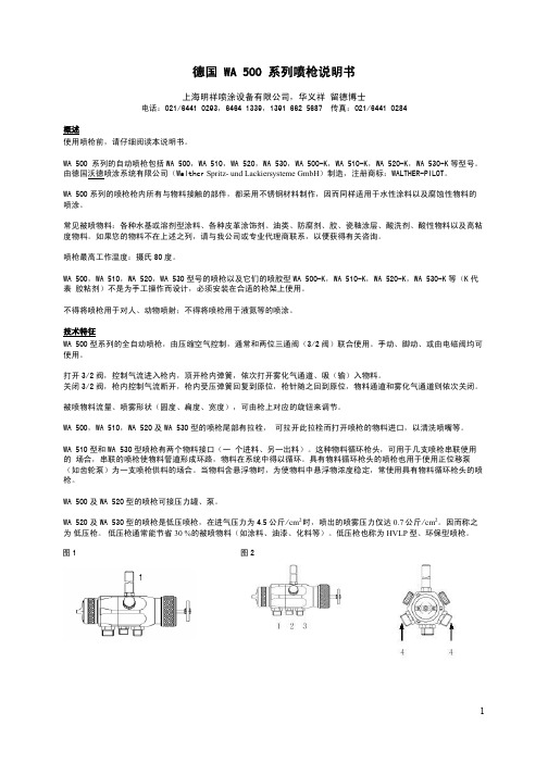
为了避免在喷嘴组件过程中发生损伤,请以下面的顺序更换喷嘴组件: 卸枪针->卸空气帽->卸喷嘴->装喷嘴->装空气帽->装枪针。
空气帽的更换: - 旋松固定空气帽的螺帽(零件图上 1 号件) - 取下空气帽(零件图上 2 号件) - 套上所需的空气帽 - 拧紧固定空气帽的螺帽(零件图上 1 号件)
4
8. 装上新的枪针密封组件 其余部件按相反程序安装。 注意:务必不要使用旧的枪针密封组件。
更换喷嘴、枪针、弹簧和密封件
以下部件的更换,请按“喷嘴、枪针的更换”一节描述的步骤进行:喷嘴、压簧(零件图上 32 号件)、枪针、针簧 (零件图上 35 号件)、活塞密封件(零件图上 29 号件)、O 型圈。其中,枪针、针簧、密封件、O 型圈需用非酸性的 润滑剂润滑。
启动/关闭喷枪时的要求 喷枪上的控制气、雾化气和物料压力正常。
物料压力不得超过: 10 公斤/cm2; 控制气流压力不得低于:4.0 公斤/cm2。
启动/关闭喷枪可由操纵 3/2 阀来进行。
使用完毕后,喷枪上的控制气压力、雾化气压力和物料压力都应卸掉,使喷枪不再受压。
喷雾形状的调节 在以下情况下应当调试喷雾图案,以获得理想的喷涂效果:首次使用喷枪、更换被喷物料、喷枪维修保养后。
WS550 450Mbps 无线路由器_用户指南_01_中文

WS550 450Mbps 无线路由器用户指南目录1产品简介 (5)功能简介 (5)接口和按钮 (6)指示灯 (7)2硬件安装 (9)选择合适的安装位置 (9)在小区宽带网络中连接WS550 (9)在DSL 宽带网络中连接WS550 (9)在有线电视宽带网络中安装WS550 (10)连接计算机或其他设备 (10)接通电源 (11)3配置上网参数 (12)设置计算机IP 地址 (12)首次安装配置 (15)登录Web 配置界面 (16)配置因特网连接 (17)配置计算机拨号连接 (18)4建立计算机的无线连接 (24)通过WPS 按钮建立无线连接 (24)通过手动方式建立无线连接 (24)5网络安全设置 (27)提高无线网络安全性 (27)修改无线网络名称和密码 (27)仅允许指定的计算机连接无线网络 (27)控制计算机上网权限 (28)过滤不适合访问的网站 (29)控制计算机使用的带宽流量 (30)设置防火墙等级以防止网络攻击 (31)防火墙等级说明 (31)配置防火墙 (31)6无线网络设置 (33)扩展无线网络覆盖范围 (33)开启智能覆盖功能 (36)7维护指南 (37)修改登录Web 配置界面的IP 地址 (37)备份配置 (37)恢复配置 (38)通过Web 配置界面恢复出厂设置 (38)通过复位按钮恢复出厂设置 (39)通过导入已备份数据恢复配置 (39)软件升级 (40)节能设置 (41)8华为路由伴侣 (42)9参考操作 (43)启用Windows 操作系统的无线配置服务 (43)查看计算机MAC地址 (43)10常见问题解答 (46)11附录 (47)技术规格 (47)出厂缺省设置 (47)12获取更多信息 (48)13法律声明 (49)1产品简介功能简介WS550 450Mbps 无线路由器(以下简称“WS550”)是一款专为家庭和小型办公用户精心打造的高速无线路由产品。
●超强以太网稳定性和可靠性,一键式零配置即可实现多台电脑同时上网,使您免于频繁掉线的烦恼。
WS5焊机说明书正文
电弧焊接是危险的作业,应尽力保护每个人,避免造成伤害和死亡。
应该让儿童远离焊机。
操作者在操作之前应该向医生咨询个人健康状况。
阅读并理解下面的安全说明。
为了更好的安全操作,建议仔细阅读国家关于焊接和切割的标准。
1.电磁场1.1 电流经过任何导体都可能产生电磁场。
焊接电流在焊接电缆与焊机周围都将产生电磁场。
1.2 电磁场可能对操作者的身体健康有影响,操作者在焊接以前必须咨询医生。
1.3 暴露在焊接电磁场中可能还会引起一些未知的健康方面的影响。
1.4 为了减小焊接电磁场的影响,所有操作者应当遵循下面的说明。
1.4.1 工件电缆与电极电缆应该捆在一起。
1.4.2 避免电极电缆或工件电缆环绕你的身体。
1.4.3 操作者不要处于电极电缆与工件电缆中间,如果电极电缆在你的右边,那么工件电缆也应该在你的右边。
1.4.4 焊接的时候,到工件的焊接电缆应尽可能的短。
1.4.5不要在靠近第二个焊接电源的地方进行焊接。
2.小心触电2.1 焊接时,电极与工件电路都会有电,禁止裸露的皮肤、潮湿的衣物接触它。
2.2 操作者必须穿戴良好的绝缘鞋、手套、衣物等,使自己与工件、地可靠地绝缘。
除了基本的安全警告以外,如果焊接必须在可能造成电力伤害的地方进行(如在潮湿的环境中、穿湿衣物、在导电金属上面、在狭窄的地方、有可能偶然接触工件或地),应使用下面的设备:2.2.1 半自动直流焊机2.2.2 有空载断电功能的直流焊机2.2.3 有空载断电功能的交流焊机2.3 在半自动或者自动焊接中,焊接电极、电极轴、导电嘴,喷嘴、半自动焊枪都有电,操作者应严防电击。
2.4 确保工件电缆与焊接金属接触良好,焊接电缆应尽可能的短。
2.5 确保焊接的工件有良好的接地线。
2.6 确保焊接电极,工件夹,焊接电缆和焊机工作良好。
更换损坏了的绝缘零部件、材料。
2.7 严禁要把焊接电极放进水中冷却。
2.8 不要同时连接两台焊机的电极,因为空载电压可能是两台焊机电压的总和。
WS_繁体中文使用说明书_V1.0
四種單位 N-m, ft-lb, in-lb, kg-cm,可供選擇
5 分鐘進入省電模式 可使用充電電池
1
各部件功能及名稱 30 N-m ~ 135 N-m 系列
操作設定值,然後再回到 0 N-m 。 *5: 環境測試包括:
a. 高溫試驗 b. 低溫試驗 c. 高溫高溼試驗 d.溫度變化試驗 e. 衝擊試驗 f. 振動試驗 g. 落下試驗 *6: 電磁相容性測試包括 : a. 靜電測試(ESD) b.輻射耐受 (RS) c. 輻射量測(RE)
6
使用扳手前注意事項
置入電池 打開電池蓋。 置入兩個 AAA 或是 AA 電池到電池盒中,請
注意正負極方向。 裝上電池蓋,並將電池蓋旋轉至定位。
電池蓋
電池
30 N-m ~ 135 N-m 系列
電池及電池蓋放入方向
200 N-m ~ 340 N-m 系列
注意: 當開啟 30Nm~135Nm 系列扳手的電池蓋時, 將會發現有一個觀測窗,此觀測窗可以觀測 試水貼紙的顏色,以判斷此扳手是否曾經遭 水入侵。
3~60
225
WS3-085 85
3/8 8.5~85 271
WS3-135 135 3/8 6.8~135 380
WS4-135 135 1/2 6.8~135 380
全部型號
精確度*1 操作模式
CN
順時針:±3% 反時針:±4%
峰值保持(P)/追隨(T)
單位選擇
N-m, in-lb, ft-lb,kg-cm
各部件功能及名稱 200 N-m ~ 340 N-m 系列
500 Series Diode Bridge Compressor 产品说明书
535500 Series Diode Bridge CompressorOperations Manual1. Read these instructions.2. Keep these instructions.3. Heed all warnings.4. Follow all instructions.5. Do not use this apparatus near water.6. Clean only with a dry cloth.7. Do not block any ventilation openings. Install in accordance with themanufacturer’s instructions.8. Do not install near any heat sources such as radiators, heat registers, stoves, or other apparatus (including amplifiers) that produce heat.9. Do not defeat the safety purpose of the polarized or grounding-typeplug. A polarized plug has two blades with one wider than the other.A grounding-type plug has two blades and a third grounding prong.The wide blade or the third prong are provided for your safety. If theprovided plug does not fit into your outlet, consult an electrician forreplacement of the obsolete outlet.10. Protect the power cord from being walked on or pinched particularly atplugs, convenience receptacles, and the point where they exit from theapparatus.11.12. Use only with a cart, stand, tripod, bracket, orthe apparatus. When a cart is used, use cautionavoid injury from tip-over.13. when unused for long periods of time.14. Refer all servicing to qualified service personnel. Servicing is requiredwhen the apparatus has been damaged in any way, such as power-supply cord or plug is damaged, liquid has been spilled or objects have fallen into the apparatus, the apparatus has been exposed to rain or moisture, does not operate normally, or has been dropped.15. This apparatus shall not be exposed to dripping or splashing, and noobject filled with liquids, such as vases or beer glasses, shall be placed on the apparatus.16. Do not overload wall outlets and extension cords as this can result in a risk of fire or electric shock.17. This apparatus has been designed with Class-I construction and mustbe connected to a mains socket outlet with a protective earthingconnection (the third grounding prong).18. This apparatus has been equipped with a rocker-style AC mains power switch. This switch is located on the rear panel and should remainreadily accessible to the user.19. The MAINS plug or an appliance coupler is used as the disconnect device, so the disconnect device shall remain readily operable.20. N OTE: This equipment has been tested and found to comply with the limits for a Class B digital device, pursuant to part 15 of the FCC Rules. These limits are designed to provide reasonable protection against harmful interference in a residential installation. This equipment generates, uses, and can radiate radio frequency energy and, if not installed and used in accordance with the instructions, may cause harmful interference to radio communications. However, there is no guarantee that interference will not occur in a particular installation. If this equipment does cause harmful interference to radio or televisionreception, which can be determined by turning the equipment o and on, the user is encouraged to try to correct the interference by one or more of the following measures:• Reorient or relocate the receiving antenna.• Increase the separation between the equipment and the receiver.• Connect the equipment into an outlet on a circuit different from that to which the receiver is connected.• Consult the dealer or an experienced radio/TV technician for help. CAUTION: Changes or modifications to this device not expressly approved by Rupert Neve Designs LLC, could void the user's authority to operate the equipment under FCC rules.21. This apparatus does not exceed the Class A/Class B (whichever is applicable) limits for radio noise emissions from digital apparatus as set out in the radio interference regulations of the Canadian Department of Communications.ATTENTION — Le présent appareil numérique n’émet pas de bruits radioélectriques dépassant las limites applicables aux appareils numériques de class A/de class B (selon le cas) prescrites dans le réglement sur le brouillage radioélectrique édicté par les ministere des communications du Canada.22. Exposure to extremely high noise levels may cause permanent hearing loss. Individuals vary considerably in susceptibility to noise-induced hearing loss, but nearly everyone will lose some hearing if exposed tosufficiently intense noise for a period of time. The U.S. Government’s Occupational Safety and Health Administration (OSHA) has specifiedthe permissible noise level exposures shown in the following chart. According to OSHA, any exposure in excess of these permissible limits could result in some hearing loss. To ensure against potentially dangerous exposure to high sound pressure levels, it is recommended that all persons exposed to equipment capable of producing highsound pressure levels use hearing protectors while the equipment is in operation. Ear plugs or protectors in the ear canals or over the ears must be worn when operating the equipment in order to preventpermanent hearing loss if exposure is in excess of the limits set forth here:Important Safety InstructionsWARNING — To reduce the risk of fire or electric shock, do notexpose this apparatus to rain or moisture.Duration, per day in hours Sound Level dBA, Slow Response Typical Example 890Duo in small club 692495Subway Train3972100 Typical music via head phones 1.51021105Siren at 10 m distance 0.51100.25 or less 115Loudest parts at a rock concert535 Diode Bridge CompressorThank you for your purchase of the 535 Diode Bridge Compressor. We hope you enjoy using this tool as much as we have enjoyed designing it. Please read through the entire manual before attempting to setup or operate your 535 Diode Bridge Compressor.535 Design NotesRupert Neve’s original 2254 compressor served as an inspiration for the design of the 535. Understanding that there were limitations to the original 2254 topology, painstaking effort was taken to reproduce the desirable qualities of the 2254 while improving the original device’s elevated noise floor, inflexible attack time constants, limited range of threshold and ratio controls, and low saturation headroom.The updated compressor design employs full-wave rectification in the sidechain to help minimize the effects of intermodulation distortion in the main audio path, while maintaining the tonality that made the original 2254 famous. Using a diode bridge as a gain control element in a compressor produces a unique sonic character, and it was imperative for the new compressor to deliver what the vintage device inspired.In addition to full-wave rectification in the compressor sidechain path, the TIMING controls have been expanded. Each of the six selectable settings have been chosen for different dynamic applications, including FAST and MF mode for more transient signals to SLOW and AUTO for more generalized applications. Combine this control set with the FAST switch, and the available TIMING control settings have been doubled from 6 to 12.Previous Rupert Neve Designs compressors like the 543 and Portico II series have been about transparency: the 535 is about punch, vibe, and color. The character of the Diode Bridge in combination with an upgraded feature set provide a versatile update to a vintage compressor topology for the modern studio engineer.535 FeaturesThresholdThe THRESHOLD control has 31 detents and allows the user to adjust the point at which compression begins, between -25dBu and +20dBu. Turning this control counter-clockwise will increase the amount of compression; turning it clockwise will decrease the amount of compression. If the input signal is lower than the set threshold, no compression will occur.It is advisable to start with this control set fully clockwise, and set the other controls first. Once the other controls are set to the desired values, slowly bring the THRESHOLD control down (turning counter-clockwise), while listening carefully until the optimal amount of compression is achieved for the givensource material.GR MeterEight segment LED meter that indicates gain reduction.Level MeterEight segment LED meter that indicates output level.Gain31 detent pot thatadjusts output gain from -6dB to +20dB.Comp InSwitch that inserts the compressor into the audio path.FastSwitch that divides the compressor attack and release times in half.LinkSwitch that allowsmultiple modules to be operated in stereo.S/C HPFSwitch that inserts a 150Hz high pass in the compressor sidechain.Blend31 detent pot that adjusts the mix of compressed and uncompressed signal.TimingSix posi�on rotary switch that sets the compressor a�ack andrelease �mes.Ra�oSix posi�on rotary switch that sets the slope of compressionfrom 1.5:1 to 8:1.Threshold31 detent pot that sets the level at which compression begins from -25dB to +20dB.The RATIO control has 6 selectable positions on the rotary switch and allows the user to set the slope of the compressor curve, with pre-selected ratios of 1.5:1 through 8:1. This range of compression ratios allows the user to compress very moderately, or if desired, dole out heavy compression to achieve an intentional effect on higher ratio settings.TimingThe TIMING control allows the user to change the attack and release times simultaneously for the diode bridge compressor. Each TIMING setting has a different attack and release time constant. Due to the nature of this topology, these time constants will adapt themselves slightly depending on several factors: compression ratio, threshold, and source material. This allows the diode bridge compressor to remain flexible with various types of source material. We encourage the user to experiment with different combinations of ratio, timing, and threshold settings to achieve the desired compression on the signal.FAST Fast Attack (750us), Fast Release (130ms)MF Medium Attack (2.25ms), Fast Release (130ms)MED Medium Attack (2.25ms), Medium Release (400ms)MS Medium Attack (4ms), Slow Release (725ms)SLOW Slow Attack (10ms), Slow Release (1S)AUTO Medium Attack (5ms), Dual Decay Release (T1 500ms, T2 1s) GainThe GAIN control has 31 detents and allows the user to add gain to the compressed signal in order to bring the signal level back up to unity with the uncompressed input signal. It is much easier to evaluate the tonal effect of the compressor when the compressed output level is matched to the uncompressed input level, thereby eliminating the misleading level difference.BlendThe BLEND control has 31 detents and allows the user to mix the uncompressed (dry) signal with compressed (wet) signal. Turning the control towards 0% will shift the mix to fully uncompressed dry signal, whereas turning the control towards 100% will shift the mix to the fully compressed signal. This feature allows for parallel compression by blending the direct and compressed signals, enabling a wider range of compression subtlety.The FAST switch divides the attack and release times available on the TIMING control in half, effectively doubling the number of TIMING presets available to the user.LinkThe LINK switch allows the compressor to be linked to another 535 compressor module via a sidechain control voltage. In link mode, the compressor generating the greater sidechain voltage (resulting in higher amounts of compression) will control the compression of both audio signal paths to maintain proper stereo image while compressing.Sidechain HPFThe S/C HPF switch allows the user to insert a 150Hz high-pass filter in the compressor sidechain. When this filter is engaged, the compressor will be considerably less responsive to information below 150Hz. As an example, if used on a drum kit, the low end of the kick drum would be less compressed than the snare drum or cymbals since a significant portion of the kick drum’s dynamic energy is focused below 150Hz.Comp InThe COMP IN switch allows the user to audition the compression. By disengaging the COMP IN switch, the compressor is bypassed and the user can quickly compare the sound of the dry input signal for an objective evaluation of the sonic effect of the compressor on the audio signal. COMP IN can be used in combination with the GAIN control to match the perceived level of the compressed audio signal with the level of the uncompressed input signal.Level and Gain Reduction MeteringThese two LED meters are provided to give an accurate representation of the output level of the compressor, as well as the amount of gain reduction being applied to the input signal.Operation GuideUnderstanding the signal paths involved in creating an accurate gain control device is an important step to using a compressor effectively. At the heart of the 535 is a Diode Bridge, manipulated by a control voltage which is generated by the compressor sidechain. The purpose of a compressor sidechain is to convert the input audio signal into the corresponding control voltage. Within the sidechain, several controls are available to the user including THRESHOLD, RATIO and TIMING. Using these controls, the user can manipulate the sidechain signal at key points to achieve proper control over the main audio path. The sidechain for this compressor receives audio input from a point immediately after the Diode Bridge, making it a feedback-style compressor.The 535 compressor sidechain has been upgraded with a Full-Wave rectifier rather than the Half-Wave detector of past Diode Bridge designs. This guarantees lower overall intermodulation distortion and faster available attack times in comparison to the original. This compressor was designed with the ability to “color” the audio passing through it; this can be achieved in the following ways: The first method is using higher input levels, which cause the Diode Bridge gain reduction element to produce its own harmonic content, regardless of whether the compressor is compressing the audio signal or not. This harmonic threshold has been set to +20dBu (to correspond with the maximum THRESHOLD control setting), allowing most signals to pass unaffected. However if desired, the user can drive the compressor input harder in order to bring out the more aggressive tonal characteristics. These harmonics are independent of frequency, and they increase exponentially beyond +20dBu. We encourage the user to experiment with varying input levels to find the right tonal shaping for the given source material.The second method is using higher RATIO and faster TIMING control settings. Faster TIMING settings will smooth the compressor control voltage less, and therefore induce more harmonic content, as peak to peak control voltage ripple will be greater. This will translate to more color in the main audio path. Slower TIMING settings will smooth the control voltage significantly, and thereby reduce the harmonic content added to the audio path, resulting in more transparent compression. The harmonic content created in this way is what contributes to the Diode Bridge Compressor’s renowned warm character.R a ti o C u r v e sI n p u tO u t p u tL e g e n dR A T I O S e tti n g s 1:1 (B Y P A S S ) 1.5:12:13:14:16:18:1T h e r a ti o c u r v e s s h o w n a b o v e w e r e t a k e n w i t h T H R E S H O L D s e t t o t h e f o l l o w i n g v a l u e s :-25d B u -10d B u 0d B u +10d B uOperation Guide ContinuedHaving covered some of the ways in which this compressor can be used to color the audio signal, it is important to note that this compressor can also be utilized in more transparent applications. There are several methods that can be used individually or in combination for increased compression subtlety:- Lower RATIO control settings (1.5:1, 2:1, 3:1)- Slower TIMING control settings (MS, SLOW, AUTO)- Engaging S/C HPF to remove low frequency compression- Utilizing the BLEND control to mix the uncompressed signal with compressed signal (parallel compression)The range of attack and release times that can be achieved across the various RATIO settings is quite wide, and is useful for dialing in the proper compression envelope. Due to the nature of the charge and discharge characteristics of the timing networks in this compressor, there is an inherent flexibility in the timing range for each of the six switch positions on the TIMING control.Limited WarrantyRupert Neve Designs warrants this product to be free from defects in materials and workmanship for a period of one (1) year from date of purchase, and agrees to remedy any defect identified within that period by, at our option, repairing or replacing the product.Limitations and ExclusionsThis warranty, and any other express or implied warranty, does not apply to any product which has been improperly installed, subjected to usage for which the product was not designed, misused or abused, damaged during shipping, damaged by any dry cell batter, or which has been altered or modified in any way. This warranty is extended to the original end user purchaser only. A purchase receipt or other satisfactory proof of original purchase is required before any warranty service will be performed. THIS EXPRESS, LIMITED WARRANTY IS IN LIEU OF ALL OTHER WARRANTIES, EXPRESS OR IMPLIED, TO THE EXTENT ALLOWED UNDER APPLICABLE STATE LAW. IN NO EVENT SHALL RUPERT NEVE DESIGNS BE LIABLE FOR ANY SPECIAL, INCIDENTAL, OR CONSEQUENTIAL DAMAGES RESULTING FROM THE USE OF THIS PRODUCT. Some states do not allow the exclusion or limitation of consequential damages or limitations on how long an implied warranty lasts, so this exclusion may not apply to you.Warranty ServiceI f you suspect a defect in your device, please call us at 512-847-3013 or contact our support staff (**********************)for troubleshooting. If it is determined that the device is malfunctioning, we will issue a Return Material Authorization and provide instructions for shipping the device to our service department.Rupert Neve DesignsPO Box 1969Wimberley TX 78676tel: +1 512-847-3013fax: +1 512-847-8869PN: 775-00028 revB。
WS-系列说明书
欢迎您使用“焊王”焊机产品!在使用本机之前,请仔细阅读本说明书,并妥善保存,以备查询。
警告:本机内有危险电压,非专业人员请勿打开机盖!本公司是集焊接切割设备开发设计、生产制造、销售及售后技术服务为一体的专业公司,已通过德国TUVISO9001质量体系认证,认证号码为:781005111。
我公司始终贯彻“追求卓越,品质第一”的企业宗旨,在本行业中位居前列,销售及售后服务网络已遍及全国。
本公司拥有下述几大类产品系列,年生产销售万台焊接切割设备。
各系列产品均通过 “CQC ”认证。
获得 “3C ”认证证书。
本系列可控硅直流氩弧焊机的3C 证书编号为:2003010604083864 本公司生产的“焊王”牌产品现有系列: *直流氩弧焊机系列 *交直流氩弧焊机系列 *气保护焊机系列 *直流手工焊机系列*空气等离子切割机系列 *数控电阻焊机系列 *储能螺柱焊机系列 *埋弧焊机系列*焊接自动化专机系列 *焊接辅助专用设备系列本公司将继续沿着产品专业化、通用化、系列化方向发展,使产品的使用性能及可靠性接近或达到国际先进水平。
公司简介~~~~~~~~~~~~~~~~~~~~~~~~~~~~在焊机安装\使用前,请认真阅读使用说明书。
安全警告!在使用焊机过程中,可能会给您和他人造成伤害,因此在焊接时作好防护。
详细情况请参考符合生产商事故预防要求的操作人员安全防护指南.! !.按照应用标准,安装好接地装置。
.在皮肤祼露、戴有湿手套或穿着湿衣服时,禁止接触带电部件或电焊条。
.确保您和地面及工作间是绝缘状态。
.确认您的工位是安全状态。
烟气———可能会有害健康!.让头部保持在烟气之外。
.在弧焊时,使用通风或抽气装置,避免吸入烟气。
弧光辐射———可能会损坏您的眼睛,灼伤皮肤!.使用合适的焊接面罩和滤光镜,穿上防护服,以保护您的眼睛和身体。
.用合适的面罩或帘保护旁观者以免受到伤害。
火灾.焊接火花可能会导致失火,请确认焊接工位附近无易燃物。
- 1、下载文档前请自行甄别文档内容的完整性,平台不提供额外的编辑、内容补充、找答案等附加服务。
- 2、"仅部分预览"的文档,不可在线预览部分如存在完整性等问题,可反馈申请退款(可完整预览的文档不适用该条件!)。
- 3、如文档侵犯您的权益,请联系客服反馈,我们会尽快为您处理(人工客服工作时间:9:00-18:30)。
使用超声波传感器技术测量风速风
气压 风向 风速
测量的结果也支持以下协议: - UMB-Binary - UMB-ASCII - SDI-12 - MODBUS
配件
防护等级
IP66
规格
直径 150 mm 高度 287 mm
重量
1.2Kg
接口
RS485, 双线连接方式,半双工
精度
±2 % RH
原理
MEMS 电容式
测量范围
300…1200 hPa
精度
±0.5 hPa (0 … +40°C)
原理
超声波
测量范围
0 – 359.9°
精度
均方根误差< 3 °(>1.0 m/s)
原理
超声波
测量范围
0…75 m/s
单位
m/s; km/h; mph; kts
精度
测量值±0.3 m/s 或最大值的 3% (0~35 m/s) 5% (>35m/s)
电源
24VDC ±10% (无加热时)
工作温度
-50…75 °C
工作湿度
0…100% RH
加热功率
20VA @ 24VDC
原理
NTC 负温度系数热敏电阻
测量范围
-50…60 °C) 其他 ±0.5 °C (>-30 °C)
原理
电容式
测量范围
0…100 % RH
WS500-UMB——温度,气压,相对湿度,风
来自 WS 产品系列的专业智能测量 传感器,带有可应用于环境测量 的数字接口。
WS500-UMB 集成多功能气象仪可以测 量:
- 气压 - 相对湿度 - 风向 - 风速 - 温度
WS500-UMB WS500-UMB
技术参数
温度 相对湿度
相对湿度的测量是通过电容传感元 件。
AB20
超声波传感器 应用于温度/湿度测量 开放式的通信协议: - UMB-ASCII - UMB-Binary - SDI-12 - MODBUS - 与 8160.UDAC 连接后是模拟量输出
由于本公司产品在不断更新,如说明上的内容不符,本公司不负责通知
浪涌防护器
电源 24V/4A
UMB 接口转换器 ISOCON
数模转换器 DACON8-UMB
温度传感器 WT1
路面温度传感器 WST1
雨量传感器 WTB100
连接线 20m
订货号 8373.U01
P V1 8160.UISO 8160.UDAC 8160.WT1 8160.WST1 8353.10