ST LINK V 使用说明
STLINK和JLINK使用 SWD四线 调试 下载STM32

For my breadboarded test rig, I used a four pin Harwin M20 connector. Even on a half size micromouse, this will not take up much room and I may use it as the only debug/programming connector.The pins on the 20-pin standard JTAG connector to use are:Pin 1 – VCC:This is the traget board Vcc. It is used by the STLINK/V2Pin 7 – TMS/SWDIO:The SWD Data signalPin 8 – GND:Be sure there is a common groundPin 9 – TCK/SWCLKThe SWD Clock SignalPin 15 – nSRST/RESETSystem reset – probably optional(你可以不要这个复位pin,直接关电源再上电来复位)ST-Link/V2 JTAG/SWD接口定义:可以自己做一些转接PCB板子,现在USB四线的可以用起来。
做一个现在智能手机usb接口,接四根线就好SWD不单单可以下载还可以单步调试,速度比JTAG快。
有人问,那为什么要发明JTAG这个20pin 的接口呢?因为JTAG标准制定不是为了下载程序调试程序用的,它用来做“边界扫描”用的,什么是边界扫描不知道的可以搜搜一些,在国内谷歌需要翻墙软件才好用。
百度搜索专业术语类不好用,最近我发现好多东西搜搜比百度好用不少。
海康视频管理软件用户手册

约定
在本手册中为了简化描述,做以下约定: 网络视频监控软件iVMS-4200简称为软件。 网络硬盘录像机、混合型网络硬盘录像机、视频服务器、NVR、IP Camera和IP Dome等统一称为设备。 点击为鼠标左键单击;双击为鼠标左键双击;右键单击为鼠标右键单击。 部分图片为示意图,请以软件实际界面为准。
iVMS-4200 客户端
用户手册 V2.0
UD.6L0102C0310A01
1
iVMS-4200 用户手册
前言
前言
非常感谢您购买我公司的产品,如果您有什么疑问或需要请随时联系我们。
适用型号
本手册适用于网络视频监控软件iVMS-4200。
声明
本手册可能包含技术上不准确的地方、或与产品功能及操作不相符的地方、或印刷错误。我司将根据产品功能的增 强或变化而更新本手册的内容,并将定期改进及更新本手册中描述的软硬件产品。更新的内容将会在本手册的新版 本中加入,恕不另行通知。 本手册中内容仅为用户提供参考指导作用,不保证与实物完全一致,请以实物为准。
符号约定
在本文中可能出现下列标志,它们所代表的含义如下。 符号 注意 说明 表示有潜在风险,如果忽视这些文本,可,是对正文的强调和补充。
0200001030509
i
iVMS-4200 用户手册
目录
目
目
录
前言 ..................................................................................................................................................................................
ST LINK V2使用手册1.3--先看这个文档
1, ST-LINK V2 ST 官方相关软件资料下载地址:
/web/en/catalog/tools/FM146/CL1984/SC720/SS1450/PF251168?s_searchtype=partnumber#
STM8 & STM32用户:
耐压 3.3V 以上的
2 , stlink v2 仿真 stm8 ,stlink v2 不会对目标供电,目标板需要另外供电;
3, 接线说明(for stm8)按照 ST LINK v2 背面 标签说明接线,这里需要强调的是 VCC 脚 需要外部供电(5v--3.3v), 不会输出电压,所以测试电压为 0v;
二 项 )) 3, 其 他 设 备 STM32 STLink 右 单 击 菜 单 更 新 设 备 驱 动 4, 选 择 自 动 搜 索 更 新 的驱 动 程 序 软 件( S) 5, 在 弹 出 的 Windows 无 法 验 证 此 驱 动 程 序 软 件 的 发 布 者 对 话 框 选 择 : 始 终 安 装 此 驱 动 程 序软件 ( I)
(4) Settings 设置对话框,接口设置成 JTAG ,JTAG Device Chain 是检查到 STM32 JTAG id 号; (4) Settings 设置对话框,接口设置成 SW ,SW Device 是检查到 STM32 SW id 号;
(5)切换到 Utilities 标签 , 选择 ST-Link Debugger ,选择 Updata Target before Debugging (flash 调试), 点击 Settings,添加 STM32型号
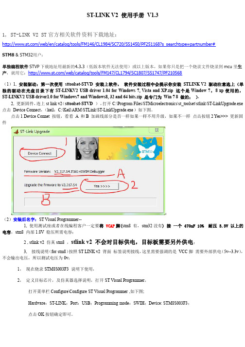
点击 1 Device Connet 按钮,看看 A 和 B 加画线部分是否一样如果一样不用升级,如果不一样 点击按钮 2 Yes>>> 更新固 件
ST-LINK-V2详细教程分享
3.GND 三根必需
3.驱动安装与固件升级
3.1 驱动的安装
从光盘或者网上找到 st-link_v2_usbdriver.exe 文件,与普通软件一样双击安装,保持 默认路径。安装完成后将 STLINKV2 插入电脑的 USB 接口,此时计算机会提示发 现新硬件,并提示安装驱动,请选择自动安装。如果是 XP 系统,当弹出如下的提示时:
使用 STM32 ST-LINKUtility 可以给 STM32 芯片烧写程序。使用的方法如下: 将 ST-LINKV2 和 STM32 目标板使用 SWD 接口连接,将 ST-LINKV2 和 计算机相连。 打开 STM32 ST-LINK Utilit 软件。在菜单栏中找到菜单项“Target”,点击子菜单 “connect”,在软件下方的状态栏会输出以下信息:
这样就成功下载了程序到我们的板子。
7.2 STVP对STM8 OPTION配置
STM8SMCU具有配置字 option,可以让开发者对芯片 GPIO 第二功能,内部看门 狗,时钟特性等进行配置,还可以令开发者对芯片程序进行上锁。
当需要使用时,通常我们运用 STVP软件对 MCU 配置字进行设置(通过 ST-LINK SWIM接口进行烧录)。打开 STVP软件,选择 MCU类型,点击下方 option选项卡, 我们将看到下图的各种配置字信息:
1.初识ST-LINK V2
ST-LINK/V2 是STM8 和STM32 微控制器系列的在线调试器和编程器。 单线接口模块(SWIM)和串行线调试(SWD)接口用于与应用板上的 STM8 和 STM32 微控制器通讯。 STM8 的应用使用 USB 全速接口与 ST Visual Develop (STVD), ST Visual Program(STVP)或 IAREWSTM8 等集成开发环境通讯。 STM32 的应用使用 USB 全速接口与 Atollic, IAR,Keil 或 TASKING 等集成开发环 境 通讯。 功能简介: ■ 通过 USB 接口供电; ■ USB2.0 全速兼容接口; ■ SWIM 和 SWD 独立接口: SWD---SWDIO、SWCLK,适用于 STM32 全系列芯片开发 SWIM—RST、SWIM,适用于 STM8 全系列芯片开发 ■ 支持固件在线升级; ■ 电源 LED 指示和调试信号 LED 指示.
凌跃智能奋斗者开发板 使用说明书
凌智奋斗者学习开发板使用说明书******时间:2022年8月31日版本:V0.02目录一、目的 (3)二、硬件介绍 (3)三、资料包 (6)四、开发工具 (7)1、硬件开发工具 (7)2、软件开发工具 (11)五、实验操作 (12)1、软件安装 (12)2、硬件连接 (12)3、工程开发 (16)六、例程介绍 (23)七、产品介绍 (27)一、目的本说明书是针对凌智奋斗者学习开发板硬件而编写的,此手册针对GD32F103芯片开发进行说明,主要包括硬件介绍、核心电路说明,开发环境配置,程序使用等内容,从硬件、软件、开发等方面展开介绍。
二、硬件介绍1、核心板【1】主控芯片:GD32F103ZET6芯片;【2】EEPROM:M24C08;【3】提供8MHZ晶振,实现HSE实验;【4】提供32.768KHZ晶振,实现LSE实验;【5】外置FLASH:W25Q64芯片;【6】SRAM:IS62WV51216BLL芯片;【7】NANDFLASH:GD9FU1G8F2AMGI【8】复位按键:核心板板载复位按键;【9】板载AMS1117 3.3电源芯片,稳定输出3.3V;【10】MicroUSB:可以单独为核心板供电;【11】板载电源指示灯,观察核心板供电。
2、控制底板【1】提供9-24V电源输入接口,板载稳压芯片:TPS5430;【2】板载AMS1117 3.3电源芯片,稳定输出3.3V;【3】四路LED,方便观察程序运行,及学习IO操作;【4】四路独立按键,方便基于开发板进行项目开发;【5】一路独立唤醒按键,实现唤醒等实验;【6】一路复位按键,实现开发板复位;【7】标准JTAG接口(20针),支持SWD硬件仿真调试;【8】板载串口芯片CH340C,实现串口通信;【9】板载CAN总线芯片TJA1050,实现CAN总线通信;【10】板载485芯片SP3485,实现485串口通信;【11】开发板预留NRF2401接口,实现2.4G通信;【12】开发板预留ESP8266接口,实现Wifi通信;【13】板载蜂鸣器,方便观察程序运行;【14】板载10k可调电阻,实现ADC采样实验;【15】预留OLED接口,可以安装0.96寸液晶显示数据;【16】所有IO接口均引出,方便开发;【17】串口、485、CAN、EEPROM、Wifi均采用跳线的方式,减少对主控芯片的影响;【18】开发板预留多路3.3V和5V电源接口,方便连接外设进行项目开发;【19】预留BOOT0和BOOT1选择接口,根据实际开发项目进行选择使用;【20】板载开关及两路电源指示灯,方便观察和控制开发板状态;【21】开发板预留2.8寸LCD触摸液晶屏,兼容正点原子;【22】板载SD卡槽,可以利用SD卡存储数据;【23】板载继电器控制电路及继电器,预留常开与常闭接口,方便控制外设。
ST-LINK-V2在线调试器编程器说明-V2

ST-LINK/V2STM8和STM32在线调试器/编程器说明王志杰2014-6-8ST-LINK/V2是ST(意法半导体)公司的在线调试器/编程器,可调试和开发STM8全系列和STM32全系列的开发工具1 介绍目录1 介绍 (3)2 ST-LINK/V2支持软件 (5)3 STM32 ST-Link Utility (6)4 ST-LINK驱动程序 (6)5 ST-LINK接口 (8)6 ST-LINK固件升级软件 (8)7 ST-LINK/V2故障诊断步骤 (9)8 开源QSTLINK2 (10)9 批量生产工具 (11)- 2 - ST-LINK/V21 介绍ST-LINK/V2 王志杰/ QQ 411238869 - 3 -1 介绍目前,ST 提供了2种开发工具ST-LINK 。
ST-LINK/V2是STM8和STM32微控制器系列的在线调试器和编程器。
单线接口模块(SWIM )和JTAG/单线调试(SWD )接口用于与应用板上的STM8和STM32进行通讯。
开发STM8应用,可以配合ST Visual Develop (STVD)或ST Visual Program (STVP)使用。
开发STM32应用,可以配合Atollic 、IAR 、Keil 或TASKING 等集成开发环境使用。
ST-LINK/V2的ST 官方参考页:/internet/evalboard/product/251168.jsp图 1 ST-LINK/V21 介绍主要特点:●USB接口提供5V电源●USB2.0全速兼容接口●USB standard A到mini B线●SWIM特殊特点:-SWIM接口支持1.65 V到5.5 V的应用电压-SWIM支持低速和高速模式-SWIM编程速率:在低速模式,9.7Kbytes/s;在高速模式,12.8Kbytes/s●JTAG特殊特征:-JTAG接口支持1.65 V到3.6 V的应用电压,并能承受5V的输入-JTAG线连接一个标准的JTAG连接器,间距2.54mm,20PIN-支持JTAG通讯-支持串行线调试(SWD)和串行线查看(SWV)通讯●支持直接固件升级(UFU)●PC通讯状态的LED指示灯●温度范围0 到50 °C- 4 - ST-LINK/V22 ST-LINK/V2支持软件2ST-LINK/V2支持软件ST-LINK/V2支持工具:* 注:建议下载最新的软件版本ST-LINK/V2 王志杰/ QQ 411238869 - 5 -3 STM32 ST-Link Utility3STM32 ST-Link UtilitySTM32 ST-LINK工具软件兼容ST-LINK和ST-LINK/V2STM32 ST-LINK utility/st-web-ui/static/active/en/st_prod_software_internet/resource/tec hnical/software/utility/stsw-link004.zipUM0892 - STM32 ST-Link manual/st-web-ui/static/active/en/resource/technical/document/user_ma nual/CD00262073.pdfUM0892 - User manual - STM32 ST-LINK Utility software description /st-web-ui/static/active/en/resource/technical/document/user_ma nual/CD00262073.pdf4ST-LINK驱动程序ST-LINK/V2支持Vista,Vista64,WIN7,WIN7 64bit等系统。
深圳链威信息技术有限公司C4050-Q4手持终端用户手册说明书
SHENZHEN CHAINWAY INFORMATION TECHNOLOGY CO., LTD C4050-Q4 HandheldTerminalUser Manual1ContentsStatement (4)1.Getting Started (5)1.1Brief Instruction (5)1.2Precaution before Using Battery (6)2.About The Device (8)2.1Structure (8)2.2SD Card Installation (10)2.3SIM Card Installation (11)2.4Battery Installation (12)2.5Battery Charging (13)2.5.1Direct Charging (13)2.5.2Cradle Charging (13)2.6Device Power on/off (13)3.Call Function (14)3.1Phone (14)3.2Contacts (15)3.3Messaging (16)4.Barcode Reader (17)4.11D Barcode (17)4.22D Barcode (18)4.32D(S) Barcode (19)5. RFID Reader (20)5.1 Low Frequency (20)5.2 High Frequency (22)5.2.1 14443A (22)5.2.2 15693 (23)5.3 Ultra High Frequency (24)6.Fingerprint Reader (26)27.Other Functions (27)7.1PING (27)7.2Bluetooth (28)7.3GPS (30)7.4Volume Settings (31)7.5Sensor (32)7.6Keyboard (33)7.7Network (34)7.8Keyboardemulator (35)8.Device Specification (37)3Statement2017 by Shenzhen Chainway Information Technology Co., Limited. All rights reserved.No part of this publication may be reproduced or used in any form, or by any electrical or mechanical means, without permission written from Shenzhen Chainway. This includes electronic or mechanical means, such as photocopying, recording, or information storage and retrieval systems. The material in this manual is subject to change without notice.The software is provided strictly on an “as is” basis. All software, including firmware, furnished to the user is on a licensed basis. Shenzhen Chainway grants to the user a non-transferable and non-exclusive license to use each software or firmware program delivered hereunder (licensed program). Except as noted below, such license may not be assigned, sublicensed, or otherwise transferred by the user without prior written consent of Shenzhen Chainway. No right to copy a licensed program in whole or in part is granted, except as permitted under copyright law. The user shall not modify, merge, or incorporate any form or portion of a licensed program with other program material, create a derivative work from a licensed program, or use a licensed program in a network without written permission from Shenzhen Chainway.Shenzhen Chainway reserves the right to make changes to any software or product to improve reliability, function, or design.Shenzhen Chainway does not assume any product liability arising out of, or in connection with, the application or use of any product, circuit, or application described herein.No license is granted, either expressly or by implication, estoppel, or otherwise under any Shenzhen Chainway intellectual property rights. An implied license only exists for equipment, circuits, and subsystems contained in Shenzhen Chainway products.Shenzhen Chainway Information Technology Co., LtdAddress: 9/F, Building 2, Phase 2, Gaoxinqi Industrial Park, Liuxian 1st Rd, District 67, Bao’an, Shenzhen, Guangdong, ChinaTelephone:+0086-755-23223300 Fax: +0086-755-23223310Web Site:Email:*******************Web Site: 41. G etting Started1.1 Brief InstructionChainway C4050-Q4 is a series of Android powered smart terminals, with data capture, data processing, wireless communication. It is with high-reliability &high-expansibility. Auto & Accurate data collection is achieved in various business fields via a complete solution of premium options, the flexible solution among options and operators is suited-up. You will find out with C4050-Q4, much easier deployment, reduced complexity, decreased maintenance, are the benefits for enterprises.C4050-Q4 meets industrial level IP64 (IEC sealing), is sufficient to routine applications, eg, railway inspection, road parking toll, vehicle inspection, logistics express, power inspection, warehousing management, chain retail, etc. Whether the mobile operators are working indoor or outdoor, with Chainway C4050-Q4, your business is always &highly efficient on-line.Meeting industrial standards, designed to support various mobile solutions. With the build-in high performance Qualcomm 1.3GHz quad core processor technology, the operators need only one device to enjoy a convenient and easy job, C4050-Q4 will be the ideal choice for key-fact business in mobile solutions, for simplified task flow, enhanced work efficiency, for shortened time to customer response, more satisfied customer care service.Chainway C4050-Q4 comes with world wide band 4G LTE technology. Multi channels data and voice communication guarantees the real-time communication and data efficiency, C4050-Q4 brings you the best ROI.51.2 Precaution before Using Battery•Do not leave batteries unused for extended periods of time, either in the product or in storage. When the battery has not been used for 6 months, check the charge status and charge or dispose of the battery asappropriate.•The typical estimated life of a Lithium-Ion battery is about two to three years or 300 to 500 charge cycles, whichever occurs first. One chargecycle is a period of use from fully charged, to fully discharged, and fully recharged again. Use a two to three year life expectancy for batteries that do not run through complete charge cycles.•Please do use original battery to replace, wrong battery may cause fire, explosion. Please do keep the battery as recommended. •Rechargeable Lithium-Ion batteries have a limited life and will gradually lose their capacity to hold a charge. This loss of capacity (aging) isirreversible. As the battery loses capacity, the length of time it will power the product (run time) decreases.•Lithium-Ion batteries continue to slowly discharge (self-discharge) when not in use or while in storage. Routinely check the battery’s charge status.The user manual typically includes information on how to check battery status, as well as battery charging instructions.•Observe and note the run time that a new fully-charged battery provides for powering your product. Use the new battery run time as a basis tocompare run times for older batteries. The run time of your battery willvary depending on the product’s configuration and the applications that you run.•Routinely check the battery’s charge status.•Carefully monitor batteries that are approaching the end of their estimated life.6Consider replacing the battery with a new one if you note either of the following conditions:•The battery run time drops below about 80% of the original run time.•The battery charge time increases significantly.•If a battery is stored or otherwise unused for an extended period, be sure to follow the storage instructions in this document. If you do not follow the instructions, and the battery has no charge remaining when you check it,consider it to be damaged. Do not attempt to recharge it or to use it.Replace it with a new battery.•Always follow the charging instructions provided with your product. Refer to your product’s user manual and/or online help for detailed informationabout charging its battery.•Charge or discharge the battery to approximately 50% of capacity before storage.•Charge the battery to approximately 50% of capacity at least once every six months.•Remove the battery and store it separately from the product.•Store the battery at temperatures between 5 °C and 20 °C (41 °F and68 °F).782. A bout The Device2.1 Structure<Front>9<Back>Buttons: ButtonFunction Power ButtonPress and hold to turn the device on or off App List View Button View a list of apps running Home ButtonPress to return to the home screen Cancel ButtonTap to return to the previous screen2.2 SD Card InstallationDetailed installation steps are as follows:1. Open the SIM slot as the direction of ‘Open/Lock’ labeled.2. Open the SD slot as the direction of ‘Open/Lock’ labeled.3. Install the SD card properly.4. Lock the SD slot and SIM slot properly.102.3 SIM Card Installation1. Open the SIM slot as the direction of ‘Open/Lock’ labeled.2. Install the SIM card correctly.3. Lock the SIM slot properly.112.4 Battery Installation1. Push the battery down into the bottom of the battery.2. Push the battery to the direction of the array.3. Turn the battery lock.122.5 Battery Charging2.5.1 D irect ChargingUse the adapter to charge the battery via the USB connector of the snap-on.2.5.2 C radle ChargingConnect the adapter with the power cable to charge the device.2.6 Device Power on/offPress the ‘Power’ button on the side shortly due to turn on/off.13143. C all Function3.1 Phone1. Click this icon :2. Click the number button to input the numbers;3. Click the button to confirm and dial;4. Click theto end the calling;Contact s LogsVoice CallingEmulated Numeric Keypad153.2 Contacts1. Click ‘Contacts’ to open the contacts list.2. Click ‘’ to add the new contact.3. Click ‘’ to import/export or delete the contact list.GroupFavorites Contact List163.3 Messaging1. Click ‘’ to open the message list.2. Click ‘’ to input the content.3. Click ‘’ to send the message.4. Click ‘’ to add photos, videos.174. B arcode Reader4.1 1D Barcode1. Open the 1D Barcode Demo in Appcenter.2. Press the ‘Scan’ button to start scanning, then the auto interval parameters can also be set.184.2 2D Barcode1. Open the 2D Barcode Demo in Appcenter.2. Press the ‘Scan’ button to start scanning, then the auto interval parameters can also be set.4.3 2D(S) Barcode1. Open the 2D(S) Barcode Demo in Appcenter.2. Press the ‘Scan’ button to start scanning, then the auto intervalparameters can also be set.3. Also, the barcode types enabling/disabling can also be set.Note: Please scan the barcode in a correct way, otherwise the scanning might be failed.19205. RFID Reader5.1 Low Frequency1. Open the RFID_LF Demo within Appcenter and then press the ‘Scan’ button to start reading.2. Tag types including ID Card/Animal Tag/Hitag/HDX Tag/EM4450 can be also selected, and Hitag-S and EM4305 reading/writing are already supported by the device.Please ensure that the LF module is embedded in the device, also please select the tag type correctly, otherwise the operation might not work. Meanwhile, please pay attention to the HDX and FDX-B since they are using different hardware due to the different working principles.21225.2 High Frequency5.2.1 14443A1. Open the 14443A demo within Appcenter, and press the ‘Scan’ button tostart reading.2. Mifare and UltraLight reading/writing are also supported.5.2.2 156931. Open the RFID_15693 demo within Appcenter, and press the ‘Scan’button to start scanning.2. 15693 writing are also supported.23245.3 Ultra High Frequency1. Open the UHF demo within Appcenter, and press the ‘Start’ button to start scanning.2. Multiple tags reading and single tag reading/writing are also supported.25266. F ingerprint Reader1. Open the Fingerprint Demo in Appcenter.2. Put the finger to the fingerprint module and set the ID/name of the template under ‘ACQUISITION’.3. Put the finger to the fingerprint module properly and identify by ID/Name/Score under ‘IDENTIFICATION’.4. The local templates can also be checked under ‘Data’.Note: Please be aware that ISO standards are only supported by the ISO fingerprint hardware module.7. O ther Functions7.1 PING1. Open the Ping in Appcenter.2. Set the Ping parameters and select the internal/external addresses.27287.2 Bluetooth1. Open the Bluetooth demo in Appcenter and turn on the Bluetooth.2. Input the content or select the file, then scan the nearby Bluetooth printerand pair them.3. Select the printer and click ‘Print’ to print the content.29307.3 GPS1. Open the GPS demo in Appcenter and turn on GPS module.2. Set the GPS parameters and get the GPS data information.317.4 Volume Settings1. Open the Volume Setting demo in Appcenter.2. Set the volumes based on the requirements.327.5 Sensor1. Open the Sensor demo in Appcenter.2. Test the sensor based on the requirements.7.6 Keyboard1. Open the Keyboard demo in Handset Appcenter.2. Set and test the key values of the device.337.7 Network1. Open the Network demo in Appcenter.2. Test the WIFI/Mobile signal based on the requirements.34357.8 KeyboardemulatorKeyboard Emulator can be used directly for multiple using environments and the output formats can including prefix/suffix/enter/tap can also be defined, please define the options properly based on the features of the device.1. Open the KeyboardEmulator which is preinstalled in the device.2. Click the options correctly based on the features of the device hardware, please also press the physical button to define the scan button, then please define the output formats based on the requirements, finally click ‘Open’ to save and enable it.368. D evice SpecificationPhysical CharacteristicsDimensions 176mm x 76mm x 29mm/ 6.93 x 2.99 x 1.14inWeight 319g/ 11.25ozScreen 4’’ WVGA (480*800), 16.7M colorsKeyboard Numeric / QwertyBattery Main bat. (rechargeable li-ion polymer, 3.7V, 3200 mAh)Pistol bat. (rechargeable li-ion polymer, 3.7V, 5200 mAh)Expansion Slot MicroSD/TF, maximum capacity of 32GSIM Slot 1 PSAM, 1 SIM, 1 MicroSDAudio 0.5WCamera 8MP autofocus camera with flashPerformance CharacteristicsCPU Qualcomm 1.3GHz quad coreOS Android 5.1Memory 2GB RAM, Build-in 16GB FlashInterface USB Micro-B, serial port RS-232(TTL)Storage Card Type MicroSD cardMaximum Expansion Storage 32GBUser Environmental CharacteristicsOperating Temperature -10℃ to 50℃Storage Temperature -40℃ to 70℃Humidity 5%RH-95%RH(non-condensing)Dropping Survive 1.2m/3.9ft. drop, 6 sides (concrete floor under operating temp.)Sealing IP64, IEC complianceWireless Communication37WAN EU:2G: GPRS(900/1800MHz)3G: WCDMA B1 B84G: FDD-LTE:B1 B3 B7 B8 B20US:2G: GPRS(850/1900MHz)3G: WCDMA B1 B2 B54G: FDD-LTE: B2 B4 B7 B17CN:2G: GPRS(850/900/1800MHz)3G: WCDMA: B1 CDMA EVDD: EVDD Rev.A800MHz TD-SCDMA:B34 B394G: TDD-LTE: B38 B39 B40 B41 FDD-LTE: B1 B3WLAN IEEE802.11a/b/g/n, internal antennaWPAN Bluetooth v4.0 Low EnergyBluetooth 3.0+HSData CollectionBarcode Scan Engine 1D barcode(Symbol SE965, laser)(optional);2D CMOS laser scanner: Symbol SE4500(optional)Sensor resolution: 750 (horizontal ) * 480 (perpendicular) pixel (grayRFID LF 125KHz/134.2KHz, HDX/FDX-B(optional)HF 13.56MHz, ISO14443A/ISO15693(optional)UHF 860-960MHz, EPC C1 GEN2/ISO18000-6C(optional) NFC 13.56MHz,ISO/IEC 18092、ISO/IEC 21481 Developing EnvironmentSDK Chainway SDKProgramming Language JavaDeveloping Tool Eclipse/Android Studio38。
关于STLINK使用特别注意事项

ST-Link III通过高速USB2.0与PC端连接。
支持的软件
直接支持ST官方IDE(集成开发环境软件)ST Visual Develop(STVD)和烧录软件ST Visual Program(STVP)。
支持ATOLLIC,IAR和Keil公司的STM32的集成开发环境。
关于STLINK使用特别注意事项:
过去有客户反应STLINK有损坏的情况,经过对客户的回访以及与我们工程师在使用过程中的比对看来,出现STLINK损坏的情况很容易避免:
只要您的系统在STLINK接入计算机之后,再连接STLINK的信号线或者仿真器排线,出现故障的概率基本上可以消除,最好最可靠的方法就是不管是目标板还是STLINK上电前保持地线(GND)是连通的,那就不会损坏STLINK。
支系列单片机
支持所有带JTAG和SWD接口的STM32系列单片机
脱机编程运行于SWIM高速模式!
我们工程师的使用习惯一般是STLINK接入计算机前将STLINK对应的信号和目标板连接起来,然后给目标板上电,均未出现过烧毁STLINK的现象。
这一工具使用习惯,希望可以被用户借鉴!!!
ST-Link III 是一款可以在线仿真以及下载STM8和STM32的开发工具
STM8系列通过SWIM接口与ST-Link III连接;
- 1、下载文档前请自行甄别文档内容的完整性,平台不提供额外的编辑、内容补充、找答案等附加服务。
- 2、"仅部分预览"的文档,不可在线预览部分如存在完整性等问题,可反馈申请退款(可完整预览的文档不适用该条件!)。
- 3、如文档侵犯您的权益,请联系客服反馈,我们会尽快为您处理(人工客服工作时间:9:00-18:30)。
问题,请一定要信任 ST LINK V2 的驱动(WIN8 可能需要关闭驱动强制签名后才 可安装成功)。 安装完成后,设备管理器里会有“STMicroelectronics STLink dongle”这个设备.
1.初识ST-LINK V2
ST-LINK/V2 是STM8 和STM32 微控制器系列的在线调试器和编程器。 单线接口模块(SWIM)和串行线调试(SWD)接口用于与应用板上的 STM8 和 STM32 微控制器通讯。 STM8 的应用使用 USB 全速接口与 ST Visual Develop (STVD), ST Visual Program(STVP)或 IAREWSTM8 等集成开发环境通讯。 STM32 的应用使用 USB 全速接口与 Atollic, IAR,Keil 或 TASKING 等集成开发环 境 通讯。 功能简介: ■ 通过 USB 接口供电; ■ USB2.0 全速兼容接口; ■ SWIM 和 SWD 独立接口: SWD---SWDIO、SWCLK,适用于 STM32 全系列芯片开发 SWIM—RST、SWIM,适用于 STM8 全系列芯片开发 ■ 支持固件在线升级; ■ 电源 LED 指示和调试信号 LED 指示.
注意事项二: STLINK/V2 对软件有版本要求的,具体如下:
① ST-LINK Utility 2.0 及以上
② IAR EWARM V6.20 及以上 ③ STVD 4.2.1 及以上 ④ IAR EWSTM8 V1.3 及以上 ⑤ STVP 3.2.3 及以上 ⑥ KEIL RVMDK V4.21 及以上
,如果第一次使用,将会弹出
如果我们是给 STM8 下载程序,选择 SWIM,并且选择对应的IC型号;如果是使用 STM32, 选择 SWD 和对应IC型号,点击 OK 确定,出现如下图界面:
点击 File->Open 找到我们的目标文件。比如: 点击打开:
这个时候,点击
,就可以实现程序的下载:
提示 ST-LINK 已经连接、目标板已经连接。 选择“File”菜单,再选择“Openfile”子菜单,选择要烧写的固件。 选好以后再选择“Target”菜单,选择“Program”子菜单,会跳出以下窗口。
点击“start”按钮开始烧写。
这样,就成功烧写 STM32 芯片的程序。
5.使用ST-LINK V2调试STM8
ST-LINKV2 可以在线升级固件,目前的最新固件为 V2.J17.S4。更新固件的方法如 下:
首先从光盘中找到 STM32+ST-LINK+Utility_v3.0.0.rar,解压得到:STM32 ST-LINK Utility_v3.0.0.exe,双击,像普通软件一样安装,完毕以后打开 STM32 ST-LINKUtility 软 件,将 ST-LINK V2 插入计算机,在菜单中选择“ST-LINK”菜单,选中第一个子菜单 “Firmwareupdate”。
3.GND 三根必需
3.驱动安装与固件升级
3.1 驱动的安装
从光盘或者网上找到 st-link_v2_usbdriver.exe 文件,与普通软件一样双击安装,保持 默认路径。安装完成后将 STLINKV2 插入电脑的 USB 接口,此时计算机会提示发 现新硬件,并提示安装驱动,请选择自动安装。如果是 XP 系统,当弹出如下的提示时:
选中后会跳出以下对话框。
点击 DeviceConnect 按钮,此时对话框界面会提示当前固件版本及最新的固 件版本,点击 Yes 按钮,固件就会自动升级。
出现上面提示表示升级成功,可以使用最新的固件了。
4.使用STM32 ST-LINK Utility 烧写目标板 hex
4.1 ST-LINK烧写hex文件
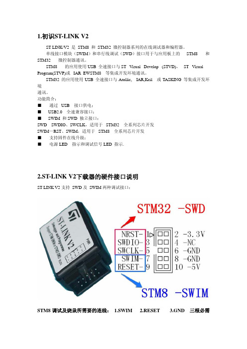
2.ST-LINK V2下载器的硬件接口说明
ST-LINK V2 支持 SWD 及 SWIM 两种调试接口:
STM8 调试及烧录所需要的连线: 1.SWIM 2.RESET 3.GND 三根必需
STM32 调试时所需要的线: 1.SWDIO 2.SWCLK
¾ NRST 接 STM32 的复位引脚 ¾ SWDIO 接 STM32 的 SWDIO 引脚 ¾ SWCLK 接 STM32 的 SWCLK 引脚 ¾ SWIM 为 STM8 调试烧录引脚 ¾ RESET 为 STM8 复位引脚 ¾ 3.3V 是内部 LDO 对外输出 3.3V 不要超过 300ma 的电流 ¾ 5V 是 USB 直接向外输出 5V ¾ 电源电流不要超过 400ma ¾ NC 为空引脚 ¾ GND 为电源地
设置你想要的配置(具体的配置字应用,可参考互联网技术资料),然后点击 (上方烧录工具图标左起第 2 个)进行烧录下载。
图标
8.其他注意事项
注意事项一: ST-LINK/V1 与 ST-LINK/V2 两个驱动模式完全不一样,如果您原来一直用
V1,换成 V2 后,需要重装安装 ST-LINK/V2 的驱动,并可能需要更新软件,也就是 说 ST-LINK/V1 和 V2 对电脑来说是完全不同的设备。
建立一个工程,OK 以后,点击图标 如下图:
,进入设置属性对话框,选择 Debug 选项卡。
在右上角的选项中进行如下选择。
然后点击 Settings。在跳出的对话框中进行如下选择(ort 中选择 SW),可以看到 SW Device信息框中出现目标芯片的信息。点击确定。
然后再打开 Utilities 选项卡并进行如下设置。 点击 Settings。进行如下图的设置:
5.1 ST-LINK V2 调试STM8
下面我们说一下如何使用 ST-link V2 来调试 STM8, 开发环境我们使用 STVD。使用 STVD开发环境及 ST-LINKV2 对 STM8 进行开发还需要进行一些简单的设置工作。 首先建立工程项目文件。如图
接下来,打开菜单“Debuginstrument”选择“TargetSettings”选项,进行如图所示的选择。 弹出如下选框:
ST-LINK V2 使用说明
目录
1.初识ST-LINK V2 ....................................................................................2 2.ST-LINK V2 下载器的硬件接口说明 ...................................................2 3.驱动安装与固件升级 .............................................................................3
3.1 驱动的安装 .............................................................................3 3.2 固件的升级 .............................................................................4 4.使用STM32 ST-LINK Utility 烧写目标板 hex....................................7 4.1 ST-LINK烧写hex文件 .............................................................7 5.使用ST-LINK V2 调试STM8 .................................................................8 5.1 ST-LINK V2 调试STM8 ..........................................................8 6.使用MDK进行STM32 的开发教程.....................................................10 6.1 ST-LINK V2 调试STM32 ......................................................10 7.使用STVP进行软件的下载..................................................................14 7.1 STVP下载程序.......................................................................14 7.2 STVP对STM8 OPTION配置.................................................18 8.其他注意事项 .......................................................................................18
使用 STM32 ST-LINKUtility 可以给 STM32 芯片烧写程序。使用的方法如下: 将 ST-LINKV2 和 STM32 目标板使用 SWD 接口连接,将 ST-LINKV2 和 计算机相连。 打开 STM32 ST-LINK Utilit 软件。在菜单栏中找到菜单项“Target”,点击子菜单 “connect”,在软件下方的状态栏会输出以下信息:
这样就成功下载了程序到我们的板子。
7.2 STVP对STM8 OPTION配置
STM8SMCU具有配置字 option,可以让开发者对芯片 GPIO 第二功能,内部看门 狗,时钟特性等进行配置,还可以令开发者对芯片程序进行上锁。
当需要使用时,通常我们运用 STVP软件对 MCU 配置字进行设置(通过 ST-LINK SWIM接口进行烧录)。打开 STVP软件,选择 MCU类型,点击下方 option选项卡, 我们将看到下图的各种配置字信息: