布赫Cindy系列平衡阀中文样本
布赫平衡阀培训
Bucher Hydraulics AG Neuheim, Switzerland Product Presentation Division MobileCompany and Product PresentationNovember 2008page 1Application Mobile CraneTelescope Winch (Hoist) Boom & DerrickingSlewing GearStabilisingCompany and Product PresentationNovember 2008page 6Load Control ValveCompany and Product PresentationNovember 2008page 10CINDY Load Control Valve• size 12 to 25 • maximum working pressure 420 bar • nominal flow up to 500 l/min • SAE, manifold or cartridge constructionCompany and Product PresentationNovember 2008page 11Available CoversActuatorCover PilotG cover Standard CoverCover D Dumping Covermechanical override includedCover H hydro-mechanical stroke limitermechanical override includedCover R hydraulic pressure reducing valveCover E electro-proportional pressure reducing valvePumpCompany and Product PresentationNovember 2008page 12Available CoversCover G Standard CoverCover D Dumping Covermechanical override includedCover H hydro-mechanical stroke limitermechanical override includedCover R hydraulic pressure reducing valveCover E electro-proportional pressure reducing valveCompany and Product PresentationNovember 2008page 13Available CoversCover G Standard CoverCover D Dumping Covermechanical override includedCover H hydro-mechanical stroke limitermechanical override includedCover R hydraulic pressure reducing valveCover E electro-proportional pressure reducing valvepiloted by currentCompany and Product PresentationNovember 2008page 14Typical Characteristic Curve B A (load control function)• CINDY 25 • Flow from Actuator back to tankS240 (e.g.) means, that the spool has around 30 bar back pressure at 240 l/min.Company and Product PresentationNovember 2008page 15Typical Characteristic Curve A B (check valve function)• CINDY 25 • Flow from pump to Actuator; the valve works as a check valve. • The pressure through the valve is only depend from the housing.Company and Product PresentationNovember 2008page 16OverviewCartridge only size 20 & 25. Cover R & E for CINDY 12 and manifold not applicable. For pressure relief valves (SVA, SVT, SVZ) please consult data sheets.Company and Product PresentationNovember 2008page 17Cindy Neutral Position“Valve leakfree closed”Load Pressure Pilot Spool Port BPilot Pressure Port XReturn Line Pressure Port ACompany and Product Presentation November 2008Pilot Control Spool Main Control Spoolpage 40Cindy Lifting Position“Function as a check valve”Load Pressure Pilot Spool Port BPilot Pressure Port XPump Pressure Port ACompany and Product Presentation November 2008Pilot Control Spool Main Control Spoolpage 41Cindy Neutral Position“Valve leakfree closed”Load Pressure Pilot Spool Port BPilot Pressure Port XReturn Line Pressure Port ACompany and Product Presentation November 2008Pilot Control Spool Main Control Spoolpage 42Cindy Lowering Start“Pre-opening”Load Pressure Pilot Spool Port BPilot Pressure Port XReturn Line Pressure Port ACompany and Product Presentation November 2008Pilot Control Spool Main Control Spoolpage 43Cindy Lowering Position“Open as a control valve”Load Pressure Pilot Spool Port BPilot Pressure Port XReturn Line Pressure Port ACompany and Product Presentation November 2008Pilot Control Spool Main Control Spoolpage 44Recommondations for Different Kind of ApplicationsCompany and Product PresentationNovember 2008page 45WINCHCompany and Product PresentationNovember 2008page 46Winch – Cover Kload er Y D v IN by C roove co g n i r . g Lowe lve with site side a oppo rol v cont ted from piloCompany and Product PresentationNovember 2008page 47Description Cover K• For non-vibrating winch function piloted from the opposite side • Leak oil at port DD1 must be drain off to tank without back pressuregroove DD1XCompany and Product Presentation November 2008 page 48BOOMCompany and Product PresentationNovember 2008page 49Boom –Cover R L o w e r i n g b y P A R A L L E L p i l o t e d m a i n c o n t r o l s p o o l a n d l o a d c o n t r o l v a l v e .•We recommend this cover for a compensated and overcompensated version •It requires a drain line back to tank with 0 (zero) bar•The maximum allowable inlet pressure at port X is 100 barBoom –Cover EL o w e r i n g b y E L E C T R O N I C p i l o t e d C I N D Y l o a d c o n t r o l v a l v e .Description Cover E•Gives the benefit of electro proportional control of a boom function •Leak oil at port DD1 must be drain off to tank without back pressure •The maximum allowable inlet pressure at port X is 50 barDescription Overcompensation (1)overcompensation orifice must be bigger than ∅1.2 mm!Description Overcompensation (2)valve must always be externally controlled (cover R or E).CINDY –Type CodeType CodeType CodeType Code -ExampleApplication:Winch lowering by a CINDY load control valve with a groove cover piloted from the opposite side .Pressure relief valve B to T; adjusted at 300 bar (max. 420 bar)Valve Series CINDY load control valve Nominal size 12; 16; 20; 25VersionSAE flange-mounted / seal material Nitrile / screws dacromate Flow rate200 l/min flow at circa 33 bar ∆p Influence of return line L = independent of back pressure in A Pilot controlling Damping cover with grooveOrifice combination12-40 bar; ZD = none; D1 = ∅0,6; By = ∅0,3Type Code -ExampleApplication:Winch lowering by a CINDY load control valve with a groove cover piloted from the opposite side .CINDY 20B SND S200L K 12-4SVT300Designfor AVR Valve and Electronic ControllerAVR ValveThe AVR system automatically reduces theamount of the displacement of the main controlspool, if the sum of the operated actuator flowbegins to exceed the available pump deliveryflow.The difference between available and requiredpump flow is detected by the AVR pressureregulator valve, which begins to reduce the pilotcontrol pressure feeding the proportional pilotvalves.The AVR system automatically reduces theamount of the displacement of the main controlspool, if the sum of the operated actuator flowbegins to exceed the available pump deliveryflow.The difference between available and requiredpump flow is detected by the AVR pressureregulator valve, which begins to reduce the pilotcontrol pressure feeding the proportional pilotvalves.AVR –Hydraulic CircuitPractical representation (example)Operating Example (1)Operating Example (2)condition: Q1 + Q2 + Q3 ≤p m Automatic Volumetric Flow Rate Reductionf l o w r a t e o f t h e v a l v e i n %255075100Electronic Controller -RecommendationsElectronic Data of SolenoidsCompany and Product PresentationNovember 2008page 76Control Characteristic(idealized)Company and Product PresentationNovember 2008page 77Setting of an Electronic ControllerCompany and Product PresentationNovember 2008page 78Different Configurations for AccelerationCompany and Product PresentationNovember 2008page 79Different Configurations for DecelerationCompany and Product PresentationNovember 2008page 80Thank you very much for your attention! Robert Kern Application ManagerCompany and Product Presentation November 2008 page 81。
Allen-Bradley

安装说明原版说明书译文Hiperface-to-DSL 反馈整流器套件产品目录号 2198-H2DCK变更摘要在后盖板增加了 EAC 徽标。
关于反馈整流器套件本套件适用于 Allen-Bradley® 2090 系列电机反馈电缆,且配备 10 个 Hiperface 编码器信号的接线端子。
Hiperface 编码器信号被转换成兼容的数字伺服链路 (DSL) 反馈信号。
必须为 10 针整流器套件连接器接线,并在正确放置电缆屏蔽层和电缆护套的情况下组装连接器壳体。
准备电缆如要将反馈整流器套件用于现有 Bulletin 2090 电缆,需要进行一些准备工作,以确保电缆屏蔽层、导线长度和剥线长度正确无误。
准备反馈电缆时,请遵循以下说明:•将屏蔽层修剪平整,以免绞线造成相邻端子短路。
•测量导线长度,确保其足够长,以提供工作回路。
•在每根导线上将剥掉足够长的屏蔽层,以提供合适的剥线长度。
反馈电缆尺寸单位为 mm (in.)在电缆护套上的位置2罗克韦尔自动化出版物 2198-IN006D-ZH-P - 2019年10 月Hiperface-to-DSL 反馈整流器套件安装整流器套件按照以下步骤安装整流器套件。
1.拆下保护盖,将信号线连接至合适的端子,为每个连接端留出工作回路。
有关 10 针端子插脚引线,请参见第 第3 页 页的 连接器数据。
2.以 0.25 N•m (2.2 lb•in) 的最大扭矩,拧紧端子螺丝。
3.将屏蔽夹夹到 12 mm (0.5in.) 的裸露电缆屏蔽层上,以在屏蔽编织层和屏蔽夹之间实现高效搭接。
4.连接扎带 (随套件一起提供),以消除应力。
5.以 0.3 N•m (2.6 lb•in) 的最大扭矩,拧紧屏蔽夹螺丝。
6.更换保护盖,然后安装保护盖螺丝。
以 0.3 N•m (2.6 lb•in) 的最大扭矩,拧紧保护盖螺丝。
7.将 2 针 DSL 连接器插入驱动连接器,然后将安装支架安装到其中一个安装位置 (共 3 个) 上。
汽车起重机平衡回路分析
5.方茴说:“那时候我们不说爱,爱是多么遥远、多么沉重的字眼啊。
我们只说喜欢,就算喜欢也是偷偷摸摸的。
”6.方茴说:“我觉得之所以说相见不如怀念,是因为相见只能让人在现实面前无奈地哀悼伤痛,而怀念却可以把已经注定的谎言变成童话。
”7.在村头有一截巨大的雷击木,直径十几米,此时主干上唯一的柳条已经在朝霞中掩去了莹光,变得普普通通了。
8.这些孩子都很活泼与好动,即便吃饭时也都不太老实,不少人抱着陶碗从自家出来,凑到了一起。
9.石村周围草木丰茂,猛兽众多,可守着大山,村人的食物相对来说却算不上丰盛,只是一些粗麦饼、野果以及孩子们碗中少量的肉食。
汽车起重机平衡回路分析一.前言在液压系统工作时,如果液压缸或液压马达的负荷为垂直水平的载荷,并且运动方向和重力与作用力方向一致时,就要用平衡阀使回路上产生油流阻力,防止运动失去控制。
平衡阀在液压起重机的起升、变幅和伸缩油路中应用较多。
例如在起升油路中,重物下降时,如果在起升马达的回路上没有设平衡阀,则在重力作用下,液压马达会越转越快,甚至产生事故。
平衡回路要求结构简单,闭锁性能好,工作可靠无冲击。
二.平衡回路作用任何平衡回路工作过程中,均有三种运动状态:即举重上升、承载静止、负载下行。
1.举重上伸在汽车起重机的伸缩、变幅、起伸3种机构中,平衡阀前端(油源方向)经高压软管与中心回转接头、操纵阀相连,后端经高压钢管与执行元件、液压缸或马达相连。
当机构运动方向与负载重力作用方向相反时,即当外伸、起升、变幅缸上举时,平衡阀只起通路作用,同时,执行元件有杆腔液压油经另一条油路流回油箱;当平衡阀与手动换向阀之间的管路(多为高压软管)损坏漏油时,平衡阀能封闭无杆腔油液,使负载停留在空中原位置不动,避免造成坠落事故,可起到安全保护作用。
2.承载静止当机构停止工作时,平衡阀内部油路被锁死封闭,其顺序阀也是完全关闭的,截止了执行元件的回油路,使机构和负载按需要停留在任意位置,称其为“位置锁定”。
BVS不锈钢平衡阀
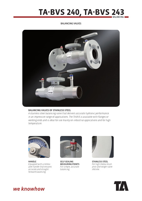
Balancing valvesBalancing valves OF sTainless sTeelA stainless steel balancing valve that delivers accurate hydronic performance in an impressive range of applications. The TA-BVS is available with flanges or welding ends and is ideal for use mainly on industrial applications and for hightemperature.HanDleEquipped with a remov-able handle that ensures accurate and straight-forward balancing.selF-sealingMeasURing POinTs For simple, accurate balancing.sTainless sTeel For high media resist-ance and longer valve lifetime.TecHnical DescRiPTiOnapplication:Heating and cooling systemsFunctions:Balancing Pre-setting Measuring Shut-offDimensions:DN 15-250Pressure class:Valve body: DN 15-50: PN 40DN 65-250: PN 25Flanges:DN 15-250: PN 16(PN 10, 25 and 40 on request)Temperature:Spindle seal, FPM (viton):Max. working temperature: 200°C Min. working temperature: 0°C Spindle seal, nitrile:Max. working temperature: 70°C Min. working temperature: -30°CTa-Bvs 240Ta-Bvs 243Note! Not for steam.Note! Not for steam.DN 15-50DN 65-250°CMPa34Material:Valve body: Stainless steel X2CrNiMo17-12-2 (1.4404) (EN 10217-7)Ball: Stainless steel X2CrNiMo17-12-2 (1.4404)Spindle: Stainless steel X2CrNiMo17-12-2 (1.4404)Spindle seal: FPM (viton) or nitrile Ball seal: Hardened PTFE (teflon)Handle: DN 15-150 stainless steel, DN 200-250 manual gear.Measuring points: Stainless steel X2CrNiMo17-12-2 (1.4404)Marking:Body and flanges: Traceability No.Label on body: TA, DN, PN, CE (according to table), material, max. temperature, product No and flow direction arrow.Flanges:EN 1092-1, ISO 7005-1.DN 15-50DN 65-250°C324Ta-Bvs 240Welding endsFPM (Viton)Nitrile*) Equipped with manual gear.Kvs = m 3/h at a pressure drop of 1 bar and fully open valve.Ta-Bvs 243FlangedFPM (Viton)Nitrile*) Equipped with manual gear.Kvs = m 3/h at a pressure drop of 1 bar and fully open valve.OPeRaTing insTRUcTiOn1. Locking screw2. Measuring points3. Removable handle4. Two O-rings. The upper can be replaced during operation.5. Ball with W-port. Equal percentage valve characteristic.MeasURing accURacy Deviation of flow at different settingsThe curve is valid for valves with normal pipe fittings. Try also to avoid mounting taps and pumps, immediately before thevalve.0,0 %5,0 %10,0 %15,0 %20,0 %25,0 %11,522,533,544,555,566,577,588,59*)*) Setting.2 D 5 D 2 D10 D5.3.4.sizingWhen D p and the design flow are known, use the formula to calculate the Kv-value or use the diagram.Kv valUesseTTing1. Adjust to the desired position (1).2. Open the locking screw of the limiter (2).3. Move the limiter against the edge of the scale plate (3).4. Tighten the locking screw of the limiter (2).Tour & Andersson retains the right to make changes to its products and specifications without prior notice.5-40-5 TA-BVS 240, TA-BVS 243 2008.05Dn 200-25011. Adjust to the desired position (1).。
паркер 二次泵气压力调节器 产品说明说明书
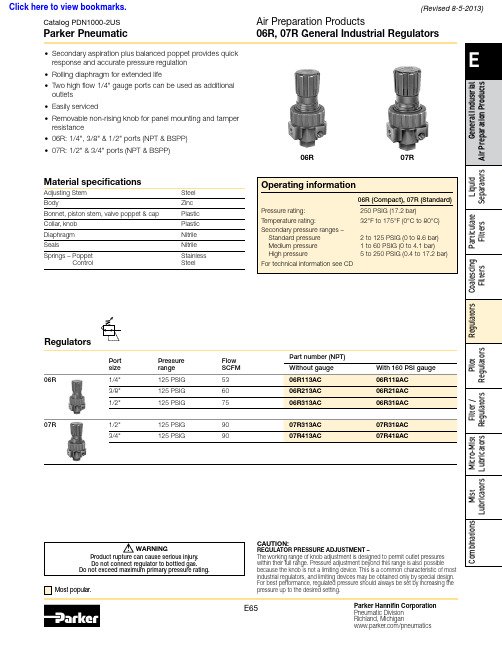
Catalog PDN1000-2USParker PneumaticAir Preparation Products06R, 07R General Industrial Regulators• Secondary aspiration plus balanced poppet provides quick response and accurate pressure regulation • Rolling diaphragm for extended life• Two high flow 1/4" gauge ports can be used as additional outlets • Easily serviced• Removable non-rising knob for panel mounting and tamper resistance • 06R: 1/4", 3/8" & 1/2" ports (NPT & BSPP)•07R: 1/2" & 3/4" ports (NPT & BSPP)06R07RRegulators Port Pressure Flow Part number (NPT)Material specificationsAdjusting Stem Steel BodyZinc Bonnet, piston stem, valve poppet & cap Plastic Collar, knob Plastic Diaphragm Nitrile SealsNitrile Springs – PoppetControlStainless Steel! WARNINGProduct rupture can cause serious injury.Do not connect regulator to bottled gas.Do not exceed maximum primary pressure rating.CAUTION:REGULATOR PRESSURE ADJUSTMENT –The working range of knob adjustment is designed to permit outlet pressures within their full range. Pressure adjustment beyond this range is also possiblebecause the knob is not a limiting device. This is a common characteristic of most industrial regulators, and limiting devices may be obtained only by special design. For best performance, regulated pressure should always be set by increasing the Click here to view bookmarks.(Revised 8-5-2013)Catalog PDN1000-2USParker PneumaticAir Preparation Products06R, 07R General Industrial Regulators(2)Service kits06R (Compact)07R (Standard)。
布赫Cindy系列平衡阀中文样本1
X
32页124部分
X
33页128部分
X
34页132部分
X
35页136部分
X
36页140部分
X
37页144部分
X
X
38页148部分
X
X
39页152部分
X
X
40页156部分
X
X
41页160部分
Cindy 20-B-S 350[l/min]
Cindy 25-B-S 500[l/min]
3/164
2. Cindy-12-B-S..-….-A-…-..型平衡阀产品说明
2.1 油口尺寸/重量
油口 A,A1 B X,MB
油口尺寸
G1/2″
SAE1/2″ 6000 psi
G1/4″
紧固转矩见 6 部分 Cindy 系列相关内容
2.2 标准型平衡阀
O 型圈 -
3.53×18.66 -
重量:大约 3.9Kg
27 A/F
24 A B
A1 1
28
安装面质量要求:
Rmax10
0.01/100mm
安全可靠的cindy系列平衡阀发展与进取1164目录页码1cindy系列产品b型阀选择表
安全可靠的 Cindy 系列平衡阀
发展与进取
1/164
目录
页码
1 Cindy系列产品B型阀选择表……………………………………………………………………………….……………….……….4 2 Cindy-12-B-S..-….-A-…-..型平衡阀产品说明…….…………………………………………………….………………….….5 3 Cindy-12-B-S..-….-L-…-..型平衡阀产品说明………………………………………………………….……….……………..9 4 Cindy-12-B-S..-….-A-…-..-SVA..型平衡阀产品说明……… ...…………………………….…….………..…………..….13 5 Cindy-12-B-S..-….-L-…-..-SVA..型平衡阀产品说明………………………………….………....…………………..……….17 6 Cindy-12-B-S..-….-L-…-..-SVT..型平衡阀产品说明…………………………………….…………..…….………….……..21 7 Cindy-12-B-S..-….-A-…-..-SVZ..型平衡阀产品说明……………………………….…….……………..……….…...………..25 8 Cindy-12-B-S..-….-L-…-..-SVZ..型平衡阀产品说明………………………………….……………………..…………………..29 9 Cindy-16-B-S..-….-A-…-..型平衡阀产品说明……………………………………….……….……..……….………….……….33 10 Cindy-16-B-S..-….-L-…-..型平衡阀产品说明……………………………….…………………...……..………….…………….37 11 Cindy-16-B-S..-….-A-…-..-SVA..型平衡阀产品说明…………………………………………...……………………….………41 12 Cindy-16-B-S..-….-L-…-..-SVA..型平衡阀产品说明……………………………………..……………..………………………45 13 Cindy-16-B-S..-….-L-…-..-SVT..型平衡阀产品说明…………………………………..……………………………..…………49 14 Cndy-16-B-S..-….-A-…-..-SVZ..型平衡阀产品说明…………………………………………………..…………………..……53 15 Cindy-16-B-S..-….-L-…-..-SVZ..型平衡阀产品说明………………………………..………………………………..…………57 16 Cindy-16-B-S..-….-L-…-..-..型平衡阀(负载压力补偿)产品说明……..……………………………………………………..…..61 17 Cindy-16-B-S..-….-L-…-..-..-SVA..型平衡阀(负载压力补偿)产品说明………………….…………..…………………..………65 18 Cindy-16-B-S..-….-L-…-..-..-SVT..型平衡阀(负载压力补偿)产品说明…….……………………………………….…………69 19 Cindy-16-B-S..-….-L-…-..-..-SVZ..型平衡阀(负载压力补偿)产品说明………………………..…………………...………….73 20 Cindy-20-B-S..-….-A-…-..型平衡阀产品说明……………………………………………………………………………….…77 21 Cindy-20-B-S..-….-L-…-..型平衡阀产品说明…………………………………………………………….………………….…81 22 Cindy-20-B-S..-….-A-…-..-SVA..型平衡阀产品说明………………………………………….………………………………85 23 Cindy-20-B-S..-….-L-…-..-SVA..型平衡阀产品说明……………………………………….…………………………………89 24 Cindy-20-B-S..-….-L-…-..-SVT..型平衡阀产品说明………………………………..…………………………………………93 25 Cindy-20-B-S..-….-A-…-..-SVZ..型平衡阀产品说明……………………………..…………………………………………97 26 Cindy-20-B-S..-….-L-…-..-SVZ.型平衡阀产品说明……………………………….………………………………….………101 27 Cindy-20-B-S..-….-L-…-..-..型平衡阀(负载压力补偿)产品说明…………………………………………………….……105 28 Cindy-20-B-S..-….-L-…-..-..-SVA..型平衡阀(负载压力补偿)产品说明….……………………………………….…….……109 29 Cindy-20-B-S..-….-L-…-..-..-SVT..型平衡阀(负载压力补偿)产品说明……………………………………….……….……113 30 Cindy-20-B-S..-….-L-…-..-..-SVZ..型平衡阀(负载压力补偿)产品说明……………………………………….………………117 31 Cindy-25-B-S..-….-A-…-..型平衡阀产品说明………………………………………...………………………....…………121 32 Cindy-25-B-S..-….-L-…-..型阀平衡阀产品说明…………………………………………...…………………….……………125 33 Cindy-25-B-S..-….-A-…-..-SVA..型平衡阀产品说明…………………………………...………………….…………………129 34 Cindy-25-B-S..-….-L-…-..-SVA..型平衡阀产品说明………………………………………………………….………………133 35 Cindy-25-B-S..-….-L-…-..-SVT..型平衡阀产品说明………………………………………………………….………………137 36 Cindy-25-B-S..-….-A-…-..-SVZ..型平衡阀产品说明………………………………………………………….………………141 37 Cindy-25-B-S..-….-L-…-..-SVZ..型平衡阀产品说明…………………………………………………………….……………145 38 Cindy-25-B-S..-….-L-…-..-..型平衡阀(负载压力补偿)产品说明……………………………………………………..………149 39 Cindy-25-B-S..-….-L-…-..-..-SVA..型平衡阀(负载压力补偿)产品说明………………………………………….….….……153 40 Cindy-25-B-S..-….-L-…-..-..-SVT..型平衡阀(负载压力补偿)产品说明…………………………………………..……….…157 41 Cindy-25-B-S..-….-L-…-..-..-SVZ..型平衡阀(负载压力补偿)产品说明………………………………………………………161
Parker Hannifin FDC101流量分配 合并阀门系列技术数据说明书

Manual Valves
Operating Temp. -40°C to +93.3°C (Nitrile)
SV
Range (Ambient) (-40°F to +200°F) -31.7°C to +121.1°C (Fluorocarbon)
(-25°F to +250°F)
Solenoid Valves
(3)
• Pressure compensated control in both directions
• 50/50 ratio standard, other ratios available on request
• FC
Commonly used for differential lock in transmission
B64 15.0 LPM ( 4 GPM) min. inlet 37.5 LPM (10 GPM) max. inlet 60% ‘4’ Port and 40% ‘2’ Port
D63 11.3 LPM (3 GPM) min. inlet 33.8 LPM (9 GPM) max. inlet 33% ‘4’ Port and 66% ‘2’ Port
B10-4-6T body — 6HP*50-S B10-4-8T body — 8HP*50-S B10-4-4P body — 102 x 4 B10-4-6P body — 102 x 6 B10-4-8P body — 102 x 8
When machining a manifold using the FDC101, use C10-4 cavity. Do not machine a port that directs flow to the nose of the cavity.
SERIES 4X高性能BRAY McCANNALOK阀门技术手册说明书

SERIES 4X HIGH PERFORMANCEBRA Y/McCANNALOK VAL VESTechnical ManualTHE HIGH PERFORMANCE COMPANYTABLE OF CONTENTSPart Numbering System 1 Seating & Unseating Torques 1 ASME 150 - Torques (Lb-in) 2 ASME 150 - Torques (Lb-in) 3 ASME 300 - Torques (Lb-in) 4 ASME 600 - Torques (Lb-in) 5 ASME 150 - Torques (N-m) 6 ASME 150 - Torques (N-m) 7 ASME 300 - Torques (N-m) 8 ASME 600 - Torques (N-m) 9 Dynamic Torques 10 Dynamic Torque Coefficient11 Subchoked and Choked Flow 12 Subchoked Liquid Flow, Line-size Valve 13 Choked Gas Flow, Reduced-size Valve 13 Maximum Allowable Stem Torques (Lb-in)* 14 Maximum Allowable Stem Torques (N-m)* 15 Valve Sizing Coefficients (Cv) 16 ASME 150 Series 40/41/4A - Valve Sizing Coefficient (Cv) 16 ASME 300 Series 42/43/4B - Valve Sizing Coefficient (Cv) 17 ASME 600 Series 44/45 - Valve Sizing Coefficient (Cv) 17 Valve Sizing Coefficients (Kv) 18 ASME 150 Series 40/41/4A - Valve Sizing Coefficient (Kv) 18 ASME 300 Series 42/43/4B - Valve Sizing Coefficient (Kv) 19 ASME 600 Series 44/45 - Valve Sizing Coefficient (Kv)19 Pressure-Temperature Charts - Standard McCannalok And Firesafe Valves20 Pressure-Temperature Charts - Metal Seated McCannalok Valves 22 Pressure Temperature Charts - Cryogenic McCannalok Valves 23 Examples of Typical Flange to Valve Bolting 24For information on this product and other Bray products please visit us at our web page - 1DOWNSTREAMUPSTREAMSEATING & UNSEATING TORQUESValve orientation to the flow of media affects the torque Torque values are presented in two categories:PART NUMBERING SYSTEMFor available valve sizes per ASMEClass 150, 300 & 600, refer to the DIMENSIONS charts.–EXAMPLE:41-1200-11001-46612 inch (300 mm), Lug Body, ASME Class 150 Mccannalok Valve with 466 Trim.All information herein is proprietary, confidential, and may not be copied or reproduced without the expressed written consent of BRAY INTERNATIONAL, Inc.The technical data herein is for general information only. Product suitability should be based solely upon customer’s detailed knowledge and experience with their application. The right to change or modify product design or product without prior notice is reserved.2All information herein is proprietary, confidential, and may not be copied or reproduced without the expressed written consent of BRAY INTERNATIONAL, Inc.The technical data herein is for general information only. Product suitability should be based solely upon customer’s detailed knowledge and experience with their application. The right to change or modify product design or product without prior notice is reserved. 3All information herein is proprietary, confidential, and may not be copied or reproduced without the expressed written consent of BRAY INTERNATIONAL, Inc.The technical data herein is for general information only. Product suitability should be based solely upon customer’s detailed knowledge and experience with their application. The right to change or modify product design or product without prior notice is reserved.4All information herein is proprietary, confidential, and may not be copied or reproduced without the expressed written consent of BRAY INTERNATIONAL, Inc.The technical data herein is for general information only. Product suitability should be based solely upon customer’s detailed knowledge and experience with their application. The right to change or modify product design or product without prior notice is reserved. 5All information herein is proprietary, confidential, and may not be copied or reproduced without the expressed written consent of BRAY INTERNATIONAL, Inc.The technical data herein is for general information only. Product suitability should be based solely upon customer’s detailed knowledge and experience with their application. The right to change or modify product design or product without prior notice is reserved.6All information herein is proprietary, confidential, and may not be copied or reproduced without the expressed written consent of BRAY INTERNATIONAL, Inc.The technical data herein is for general information only. Product suitability should be based solely upon customer’s detailed knowledge and experience with their application. The right to change or modify product design or product without prior notice is reserved. 7All information herein is proprietary, confidential, and may not be copied or reproduced without the expressed written consent of BRAY INTERNATIONAL, Inc.The technical data herein is for general information only. Product suitability should be based solely upon customer’s detailed knowledge and experience with their application. The right to change or modify product design or product without prior notice is reserved. 9All information herein is proprietary, confidential, and may not be copied or reproduced without the expressed written consent of BRAY INTERNATIONAL, Inc.The technical data herein is for general information only. Product suitability should be based solely upon customer’s detailed knowledge and experience with their application. The right to change or modify product design or product without prior notice is reserved.10DYNAMIC TORQUESWhen a media flows through a butterfly valve, static pressure does not act uniformly on the surfaces of the valve disc Dynamic torque will cause rotary motion when unchecked by the actuator or manual operator possibly resulting in opening or closing of the valve If the dynamic torque is of a magnitude that is greater than the bearing and packing friction torque and there is no actuator in place to maintain disc position, the opening or closing action could result in injury to operating personnel or an interruption of the process Sudden closure (slamming) can cause water hammer damage in lines carrying liquidIn high performance butterfly valves which have the disc offset from the stem and have non-symmetrical disc faces, dynamic torque acts to close the valve if the valve is installed with the seat retainer downstream, but can act to close or open the valve, depending on the position of the disc, if the seat retainer is upstream.Dynamic torque should be calculated as part of the valve actuator sizing procedure or to determine if hand lever operation is acceptable In this regard, the total torque of all service conditions must be consideredThe total torque when the disc is in the seat consists of:1 Seating torque2 Stem packing torque3 Eccentricity torque4 Stem bearing torqueThe total torque when the disc is in the seat is published as seating/unseating torque When the disc is out of the seat, the total torque consists of dynamic torque, stem packing torque, and stem bearing torqueTotal torque changes with the disc position Maximum total torque can occur at shutoff (disc in the seat), at breakaway (motion initiation), or at any open disc position where the product of valve pressure drop and dynamic torque coefficient peaks in combination with prevailing bearing and packing torqueEstimating Dynamic TorqueDynamic torque can be estimated using the following empirical equations:Liquid Flow:Imperial Td (Lb-in) = Ct D³ ❒p Metric Td (N-m) = 0001 Ct D³ ❒p Gas Flow:Imperial Td (Lb-in) = Ct D³ Y ❒p Metric Td (N-m) = 0001 Ct D³ Y ❒pPressure DistributionAll information herein is proprietary, confidential, and may not be copied or reproduced without the expressed written consent of BRAY INTERNATIONAL, Inc.The technical data herein is for general information only. Product suitability should be based solely upon customer’s detailed knowledge and experience with their application. The right to change or modify product design or product without prior notice is reserved.11DYNAMIC TORQUE COEFFICIENTFigure 1 - Seat Retainer DownstreamFigure 2 - Seat Retainer UpstreamAll information herein is proprietary, confidential, and may not be copied or reproduced without the expressed written consent of BRAY INTERNATIONAL, Inc.The technical data herein is for general information only. Product suitability should be based solely upon customer’s detailed knowledge and experience with their application. The right to change or modify product design or product without prior notice is reserved.12SUBCHOKED AND CHOKED FLOWAll information herein is proprietary, confidential, and may not be copied or reproduced without the expressed written consent of BRAY INTERNATIONAL, Inc.The technical data herein is for general information only. Product suitability should be based solely upon customer’s detailed knowledge and experience with their application. The right to change or modify product design or product without prior notice is reserved.13SUBCHOKED LIQUID FLOW, LINE-SIZE VALVE Thus the peak dynamic torque will occur between 30 and 40 degrees open Verify dynamic torque at 35 degrees:Approximate pressure drop = (70+35)/2 = 52 5 psi At 35 degrees: Td = 037 x 24³ x 52 5 = 27,000 Lb-inThe peak dynamic torque of approximately 27,000 Lb-in occurs at about 35 degrees open.When sizing the valve operator, total torque must be considered The total torque when the disc is in the seat consists of seating torque, stem packing torque, eccentricity torque and stem bearing torque The total torque when the disc is in the seat is published as seating/unseating torque (see pages 1-9 When the disc is out of the seat, total torque consists of dynamic torque, stem packing torque, andstem bearing torqueCHOKED GAS FLOW, REDUCED-SIZE VALVE14* Based on stem Material Code 54P (17-4 PH stainless steel, ASTM A564 Type 630 H1150D)MAXIMUM ALLOWABLE STEM TORQUES (Lb-in)*Standard, Fire Safe and Metal Seated Valves15* Based on stem Material Code 54P (17-4 PH stainless steel, ASTM A564 Type 630 H1150D)MAXIMUM ALLOWABLE STEM TORQUES (N-m)*Standard, Fire Safe and Metal Seated ValvesAll information herein is proprietary, confidential, and may not be copied or reproduced without the expressed written consent of BRAY INTERNATIONAL, Inc.The technical data herein is for general information only. Product suitability should be based solely upon customer’s detailed knowledge and experience with their application. The right to change or modify product design or product without prior notice is reserved.16VALVE SIZING COEFFICIENTS (Cv)• Cv stands for Valve Sizing Coefficient• Cv varies with the valve size, angle of opening and the manufacturer’s valve style•Cv is defined as the volume of water in USGPM that will flow through a given restriction or valve opening with apressure drop of one (1) psi at room temperatureAll information herein is proprietary, confidential, and may not be copied or reproduced without the expressed written consent of BRAY INTERNATIONAL, Inc.The technical data herein is for general information only. Product suitability should be based solely upon customer’s detailed knowledge and experience with their application. The right to change or modify product design or product without prior notice is reserved. 17All information herein is proprietary, confidential, and may not be copied or reproduced without the expressed written consent of BRAY INTERNATIONAL, Inc.The technical data herein is for general information only. Product suitability should be based solely upon customer’s detailed knowledge and experience with their application. The right to change or modify product design or product without prior notice is reserved.18VALVE SIZING COEFFICIENTS (Kv)• Kv stands for Valve Sizing Coefficient• Kv varies with the valve size, angle of opening and the manufacturer’s valve style•Kv is defined as the volume of water in Cubic Meters/Hour (m3/hr) that will flow through a given restriction or valve opening with a pressure drop of one (1) bar at room temperatureAll information herein is proprietary, confidential, and may not be copied or reproduced without the expressed written consent of BRAY INTERNATIONAL, Inc.The technical data herein is for general information only. Product suitability should be based solely upon customer’s detailed knowledge and experience with their application. The right to change or modify product design or product without prior notice is reserved. 19All information herein is proprietary, confidential, and may not be copied or reproduced without the expressed written consent of BRAY INTERNATIONAL, Inc.The technical data herein is for general information only. Product suitability should be based solely upon customer’s detailed knowledge and experience with their application. The right to change or modify product design or product without prior notice is reserved.20-2020040060080010001200140016000100200300400500600T e m p e r a t u r e ºFPressure psig-290100200204060801000T e m p e r a t u r e ºCPressure Bar300ASME 300ASME 600ASME 150Stainless Steel Body with RPTFESeatPressure psigAll information herein is proprietary, confidential, and may not be copied or reproduced without the expressed written consent of BRAY INTERNATIONAL, Inc.The technical data herein is for general information only. Product suitability should be based solely upon customer’s detailed knowledge and experience with their application. The right to change or modify product design or product without prior notice is reserved.21-2020040060080010001200140016000100200300400500600T e m p e r a t u r e ºFPressure psig-290100200204060801000T e m p e r a t u r e ºCPressure Bar300ASME 300ASME 600ASME 150Stainless Steel Body with PTFESeatPressure psig22SERIES 4X BRAY/McCANNALOK VALVESTECHNICAL MANUALT e m p e r a t u r e ºFPressure psigT e m p e r a t u r e ºCPressure BarCarbon Steel Body with Inconel ®Seat-2020040060080010001200140016000100200300400500600700800900T e m p e r a t u r e ºFPressure psigT e m p e r a t u r e ºCPressure BarStainless Steel Body with Inconel®Seat-200200400600800100012001400160002004006008001000Cryogenic Valve withFigure 5PRESSURE-TEMPERATURE CHARTS - METAL SEATED MCCANNALOK VALVESAll information herein is proprietary, confidential, and may not be copied or reproduced without the expressed written consent of BRAY INTERNATIONAL, Inc.The technical data herein is for general information only. Product suitability should be based solely upon customer’s detailed knowledge and experience with their application. The right to change or modify product design or product without prior notice is reserved.23SERIES 4X BRAY/McCANNALOK VALVEST e m p e r a t u r e ºFPressure psigT e m p e r a t u r e ºCPressure BarLow Temperature Valve withCarbon Steel Body and Polar ®Seat-60025*******150T e m p e r a t u r e ºFPressure psigT e m p e r a t u r e ºCPressure BarCryogenic Valve withStainless Steel Body and Polar ®Seat-200-3202004006008001000120014001600-100-50-150050100150-100-50-150-1960204060204060801000120ASME 300ASME 150ASME 300ASME 600ASME 150Figure 6PRESSURE TEMPERATURE CHARTS - CRYOGENIC MCCANNALOK VALVESAll information herein is proprietary, confidential, and may not be copied or reproduced without the expressed written consent of BRAY INTERNATIONAL, Inc.The technical data herein is for general information only. Product suitability should be based solely upon customer’s detailed knowledge and experience with their application. The right to change or modify product design or product without prior notice is reserved.24EXAMPLES OF TYPICAL FLANGE TO VALVE BOLTING*25TM-1023_S4X_06_2020All statements, technical information, and recommendations in this bulletin are for generaluse only. Consult Bray representatives or factory for the specific requirements and material selection for your intended application. The right to change or modify product design or product without prior notice is reserved. Patents issued and applied for worldwide.Bray ® is a registered trademark of Bray International, Inc.ENERGY Mining Oil & Gas PowerNuclear Power INDUSTRIAL Chemical Pulp & Paper Textile MarineWATERWater / Wastewater Ultra Pure Water Desalination IrrigationINFRASTRUCTURE Beverage & Food TransportationHeating, Ventilation & Air Conditioning (HVAC)BRAY FLOW CONTROL SOLUTIONS ARE AVAILABLE FOR A VARIETY OF INDUSTRIES.THE SMART CHOICE FOR FLOW CONTROL SINCE 1986. WITH MORE THAN 300 LOCATIONS WORLDWIDE, FIND A REPRESENTATIVE NEAR YOU AT US HEADQUARTERS Bray International, Inc.13333 Westland East Blvd.Houston, Texas 77041Tel: +1.281.894.5454EUROPE HEADQUARTERSBray Armaturen & Antriebe Europa Halskestraße 25D-47877 Willich GermanyTel: +49.173.1621.471CHINA HEADQUARTERSBray Controls (ZheJiang) Co. Limited 98 GaoXin #6 RoadXiaoShan Economic & Development Zone HangZhou, ZheJiang 311231, P .R. China Tel: +86.571.8285.2200INDIA HEADQUARTERSBray Controls India Pvt. Ltd.Plot No. H-18 & H-19, SIPCOT Industrial ParkVallam Vadagal, Echoor Post, Sriperumbudur Taluk Kancheepuram District, Tamil Nadu - 631 604Tel: +91.44.67170100© 2020 BRAY INTERNATIONAL, INC. All rights reserved.。
- 1、下载文档前请自行甄别文档内容的完整性,平台不提供额外的编辑、内容补充、找答案等附加服务。
- 2、"仅部分预览"的文档,不可在线预览部分如存在完整性等问题,可反馈申请退款(可完整预览的文档不适用该条件!)。
- 3、如文档侵犯您的权益,请联系客服反馈,我们会尽快为您处理(人工客服工作时间:9:00-18:30)。
95/16424.5 类型代号说明密封材料 腈橡胶 氟橡胶 低温橡胶用于基本阀的产品代号 300 6010216….. 300 6010284….. 300 6010330….. (无特殊性能)修理包先导控制G 型 修理包Cindy 20-B-S-N-2-G 修理包Cindy 20-B-S-V-2-G 修理包Cindy 20-B-S-T-2-G 产品代号 300.0306755 300.0306791 300.0306830 先导控制D,H 型 修理包Cindy 20-B-S-N-2-D 修理包Cindy 20-B-S-V-2-D 修理包Cindy 20-B-S-T-2-D 产品代号 300.0306756 300.0306792 300.0306831先导控制R 型 修理包Cindy20-B-S-N-2-R 修理包Cindy 20-B-S-V-2-R 修理包Cindy 20-B-S-T-2-R 产品代号 300.0306757 300.0306793 300.0306832 先导控制E 型 修理包Cindy20-B-S-N-2-E 只有腈橡胶密封 只有腈橡胶密封 产品代号 300.0306758备选法兰A 300.0306804 300.0306807 300.0306810阀系列 无泄漏负载控制阀 = CINDY 公称尺寸20㎜ = 20 类型B = B 应用/阀形式负载控制阀,用法兰直接连在执件上或管式连接 =S密封材料 温度范围腈橡胶(标准型) -20℃-80℃ =N 腈橡胶(低温型) -50℃-80℃ =T 氟橡胶 -20℃-200℃ =V 固定螺栓无固定螺栓 =O 非电镀螺栓 =S “Dacromate ”螺栓(防锈 =D 孔接口 ..= 形式1…99 (见9部分普通信息)先导控制种类 G ..= 先导控制带“标准盖” D..= 先导控制带“阻尼盖” H..= 先导控制带“机-液行程限制” R..= 先导控制带“减压阀” E..= 先导控制带“电磁比例减压阀”(仅有腈橡胶密封)(见9部分普通信息)回油(背压)对先导压力的影响 L= 与A 口的背压无关下降时流量(阀规格)S100= S100 S150= S150 S200= S200 S240= S240 S300= S30020CINDYBSL管螺纹法兰“A ”(可选择)B= G 1″ 二级压力溢流 SVT = 从B 口到T 口溢流(需油箱回油管) 管螺纹法兰“B ”(可选择)A= G 1″SVT压力设定 ..= 80到460bar96/16425. Cindy-20-B-S..-….-A-…-..-SVZ…型平衡阀产品说明25.1 油口尺寸/重量油口 油口尺寸 O 型圈 A,A2 SAE 1″ 6000 psi -B SAE 1″ 6000 psi 3.53×32.92 X,MB G1/4″ -紧固扭矩见6部分Cindy 系列相关内容 重量:大约7.6Kg25.2 标准型平衡阀系列号铭牌安装面质量要求:97/16425.3 先导型平衡阀(均可180°转位)带“阻尼盖”的先导控制 (D )带“机-液行程限制”的先导控制 (H )到B 口到B 口98/16425.4 性能曲线(测试时粘度为33mm 2/S[cSt]) 25.4.1 A→B压降(举升)流量[l/min] 25.4.2 B →A压降(下降,阀口全开)流量[l/min] 25.4.3 防爆溢流阀开启特性流量[l/min]压降[b a r ]压降[b a r ]压力[b a r ]设定值:500bar设定值:300bar99/16425.5 类型代号说明密封材料 腈橡胶 氟橡胶 低温橡胶用于基本阀的产品代号 300 6010217….. 300 6010285….. 300 6010331….. (无特殊性能)修理包先导控制G 型 修理包Cindy 20-B-S-N-1-G 修理包Cindy 20-B-S-V-1-G 修理包Cindy 20-B-S-T-1-G 产品代号 300.0306751 300.0306788 300.0306827 先导控制D,H 型 修理包Cindy20-B-S-N-1-D 修理包Cindy 20-B-S-V-1-D 修理包Cindy 20-B-S-T-1-D 产品代号 300.0306752 300.0306789 300.0306828 备选法兰A 300.0306804 300.0306807 300.0306810可选择SVZ 250-350 bar 250-350 bar 250-350 bar 300.6010408 300.6010409 300.6010410 350-500bar 350-500bar 350-500bar 300.6010411 300.6010412 300.6010413阀系列 无泄漏负载控制阀 = CINDY 公称尺寸16㎜ = 16 类型B = B 应用/阀形式负载控制阀,用法兰直接连在执件上或管式连接 =S 密封材料 温度范围腈橡胶(标准型) -20℃-80℃ =N 腈橡胶(低温型) -50℃-80℃ =T 氟橡胶 -20℃-200℃ =V 固定螺栓无固定螺栓 =O 非电镀螺栓 =S “Dacromate ”螺栓(防锈) =D 孔接口 ..= 形式 1…99 (见9部分普通信息)先导控制种类 G ..= 先导控制带“标准盖” D..= 先导控制带“阻尼盖” H..= 先导控制带“机-液行程限制” (见9部分普通信息)回油(背压)对先导压力的影响 A= 依靠A 口背压(先导压力需依靠背压的增加来产生,不需回油管路)下降时流量(阀规格)S100= S100 S150= S150 S200= S200 S240= S240 S300= S300. 20CINDYBSA管螺纹法兰“A ”(可选择)B= G 1″二级压力溢流 SVZ = 从B 口到L 口溢流公称尺寸:2.5mm 管螺纹法兰“B ”可选择A= G 1″ SVZ压力设定 ..= 80到460bar100/16426. Cindy-16-B-S..-….-L-…-..-SVZ 型平衡阀产品说明26.1 油口尺寸/重量油口 油口尺寸 O 型圈 A ,A1 SAE 1″ 6000 psi -B SAE 1″ 6000 psi 3.53×32.92 X,L,L1,L2,MB,MX G1/4″ -紧固扭矩见6部分Cindy 系列相关内容 重量:大约7.6Kg26.2标准型平衡阀系列号铭牌安装面质量要求:101/16426.4 先导型平衡阀(均可180°转位)到B 口到B 口102/16426.4 性能曲线(测试时粘度为33mm 2/S[cSt])26.4.1 A→B压降(举升)流量[l/min] 26.4.2 B →A压降(下降,阀口全开)流量[l/min] 26.4.3 防爆溢流阀开启特性流量[l/min]压降[b a r ]压降[b a r ]压力[b a r ]设定值:300bar设定值:500bar103/16426.5 类型代号说明密封材料 腈橡胶 氟橡胶 低温橡胶用于基本阀的产品代号 300 6010218….. 300 6010286….. 300 6010332….. (无特殊性能) 修理包先导控制G 型 修理包Cindy 20-B-S-N-1-G 修理包Cindy 20-B-S-V-1-G 修理包Cindy 20-B-S-T-1-G 产品代号 300.0306751 300.0306788 300.0306827 先导控制D,H 型 修理包Cindy 20-B-S-N-1-D 修理包Cindy 20-B-S-V-1-D 修理包Cindy 20-B-S-T-1-D 产品代号 300.0306752 300.0306789 300.0306828先导控制R 型 修理包Cindy20-B-S-N-1-R 修理包Cindy 20-B-S-V-1-R 修理包Cindy 20-B-S-T-1-R 产品代号 300.0306753 300.0306790 300.0306829 先导控制E 型 修理包Cindy20-B-S-N-1-E 只有腈橡胶密封 只有腈橡胶密封 产品代号 300.0306754备选法兰A 300.0306804 300.0306807 300.0306810 可选择SVZ 250-350 bar 250-350 bar 250-350 bar 300.6010408 300.6010409 300.6010410 350-500bar 350-500bar 350-500bar 300.6010411 300.6010412 300.6010413阀系列 无泄漏负载控制阀 = CINDY 公称尺寸16㎜ = 16 类型B = B 应用/阀形式负载控制阀,用法兰直接连在执件上或管式连接口 =S 密封材料 温度范围腈橡胶(标准型) -20℃-80℃ =N 腈橡胶(低温型) -50℃-80℃ =T 氟橡胶 -20℃-200℃ =V 固定螺栓无固定螺栓 =O 非电镀螺栓 =S “Dacromate ”螺栓(防锈) =D 孔接口 ..= 形式1…99 (见9部分普通信息)先导控制种类 G ..= 先导控制带“标准盖” D..= 先导控制带“阻尼盖” H..= 先导控制带“机-液行程限制” R..= 先导控制带“减压阀” E..= 先导控制带“电磁比例减压阀”(仅有腈橡胶密封)(见9部分普通信息)回油(背压)对先导压力的影响 L= 与A 口的背压无关(需油箱回油管)下降时流量(阀规格)S100= S100 S150= S150 S200= S200 S240= S240 S300= S30020CINDYBSL管螺纹法兰“A ”(可选择) B= G 1″二级压力溢流 SVZ = 从B 口到L 口溢流 (公称尺寸2.5mm)管螺纹法兰“B ”(可选择)A= G 1″ SVZ压力设定 ..= 250到500bar104/16427. Cindy-20-B-S..-….-L-…-..-..型平衡阀(负载压力补偿)产品说明27.1 油口尺寸/重量油口 油口尺寸 O 型圈 A ,A1 SAE 1″ 6000 psi -B SAE 1″ 6000 psi 3.53×32.92 X,L,L2,MB,MX G1/4″ -紧固扭矩见6部分Cindy 系列相关内容 重量:大约7.6Kg27.2标准型平衡阀系列号铭牌安装面质量要求:补偿节流孔105/16427.3 先导型平衡阀(均可180°转位)带“减压阀”的先导控制(R )带“电-液比例减压阀”的先导控制 (E )到B 口到B 口106/16427.4 性能曲线(测试时粘度为33m㎡/S[cSt])27.4.1 A→B压降(举升)流量[l/min] 27.4.2 B →A压降(下降,阀口全开)流量[l/min]压降[b a r ]压降[b a r ]107/16427.5 类型代号说明密封材料 腈橡胶 氟橡胶 低温橡胶 用于基本阀的产品代号 300 6010219….. 300 6010287….. 300 6010333….. (无特殊性能)修理包先导控制G 型 修理包Cindy 20-B-S-N-1-G 修理包Cindy 20-B-S-V-1-G 修理包Cindy 20-B-S-T-1-G 产品代号 300.0306751 300.0306788 300.0306827先导控制R 型 修理包Cindy20-B-S-N-1-R 修理包Cindy 20-B-S-V-1-R 修理包Cindy 20-B-S-T-1-R 产品代号 300.0306753 300.0306790 300.0306829 先导控制E 型 修理包Cindy20-B-S-N-1-E 只有腈橡胶密封 只有腈橡胶密封 产品代号 300.0306754 备选法兰A 300.0306804 300.0306807 300.0306810阀系列 无泄漏负载控制阀 = CINDY 公称尺寸20㎜ = 20 类型B = B 应用/阀形式负载控制阀,用法兰直接连在执件上或管式连接口 =S 密封材料 温度范围腈橡胶(标准型) -20℃-80℃ =N 腈橡胶(低温型) -50℃-80℃ =T 氟橡胶 -20℃-200℃ =V 固定螺栓无固定螺栓 =O 非电镀螺栓 =S “Dacromate ”螺栓(防锈) =D 孔接口 ..= 形式1…99 (见9部分普通信息)先导控制种类G ..= 先导控制带“标准盖” R..= 先导控制带“减压阀” E..= 先导控制带“电磁比例减压阀”(仅有腈橡胶密封)回油(背压)对先导压力的影响 L= 与A 口的背压无关(需油箱回油管)下降时流量(阀规格)S100= S100 S150= S150 S200= S200 S240= S240 S300= S30020CINDYBSL管螺纹法兰“A ”(可选择)B= G 1″可补偿(可选择) 25= 25%过补偿 50= 50%过补偿 管螺纹法兰“B ”(可选择) A= G 1″108/16428. Cindy-20-B-S..-….-L-…-..-..-SVA..型平衡阀(负载压力补偿)产品说明28.1 油口尺寸/重量油口 油口尺寸 O 型圈 A ,A1 SAE 1″6000 psi -B SAE 1″ 6000 psi 3.53×32.92 X,L,L2,MB,MX G1/4″ -紧固扭矩见6部分Cindy 系列相关内容 重量:大约7.5Kg28.2 标准型平衡阀系列号铭牌安装面质量要求:补偿节流孔109/16428.3 先导型平衡阀(均可180°转位)带“减压阀”的先导控制 (R )带“电-液比例减压阀”的先导控制 (E )到B 口到B 口110/16428.4 性能曲线(测试时粘度为33mm 2/S[cSt]) 28.4.1 A→B压降(举升)流量[l/min] 28.4.2 B →A压降(下降,阀口全开)流量[l/min] 28.4.3 二级溢流阀开启特性流量[l/min]压降[b a r ]压降[b a r ]设定压力:250bar设定压力:380barB 口负载压力[b a r ]111/16428.5 类型代号说明密封材料 腈橡胶 氟橡胶 低温橡胶用于基本阀的产品代号 300 6010220….. 300 6010288….. 300 6010334….. (无特殊性能)修理包先导控制G 型 修理包Cindy 20-B-S-N-1-G 修理包Cindy 20-B-S-V-1-G 修理包Cindy 20-B-S-T-1-G 产品代号 300.0306751 300.0306788 300.0306827 先导控制R 型 修理包Cindy 20-B-S-N-1-R 修理包Cindy 20-B-S-V-1-R 修理包Cindy 20-B-S-T-1-R 产品代号 300.0306753 300.0306790 300.0306829 先导控制E 型 修理包Cindy 20-B-S-N-1-E 只有腈橡胶密封 只有腈橡胶密封 产品代号 300.0306754备选法兰A 300.0306804 300.0306807 300.0306810阀系列 无泄漏负载控制阀 = CINDY 公称尺寸20㎜ = 20 类型B = B 应用/阀形式负载控制阀,用法兰直接连在执件上或管式连接 =S 密封材料 温度范围腈橡胶(标准型) -20℃-80℃ =N 腈橡胶(低温型) -50℃-80℃ =T 氟橡胶 -20℃-200℃ =V 固定螺栓无固定螺栓 =O 非电镀螺栓 =S “Dacromate ”螺栓(防锈) =D 孔接口 ..= 形式1…99 (见9部分普通信息)先导控制种类 G ..= 先导控制带“标准盖” R..= 先导控制带“减压阀” E..= 先导控制带“电磁比例减压阀”(仅有腈橡胶密封)(见9部分普通信息)回油(背压)对先导压力的影响 L= 与A 口的背压无关(需油箱回油管)下降时流量(阀规格)S100= S100 S150= S150 S200= S200 S240= S240 S300= S30020CINDYBSL管螺纹法兰“A ”(可选择)B= G 1″可补偿(可选择)25= 25%过补偿 50= 50%过补偿管螺纹法兰“B ”(可选择)A= G 1″ 二级压力溢流从B 口溢流到A 口SV A = (需油箱回油管) SV A压力设定 ...= 80-460bar112/16429. Cindy-20-B-S..-….-L-…-..-..-SVT..型平衡阀(负载压力补偿)产品说明29.1 油口尺寸/重量油口 油口尺寸 O 型圈 A SAE 1″6000 psi -B SAE 1″ 6000 psi 3.53×32.92 T G3/4″ - X,L2,MB,MX G1/4″ -紧固扭矩见6部分Cindy 系列相关内容 重量:大约7.6Kg29.2 标准型平衡阀系列号铭牌安装面质量要求:补偿节流孔113/16429.3 先导型平衡阀(均可180°转位)带“减压阀”的先导控制 (R )带“电-液比例减压阀”的先导控制 (E )到B 口到B 口114/16429.4 性能曲线(测试时粘度为33mm 2/S[cSt])29.4.1 A→B压降(举升)流量[l/min] 29.4.2 B →A压降(下降,阀口全开)流量[l/min] 29.4.3 二级溢流阀开启特性流量[l/min]压降[b a r ]压降[b a r ]设定压力:380bar设定压力:250bar115/16429.5 类型代号说明密封材料 腈橡胶 氟橡胶 低温橡胶用于基本阀的产品代号 300 6010221….. 300 6010289….. 300 6010335….. (无特殊性能)修理包先导控制G 型 修理包Cindy 20-B-S-N-2-G 修理包Cindy 20-B-S-V-2-G 修理包Cindy 20-B-S-T-2-G 产品代号 300.0306755 300.0306791 300.0306830 先导控制R 型 修理包Cindy 20-B-S-N-2-R 修理包Cindy 20-B-S-V-2-R 修理包Cindy 20-B-S-T-2-R 产品代号 300.0306757 300.0306793 300.0306832 先导控制E 型 修理包Cindy 20-B-S-N-2-E 只有腈橡胶密封 只有腈橡胶密封 产品代号 300.0306758备选法兰A 300.0306804 300.0306807 300.0306810阀系列 无泄漏负载控制阀 = CINDY 公称尺寸20㎜ = 20 类型B = B 应用/阀形式负载控制阀,用法兰直接连在执件上或管式连接口 =S 密封材料 温度范围腈橡胶(标准型) -20℃-80℃ =N 腈橡胶(低温型) -50℃-80℃ =T 氟橡胶 -20℃-200℃ =V 固定螺栓无固定螺栓 =O 非电镀螺栓 =S “Dacromate ”螺栓(防锈) =D 孔接口 ..= 形式1…99 (见9部分普通信息)先导控制种类 G ..= 先导控制带“标准盖” R..= 先导控制带“减压阀” E..= 先导控制带“电磁比例减压阀”(仅有腈橡胶密封)(见9部分普通信息)回油(背压)对先导压力的影响 L= 与A 口的背压无关下降时流量(阀规格)S100= S100 S150= S150 S200= S200 S240= S240 S300= S30020CINDYBSL管螺纹法兰“A ” (可选择) B= G 1″可补偿(可选择) 25= 25%过补偿 50= 50%过补偿 管螺纹法兰“B ”(可选择)A= G 1″二级压力溢流从B 口到T 口溢流SVT = (需油箱回油管)SVT压力设定 ...= 80-460bar116/16430. Cindy-20-B-S..-….-L-…-..-..-SVZ..型平衡阀(负载压力补偿)产品说明30.1 油口尺寸/重量油口 油口尺寸 O 型圈 A,A1 SAE 1″ 6000 psi -B SAE 1″ 6000 psi 3.53×32.92 X,L,L1,L2,MB,MX G1/4″ -紧固扭矩见6部分Cindy 系列相关内容 重量:大约7.6Kg30.2 标准型平衡阀系列号铭牌安装面质量要求:补偿节流孔117/16430.3 先导型平衡阀(均可180°转位)带“减压阀”的先导控制 (R )带“电-液比例减压阀”的先导控制 (E )到B 口到B 口118/16430.4 性能曲线(测试时粘度为33mm 2/S[cSt])30.4.1 A→B压降(举升)流量[l/min] 30.4.2 B →A压降(下降,阀口全开)流量[l/min] 30.4.3 防爆溢流阀开启特性流量[l/min]压降[b a r ]压降[b a r ]压力[b a r ]设定压力:300bar设定压力:500bar119/16430.5 类型代号说明密封材料 腈橡胶 氟橡胶 低温橡胶用于基本阀的产品代号 300 6010222….. 300 6010290….. 300 6010336….. (无特殊性能)修理包先导控制G 型 修理包Cindy 20-B-S-N-1-G 修理包Cindy 20-B-S-V-1-G 修理包Cindy 20-B-S-T-1-G 产品代号 300.0306751 300.0306788 300.0306827 先导控制R 型 修理包Cindy 20-B-S-N-1-R 修理包Cindy 20-B-S-V-1-R 修理包Cindy 20-B-S-T-1-R 产品代号 300.0306753 300.0306790 300.0306829 先导控制E 型 修理包Cindy 20-B-S-N-1-E 只有腈橡胶密封 只有腈橡胶密封 产品代号 300.0306754备选法兰A 300.0306804 300.0306807 300.0306810 可选SVZ 250-350bar 250-350bar 250-350bar 300.6010408 300.6010409 300.6010410 350-500bar 350-500bar 350-500bar 300.6010411 300.6010412 300.6010413阀系列 无泄漏负载控制阀 = CINDY 公称尺寸20㎜ = 20 类型B = B 应用/阀形式负载控制阀,用法兰直接连在执件上或管式连接口 =S 密封材料 温度范围腈橡胶(标准型负载控制阀) -20℃-80℃ =N腈橡胶(低温型) -50℃-80℃ =T 氟橡胶 -20℃-200℃ =V 固定螺栓无固定螺栓 =O 非电镀螺栓 =S “Dacromate ”螺栓(防锈) =D 孔接口 ..= 形式1…99 (见9部分普通信息)先导控制种类 G ..= 先导控制带“标准盖” R..= 先导控制带“减压阀” E..= 先导控制带“电磁比例减压阀”(仅有腈橡胶密封)(见9部分普通信息)回油(背压)对先导压力的影响 L= 与A 口的背压无关(需油箱回油管)下降时流量(阀规格)S100= S100 S150= S150 S200= S200 S240= S240 S300= S30020CINDYBSL管螺纹法兰 “A ”(可选择) B= G 1″过补偿(可选择) 25= 25%过补偿 50= 50%过补偿 管螺纹法兰“B ”(可选择) A= G 1″ 二级压力溢流从B 口到L 口溢流SVZ = (公称尺寸2.5mm) SVZ压力设定 ...= 80-460bar120/16431. Cindy-25-B-S..-….-A-…-..型平衡阀产品说明31.1 油口尺寸/重量油口 油口尺寸 O 型圈 A,A1 SAE1 1/4″ 6000 psi -B SAE1 1/4″ 6000 psi 3.53×37.69 X,,MB, G1/4″ -紧固扭矩见6部分Cindy 系列相关内容 重量:大约13.9Kg31.2 标准型平衡阀系列号铭牌安装面质量要求:121/16431.3 先导型平衡阀(均可180°转位)带“阻尼盖”的先导控制 (D )带“机-液行程限制”的先导控制 (H )到B 口到B 口122/16431.4 性能曲线(测试时粘度为33m㎡/S[cSt]) 31.4.1 A→B压降(举升)流量[l/min] 31.4.2 B →A压降(下降,阀口全开)流量[l/min]压降[b a r ]压降[b a r ]123/16431.5 类型代号说明密封材料 腈橡胶 氟橡胶 低温橡胶用于基本阀的产品代号 300 6010223….. 300 6010291….. 300 6010337….. (无特殊性能)修理包先导控制G 型 修理包Cindy 25-B-S-N-1-G 修理包Cindy 25-B-S-V-1-G 修理包Cindy 25-B-S-T-1-G 产品代号 300.0306759 300.0306794 300.0306833 先导控制D,H 型 修理包Cindy 25-B-S-N-1-D 修理包Cindy 25-B-S-V-1-D 修理包Cindy 25-B-S-T-1-D 产品代号 300.0306760 300.0306795 300.0306834可选法兰A 300.0306805 300.0306808 300.0306811阀系列 无泄漏负载控制阀 = CINDY 公称尺寸25㎜ = 25 类型B = B 应用/阀形式负载控制阀,用法兰直接连在执件上或管式连接口 =S 密封材料 温度范围腈橡胶(标准型) -20℃-80℃ =N 腈橡胶(低温型) -50℃-80℃ =T 氟橡胶 -20℃-200℃ =V 固定螺栓无固定螺栓 =O 非电镀螺栓 =S “Dacromate ”螺栓(防锈) =D孔接口 ..= 形式1…99 (见9部分普通信息)先导控制种类 G ..= 先导控制带“标准盖” D..= 先导控制带“阻尼盖” H..= 先导控制带“机-液行程限制” (见9部分普通信息)回油(背压)对先导压力的影响 A= 依靠A 口背压(先导压力需依靠背压的增加来产生,不需回油管路)下降时流量(阀规格) S250= S250 S400= S400 S500= S50025CINDYBSA管螺纹法兰“A ”(可选择)B= G 1 1/4″ 管螺纹法兰“B ”(可选择)A= G 1 1/4″124/16432. Cindy-25-B-S..-….-L-…-..型平衡阀产品说明32.1 油口尺寸/重量油口 油口尺寸 O 型圈A ,A1 SAE 1 1/4″ 6000 psi -B SAE 1 1/4″ 6000 psi 3.53×37.92 X,L,L2,MB,MX G1/4″ -紧固扭矩见6部分Cindy 系列相关内容 重量:大约13.9Kg32.2标准型平衡阀系列号铭牌安装面质量要求:125/16432.3 先导型平衡阀(均可180°转位)126/16432..4 性能曲线(测试时粘度为33mm 2/S[cSt]) 32.4.1 A→B压降(举升)流量[l/min] 32.4.2 B →A压降(下降,阀口全开)流量[l/min]压降[b a r ]压降[b a r ]127/16432.5 类型代号说明密封材料 腈橡胶 氟橡胶 低温橡胶用于基本阀的产品代号 300 6010224….. 300 6010292….. 300 6010338….. (无特殊性能)修理包先导控制G 型 修理包Cindy 25-B-S-N-1-G 修理包Cindy 25-B-S-V-1-G 修理包Cindy 25-B-S-T-1-G 产品代号 300.0306759 300.0306794 300.0306833 先导控制D,H 型 修理包Cindy25-B-S-N-1-D 修理包Cindy 25-B-S-V-1-D 修理包Cindy 25-B-S-T-1-D 产品代号 300.0306760 300.0306795 300.0306834 先导控制R 型 修理包Cindy 25-B-S-N-1-R 修理包Cindy 25-B-S-V-1-R 修理包Cindy 25-B-S-T-1-R 产品代号 300.0306761 300.0306796 300.0306835 先导控制E 型 修理包Cindy 25-B-S-N-1-E 只有腈橡胶密封 只有腈橡胶密封 产品代号 300.0306762可选法兰A 300.0306805 300.0306808 300.0306811阀系列 无泄漏负载控制阀 = CINDY 公称尺寸25㎜ = 25 类型B = B 应用/阀形式负载控制阀,用法兰直接连在执件上或管式连接口 =S 密封材料 温度范围腈橡胶(标准型) -20℃-80℃ =N 腈橡胶(低温型) -50℃-80℃ =T 氟橡胶 -20℃-200℃ =V 固定螺栓无固定螺栓 =O 非电镀螺栓 =S “Dacromate ”螺栓(防锈) =D孔接口..= 形式1 (99)(见9部分普通信息) 先导控制种类 G ..= 先导控制带“标准盖”D..= 先导控制带“阻尼盖”H..= 先导控制带“机-液行程限制”R..= 先导控制带“减压阀”E..= 先导控制带“电控比例减压阀” (仅有腈橡胶密封)(见9部分普通信息) 回油(背压)对先导压力的影响L= 和A 口背压无关(需回油管路)下降时流量(阀规格)S250= S250 S400= S400 S500= S500 25CINDYBSL管螺纹法兰“A ” (可选择)B= G 1/4″ 管螺纹法兰“B ”(可选择)A= G 1/4″128/16433. Cindy-25-B-S..-….-A-…-..SVA…型平衡阀产品说明33.1 油口尺寸/重量油口 油口尺寸 O 型圈 A ,A1 SAE1 1/4″ 6000 psi -B SAE 1 1/4″ 6000 psi 3.53×37.69 X,MB G1/4″ -紧固扭矩见6部分Cindy 系列相关内容 重量:大约13.7Kg33.2 标准型平衡阀系列号铭牌安装面质量要求:129/16433.3 先导型平衡阀(均可180°转位)带“阻尼盖”的先导控制 (D )带“机-液行程限制”的先导控制 (H )到B 口到B 口130/16433.4 性能曲线(测试时粘度为33m㎡/S[cSt]) 33.4.1 A→B压降(举升)流量[l/min] 33.4.2 B →A压降(下降,阀口全开)流量[l/min] 33.4.3 二级溢流阀开启特性流量[l/min]压降[b a r ]压降[b a r ]设定压力:3800bar设定压力:250bar设定压力:250bar B 口负载压力[b a r ]131/16433.5 类型代号说明密封材料 腈橡胶 氟橡胶 低温橡胶用于基本阀的产品代号 300 6010225….. 300 6010293….. 300 60103339….. (无特殊性能)修理包先导控制G 型 修理包Cindy 25-B-S-N-2-G 修理包Cindy 25-B-S-V-2-G 修理包Cindy 25-B-S-T-2-G 产品代号 300.0306763 300.0306797 300.0306836 先导控制D,H 型 修理包Cindy 25-B-S-N-2-D 修理包Cindy 25-B-S-V-2-D 修理包Cindy 25-B-S-T-2-D 产品代号 300.0306764 300.0306798 300.0306837备选法兰A 300.0306805 300.0306808 300.0306811阀系列 无泄漏负载控制阀 = CINDY 公称尺寸25㎜ = 25 类型B = B 应用/阀形式负载控制阀,用法兰直接连在执件上或管式连接口 =S 密封材料 温度范围腈橡胶(标准型) -20℃-80℃ =N 腈橡胶(低温型) -50℃-80℃ =T 氟橡胶 -20℃-200℃ =V 固定螺栓无固定螺栓 =O 非电镀螺栓 =S “Dacromate ”螺栓(防锈) =D 孔接口 ..= 形式1…99 (见9部分普通信息)先导控制种类 G ..= 先导控制带“标准盖”D..= 先导控制带“阻尼盖”H..= 先导控制带“机-液行程限制”(见9部分普通信息)回油(背压)对先导压力的影响A= 依靠A 口背压(先导压力需依靠背压的增加来产生,不需回油管路)下降时流量(阀规格)S250= S250 S400= S400 S500= S50025CINDYBSA管螺纹法兰“A ”(可选择)B= G 3/4″ 二级压力溢流 SV A = 从B 口向A 口溢流管螺纹法兰“B ”(可选择)A= G 3/4″SV A压力设定 ..= 80到460bar132/16434. Cindy-25-B-S..-….-L-…-..-SVA…型平衡阀产品说明34.1 油口尺寸/重量油口 油口尺寸 O 型圈 A ,A1 SAE1 1/4″ 6000 psi -B SAE 3/4″ 6000 psi 3.53×37.69 X,L,L2,MB,MX G1/4″ -紧固扭矩见6部分Cindy 系列相关内容 重量:大约13.7Kg34.2 标准型平衡阀系列号铭牌安装面质量要求:133/16412.3先导型平衡阀(均可180°转位)134/16434.4 性能曲线(测试时粘度为33m㎡/S[cSt]) 34.4.1 A→B压降(举升)流量[l/min] 34.4.2 B →A压降(下降,阀口全开)流量[l/min] 34.4.3 二级溢流阀开启特性流量[l/min]压降[b a r ]压降[b a r ]设定压力:380bar设定压力:250barB 口负载压力[b a r ]135/16434.5 类型代号说明密封材料 腈橡胶 氟橡胶 低温橡胶用于基本阀的产品代号 300 6010226….. 300 6010294….. 300 6010340….. (无特殊性能)修理包先导控制G 型 修理包Cindy 25-B-S-N-2-G 修理包Cindy 25-B-S-V-2-G 修理包Cindy 25-B-S-T-2-G 产品代号 300.0306763 300.0306797 300.0306836 先导控制D,H 型 修理包Cindy 25-B-S-N-2-D 修理包Cindy 25-B-S-V-2-D 修理包Cindy 25-B-S-T-2-D 产品代号 300.0306764 300.0306798 300.0306837先导控制R 型 修理包Cindy25-B-S-N-2-R 修理包Cindy 25-B-S-V-2-R 修理包Cindy 25-B-S-T-2-R 产品代号 300.0306765 300.0306799 300.0306838 先导控制E 型 修理包Cindy25-B-S-N-2-E 只有腈橡胶密封 只有腈橡胶密封 产品代号 300.0306766备选法兰A 300.0306805 300.0306808 300.0306811阀系列 无泄漏负载控制阀 = CINDY 公称尺寸25㎜ = 25 类型B = B 应用/阀形式负载控制阀,用法兰直接连在执件上或管式连接口 =S 密封材料 温度范围腈橡胶(标准型) -20℃-80℃ =N 腈橡胶(低温型) -50℃-80℃ =T 氟橡胶 -20℃-200℃ =V 固定螺栓无固定螺栓 =O 非电镀螺栓 =S “Dacromate ”螺栓(防锈) =D孔接口 ..= 形式1…99 (见9部分普通信息) 先导控制种类 G ..= 先导控制带“标准盖”D..= 先导控制带“阻尼盖”H..= 先导控制带“机-液行程限制”R..= 先导控制带“减压阀”E..= 先导控制带“电控比例减压阀” (仅有腈橡胶密封) (见9部分普通信息)回油(背压)对先导压力的影响 L= 与A 口的背压无关(需油箱回油管)下降时流量(阀规格)S250= S250S400= S400 S500= S50025CINDYBSL管螺纹法兰“A ”(可选择)B= G1 1/4″ 二级压力溢流 SV A = 从B 口到A 口溢流管螺纹法兰“B ”(可选择)A= G1 1/4″SV A压力设定 ..= 80到460bar136/16435. Cindy-25-B-S..-….-L-…-..-SVT…型平衡阀产品说明35.1 油口尺寸/重量油口 油口尺寸 O 型圈 A,A1 SAE1 1/4″ 6000 psi -B SAE1 1/4″ 6000 psi 3.53×37.69 T,T1 G3/4″ - X,L2,MB,MX G1/4″ -紧固扭矩见6部分Cindy 系列相关内容 重量:大约13.4Kg35.2 标准型平衡阀系列号铭牌安装面质量要求:137/16413.3 先导型平衡阀(均可180°转位)到B 口138/16435.4 性能曲线(测试时粘度为33m㎡/S[cSt]) 35.4.1 A→B压降(举升)流量[l/min] 35.4.2 B →A压降(下降,阀口全开)流量[l/min] 35.4.3 二级溢流阀开启特性流量[l/min]压降[b a r ]压降[b a r ]设定压力:250bar设定压力:380barB 口负载压力[b a r ]139/16435.5 类型代号说明密封材料 腈橡胶 氟橡胶 低温橡胶用于基本阀的产品代号 300 6010227….. 300 6010295….. 300 6010341….. (无特殊性能)修理包先导控制G 型 修理包Cindy 25-B-S-N-3-G 修理包Cindy 25-B-S-V-3-G 修理包Cindy 25-B-S-T-3-G 产品代号 300.0306767 300.0306800 300.0306839 先导控制D,H 型 修理包Cindy 25-B-S-N-3-D 修理包Cindy 25-B-S-V-3-D 修理包Cindy 25-B-S-T-3-D 产品代号 300.0306768 300.0306801 300.0306840 先导控制R 型 修理包Cindy 25-B-S-N-3-R 修理包Cindy 25-B-S-V-3-R 修理包Cindy 25-B-S-T-3-R 产品代号 300.0306769 300.0306802 300.0306841 先导控制E 型 修理包Cindy 25-B-S-N-3-E 只有腈橡胶密封 只有腈橡胶密封 产品代号 300.0306770备选法兰A 300.0306805 300.0306808 300.0306811阀系列 无泄漏负载控制阀 = CINDY 公称尺寸25㎜ = 25 类型B = B 应用/阀形式负载控制阀,用法兰直接连在执件上或管式连接口 =S 密封材料 温度范围腈橡胶(标准型) -20℃-80℃ =N 腈橡胶(低温型) -50℃-80℃ =T 氟橡胶 -20℃-200℃ =V 固定螺栓无固定螺栓 =O 非电镀螺栓 =S “Dacromate ”螺栓(防锈) =D孔接口 ..= 形式1…99 (见9部分普通信息) 先导控制种类 G ..= 先导控制带“标准盖”D..= 先导控制带“阻尼盖”H..= 先导控制带“机-液行程限制”R..= 先导控制带“减压阀”E..= 先导控制带“电磁比例减压阀”(仅有腈橡胶密封)(见9部分普通信息)回油(背压)对先导压力的影响 L= 与A 口的背压无关(需油箱回油管)下降时流量(阀规格)S250= S250S400= S400S500= S50025CINDYBSL管螺纹法兰“A ”(可选择)B= G 1 1/4″ 二级压力溢流 SVT = 从B 口向T 口溢流(需油箱回油管)管螺纹法兰“B ”(可选择)A= G 1 1/4″ SVT压力设定 ..= 80到460bar140/16436. Cindy-25-B-S..-….-A-…-..-SVZ…型平衡阀产品说明36.1 油口尺寸/重量油口 油口尺寸 O 型圈 A,A1 SAE1 1/4″ 6000 psi -B SAE1 1/4″ 6000 psi 3.53×37.69 X,MB G1/4″ -紧固扭矩见6部分Cindy 系列相关内容 重量:大约13.9Kg36.2 标准型平衡阀系列号铭牌安装面质量要求:141/16436.3 先导型平衡阀(均可180°转位)带“阻尼盖”的先导控制 (D )带“机-液行程限制”的先导控制 (H )到B 口到B 口142/16436.4 性能曲线(测试时粘度为33m㎡/S[cSt]) 36.4.1 A→B压降(举升)流量[l/min] 36.4.2 B →A压降(下降,阀口全开)流量[l/min] 36.4.3 防爆溢流阀开启特性流量[l/min]压降[b a r ]压降[b a r ]压力[b a r ]设定压力:500bar设定压力:300bar143/16436.5 类型代号说明密封材料 腈橡胶 氟橡胶 低温橡胶用于基本阀的产品代号 300 6010228….. 300 6010296….. 300 6010342….. (无特殊性能)修理包先导控制G 型 修理包Cindy 25-B-S-N-1-G 修理包Cindy 25-B-S-V-1-G 修理包Cindy 25-B-S-T-1-G 产品代号 300.0306759 300.0306794 300.0306833 先导控制D,H 型 修理包Cindy 25-B-S-N-1-D 修理包Cindy 25-B-S-V-1-D 修理包Cindy 25-B-S-T-1-D 产品代号 300.0306760 300.0306795 300.0306834备选法兰A 300.0306805 300.0306808 300.0306811 可选择SVZ 250-350 bar 250-350 bar 250-350 bar 300.6010408 300.6010409 300.6010410 350-500bar 350-500bar 350-500bar 300.6010411 300.6010412 300.6010413阀系列 无泄漏负载控制阀 = CINDY 公称尺寸25㎜ = 25 类型B = B 应用/阀形式负载控制阀,用法兰直接连在执件上或管式连接口 =S 密封材料 温度范围腈橡胶(标准型) -20℃-80℃ =N 腈橡胶(低温型) -50℃-80℃ =T 氟橡胶 -20℃-200℃ =V 固定螺栓无固定螺栓 =O 非电镀螺栓 =S “Dacromate ”螺栓(防锈) =D 孔接口 ..= 形式1…99 (见9部分普通信息)先导控制种类 G ..= 先导控制带“标准盖”D..= 先导控制带“阻尼盖”H..= 先导控制带“机-液行程限制”(见9部分普通信息)回油(背压)对先导压力的影响 A= 依靠A 口背压(先导压力需依靠背压的增加来产生,不需回油管路)下降时流量(阀规格)S250= S250 S400= S400 S500= S50025CINDYBSA管螺纹法兰“A ”(可选择)B= G1 1/4″ 二级压力溢流 SVZ = 从B 口向L 口溢流 (公称尺寸:2.5mm )管螺纹法兰“B ”(可选择)A= G1 1/4″ SVZ压力设定 ..= 250到500bar144/16437. Cindy-25-B-S..-….-L-…-..-SVZ 型平衡阀产品说明37.1 油口尺寸/重量油口 油口尺寸 O 型圈 A ,A1 SAE 1 1/4″ 6000 psi -B SAE 1 1/4″ 6000 psi 3.53×37.69 X,L,L1,L2,MB,MX G1/4″ -紧固扭矩见6部分Cindy 系列相关内容 重量:大约13.9Kg37.2标准型平衡阀系列号铭牌安装面质量要求:。