调度绞车论文中英文对照资料外文翻译文献
气动绞车外文翻译

毕业论文(设计)外文文献翻译学院:专业:机械设计制造及其自动化学号:0942823215姓名:指导教师:2013年 4 月 10 日JT调度绞车Davis, C. S, S. M Ggllager, and M. S Berman设计和初步结果拱水生生物学京能集团摘要调度绞车及其结构特点调度绞车是常用来调度车辆及进行辅助牵引作业的一种绞车。
常用于矿井巷道中拖运矿车及辅助搬运,也可用在采掘工作面、装车站调度空、重载矿车。
调度绞车是一种全齿传动机械。
齿轮传动系统又称轮系。
根据轮系传动时各齿轮轴线在空间的相对位置是否固定,可分为定轴轮系和周转轮系。
定轴轮系又有外啮合圆柱齿轮传动和内啮合圆柱齿轮传动之分,而周转轮系又有差动传动和行星传动之分。
调度绞车的传动齿轮既有内啮合圆柱齿轮传动,又有行星传动,所以调度绞车又称内齿轮行星传动绞车。
调度绞车常用型号主要有JD—0.4(JD—4.5)、JD—1(JD)—11.4)、JD—1.(JD—22)、JD—2(JD—25)、JD—3(JD—40)等。
下面以JD—3(即JD—40)型调度绞车为例介绍调度绞车的组成及传动原理。
(一)JD—3型调度绞车的组成JD—3型调度绞车的主要组成部分为滚筒、制动装置机座和电动机。
绞车滚筒由铸钢制成,其主要功能是缠绕钢丝绳牵引负荷。
滚筒内和大内齿轮下装有减速齿轮。
绞车上共装有两组带式闸,即制动闸2,工作闸3。
电动机一侧的制动闸2用来制动滚筒,大内齿轮上的工作闸3用于控制Z7组运转。
机座用铸铁制成,电动机轴承支架及闸带定位板等均用螺栓固定在机座上。
电动机为专用隔爆三相笼型电动机。
(二)JD—3型调度绞车的传动原理该型绞车采用两级内啮合传动和一级行星轮传动。
Z1/Z2和Z3/Z4为两级内啮合传动,Z5、Z6、Z7组成行星传动机构。
在电动机5轴头上安装着加长套的齿轮Z1,通过内齿轮Z2、齿轮Z3和内齿轮Z4,把运动传到齿轮Z5上,齿轮Z5是行星轮系的中央轮(或称太阳轮),再带动两个行星齿轮Z6和大内齿轮Z7。
带式输送机及其牵引系统外文文献翻译、中英文翻译
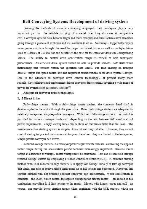
Belt Conveying Systems Development of driving systemAmong the methods of material conveying employed,belt conveyors play a very important part in the reliable carrying of material over long distances at competitive cost.Conveyor systems have become larger and more complex and drive systems have also been going through a process of evolution and will continue to do so.Nowadays,bigger belts require more power and have brought the need for larger individual drives as well as multiple drives such as 3 drives of 750 kW for one belt(this is the case for the conveyor drives in Chengzhuang Mine).The ability to control drive acceleration torque is critical to belt conveyors’ performance.An efficient drive system should be able to provide smooth,soft starts while maintaining belt tensions within the specified safe limits.For load sharing on multiple drives.torque and speed control are also important considerations in the drive system’s design. Due to the advances in conveyor drive control technology,at present many more reliable.Cost-effective and performance-driven conveyor drive systems covering a wide range of power are available for customers’ choices[1].1 Analysis on conveyor drive technologies1.1 Direct drivesFull-voltage starters.With a full-voltage starter design,the conveyor head shaft is direct-coupled to the motor through the gear drive.Direct full-voltage starters are adequate for relatively low-power, simple-profile conveyors.With direct full-voltage starters.no control is provided for various conveyor loads and.depending on the ratio between fu11- and no-1oad power requirements,empty starting times can be three or four times faster than full load.The maintenance-free starting system is simple,low-cost and very reliable.However, they cannot control starting torque and maximum stall torque;therefore.they are limited to the low-power, simple-profile conveyor belt drives.Reduced-voltage starters.As conveyor power requirements increase,controlling the applied motor torque during the acceleration period becomes increasingly important.Because motor torque 1s a function of voltage,motor voltage must be controlled.This can be achieved through reduced-voltage starters by employing a silicon controlled rectifier(SCR).A common starting method with SCR reduced-voltage starters is to apply low voltage initially to take up conveyor belt slack.and then to apply a timed linear ramp up to full voltage and belt speed.However, this starting method will not produce constant conveyor belt acceleration.When acceleration is complete.the SCRs, which control the applied voltage to the electric motor.are locked in full conduction, providing fu11-line voltage to the motor.Motors with higher torque and pull—up torque,can provide better starting torque when combined with the SCR starters, which areavailable in sizes up to 750 KW.Wound rotor induction motors.Wound rotor induction motors are connected directly to the drive system reducer and are a modified configuration of a standard AC induction motor.By inserting resistance in ser ies with the motor’s rotor windings.the modified motor control system controls motor torque.For conveyor starting,resistance is placed in series with the rotor for low initial torque.As the conveyor accelerates,the resistance is reduced slowly to maintain a constant acceleration torque.On multiple-drive systems.an external slip resistor may be left in series with the rotor windings to aid in load sharing.The motor systems have a relatively simple design.However, the control systems for these can be highly complex,because they are based on computer control of the resistance switching.Today,the majority of control systems are custom designed to meet a conveyor system’s particular specifications.Wound rotor motors are appropriate for systems requiring more than 400 kW .DC motor.DC motors.available from a fraction of thousands of kW ,are designed to deliver constant torque below base speed and constant kW above base speed to the maximum allowable revolutions per minute(r/min).with the majority of conveyor drives, a DC shunt wound motor is used.Wherein the motor’s rotating armature is connected externally.The most common technology for controlling DC drives is a SCR device.which allows for continual variable-speed operation.The DC drive system is mechanically simple, but can include complex custom-designed electronics to monitor and control the complete system.This system option is expensive in comparison to other soft-start systems.but it is a reliable, cost-effective drive in applications in which torque,1oad sharing and variable speed are primary considerations.DC motors generally are used with higher-power conveyors,including complex profile conveyors with multiple-drive systems,booster tripper systems needing belt tension control and conveyors requiring a wide variable-speed range.1.2 Hydrokinetic couplingHydrokinetic couplings,commonly referred to as fluid couplings.are composed of three basic elements; the driven impeller, which acts as a centrifugal pump;the driving hydraulic turbine known as the runner and a casing that encloses the two power components.Hydraulic fluid is pumped from the driven impeller to the driving runner, producing torque at the driven shaft.Because circulating hydraulic fluid produces the torque and speed,no mechanical connection is required between the driving and driven shafts.The power produced by this coupling is based on the circulated fluid’s amount and density and the torque in proportion to input speed.Because the pumping action within the fluid coupling depends on centrifugal forces.the output speed is less than the input speed.Referred to as slip.this normally is betweenl% and 3%.Basic hydrokinetic couplings are available in configurations from fractional to several thousand kW .Fixed-fill fluid couplings.Fixed-fill fluid couplings are the most commonly used soft-start devices for conveyors with simpler belt profiles and limited convex/concave sections.They are relatively simple,1ow-cost,reliable,maintenance free devices that provide excellent soft starting results to the majority of belt conveyors in use today.Variable-fill drain couplings.Drainable-fluid couplings work on the same principle as fixed-fill couplings.The coupling’s impellers are mounted on the AC motor and the runners on the driven reducer high-speed shaft.Housing mounted to the drive base encloses the working circuit.The coupling’s rotating casing contains bleed-off orifices that continually allow fluid to exit the working circuit into a separate hydraulic reservoir.Oil from the reservoir is pumped through a heat exchanger to a solenoid-operated hydraulic valve that controls the filling of the fluid coupling.To control the starting torque of a single-drive conveyor system,the AC motor current must be monitored to provide feedback to the solenoid control valve.Variable fill drain couplings are used in medium to high-kW conveyor systems and are available in sizes up to thousands of kW .The drives can be mechanically complex and depending on the control parameters.the system can be electronically intricate.The drive system cost is medium to high, depending upon size specified.Hydrokinetic scoop control drive.The scoop control fluid coupling consists of the three standard fluid coupling components:a driven impeller, a driving runner and a casing that encloses the working circuit.The casing is fitted with fixed orifices that bleed a predetermined amount of fluid into a reservoir.When the scoop tube is fully extended into the reservoir, the coupling is l00 percent filled.The scoop tube, extending outside the fluid coupling,is positioned using an electric actuator to engage the tube from the fully retracted to the fully engaged position.This control provides reasonably smooth acceleration rates.to but the computer-based control system is very complex.Scoop control couplings are applied on conveyors requiring single or multiple drives from l50 kW to 750 kW.1.3 Variable-frequency control(VFC)Variable frequency control is also one of the direct drive methods.The emphasizing discussion about it here is because that it has so unique characteristic and so good performance compared with other driving methods for belt conveyor.VFC devices Provide variable frequency and voltage to the induction motor, resulting in an excellent starting torque and acceleration rate for belt conveyor drives.VFC drives.available from fractional to several thousand(kW ), are electronic controllers that rectify AC line power to DC and,through aninverter, convert DC back to AC with frequency and voltage contro1.VFC drives adopt vector control or direct torque control(DTC)technology,and can adopt different operating speeds according to different loads.VFC drives can make starting or stalling according to any given S-curves.realizing the automatic track for starting or stalling curves.VFC drives provide excellent speed and torque control for starting conveyor belts.and can also be designed to provide load sharing for multiple drives.easily VFC controllers are frequently installed on lower-powered conveyor drives,but when used at the range of medium-high voltage in the past.the structure of VFC controllers becomes very complicated due to the limitation of voltage rating of power semiconductor devices,the combination of medium-high voltage drives and variable speed is often solved with low-voltage inverters using step-up transformer at the output,or with multiple low-voltage inverters connected in series.Three-level voltage-fed PWM converter systems are recently showing increasing popularity for multi-megawatt industrial drive applications because of easy voltage sharing between the series devices and improved harmonic quality at the output compared to two-level converter systems With simple series connection of devices.This kind of VFC system with three 750 kW /2.3kV inverters has been successfully installed in ChengZhuang Mine for one 2.7-km long belt conveyor driving system in following the principle of three-level inverter will be discussed in detail.2 Neutral point clamped(NPC)three-level inverter using IGBTsThree-level voltage-fed inverters have recently become more and more popular for higher power drive applications because of their easy voltage sharing features.1ower dv/dt per switching for each of the devices,and superior harmonic quality at the output.The availability of HV-IGBTs has led to the design of a new range of medium-high voltage inverter using three-level NPC topology.This kind of inverter can realize a whole range with a voltage rating from 2.3 kV to 4.1 6 kV Series connection of HV-IGBT modules is used in the 3.3 kV and 4.1 6 kV devices.The 2.3 kV inverters need only one HV-IGBT per switch[2,3].2.1 Power sectionTo meet the demands for medium voltage applications.a three-level neutral point clamped inverter realizes the power section.In comparison to a two-level inverter.the NPC inverter offers the benefit that three voltage levels can be supplied to the output terminals,so for the same output current quality,only 1/4 of the switching frequency is necessary.Moreover the voltage ratings of the switches in NPC inverter topology will be reduced to 1/2.and the additional transient voltage stress on the motor can also be reduced to 1/2 compared to that of a two-level inverter.The switching states of a three-level inverter are summarized in Table 1.U.V and Wdenote each of the three phases respectively;P N and O are the dc bus points.The phase U,for example,is in state P(positive bus voltage)when the switches S1u and S2u are closed,whereas it is in state N (negative bus voltage) when the switches S3u and S4u are closed.At neutral point clamping,the phase is in O state when either S2u or S3u conducts depending on positive or negative phase current polarity,respectively.For neutral point voltage balancing,the average current injected at O should be zero.2.2 Line side converterFor standard applications.a l2-pulse diode rectifier feeds the divided DC-link capacitor.This topology introduces low harmonics on the line side.For even higher requirements a 24-pulse diode rectifier can be used as an input converter.For more advanced applications where regeneration capability is necessary, an active front.end converter can replace the diode rectifier, using the same structure as the inverter.2.3 Inverter controlMotor Contro1.Motor control of induction machines is realized by using a rotor flux.oriented vector controller.Fig.2 shows the block diagram of indirect vector controlled drive that incorporates both constant torque and high speed field-weakening regions where the PW M modulator was used.Inthis figure,the command flux is generated as function of speed.The feedback speed isadded with the feed forward slip command signal . the resulting frequency signal isintegrated and then the unit vector signals(cos and sin)are generated.The vector rotatorgenerates the voltage and angle commands for the PW M as shown.PWM Modulator.The demanded voltage vector is generated using an elaborate PWM modulator.The modulator extends the concepts of space-vector modulation to the three-level inverter.The operation can be explained by starting from a regularly sampled sine-triangle comparison from two-level inverter.Instead of using one set of reference waveforms and one triangle defining the switching frequency,the three-level modulator uses two sets of reference waveforms U r1and U r2and just one triangle.Thus, each switching transition is used in an optimal way so that several objectives are reached at the same time.Very low harmonics are generated.The switching frequency is low and thus switching losses are minimized.As in a two-level inverter, a zero-sequence component can be added to each set of reference waveform s in order to maximize the fundamental voltage component.As an additional degree of freedom,the position of the reference waveform s within the triangle can be changed.This can be used for current balance in the two halves of the DC-1ink.3 Testing resultsAfter Successful installation of three 750 kW /2.3 kV three-level inverters for one 2.7 km long belt conveyor driving system in Chengzhuang Mine.The performance of the whole VFC system was tested.Fig.3 is taken from the test,which shows the excellent characteristic of the belt conveyor driving system with VFC controller.Fig.3 includes four curves.The curve 1 shows the belt tension.From the curve it can be find that the fluctuation range of the belt tension is very smal1.Curve 2 and curve 3 indicate current and torque separately.Curve 4 shows the velocity of the controlled belt.The belt velocity have the“s”shape characteristic.A1l the results of the test show a very satisfied characteristic for belt driving system.4 ConclusionsAdvances in conveyor drive control technology in recent years have resulted in many more reliable.Cost-effective and performance-driven conveyor drive system choices for users.Among these choices,the Variable frequency control (VFC) method shows promising use in the future for long distance belt conveyor drives due to its excellent performances.The NPC three-level inverter using high voltage IGBTs make the Variable frequency control in medium voltage applications become much more simple because the inverter itself can provide the medium voltage needed at the motor terminals,thus eliminating the step-up transformer in most applications in the past.The testing results taken from the VFC control system with NPC three.1evel inverters used in a 2.7 km long belt conveyor drives in Chengzhuang Mine indicates that the performance of NPC three-level inverter using HV-IGBTs together with the control strategy of rotor field-oriented vector control for induction motor drive is excellent for belt conveyor driving system.带式输送机及其牵引系统在运送大量的物料时,带式输送机在长距离的运输中起到了非常重要的竞争作用。
电力绞车的控制外文翻译、中英文翻译、外文文献翻译

英文原文Electrical Winch Controlsby Tom Young The form of motor control we all know best is the simple manual station with up and down pushbuttons. While these stations may still be the perfect choice for certain applications, a dizzying array of more sophisticated controls is also available. This article addresses the basic electrical requirements of the motors and user interface issues you will need to address before spcifying, building or buying winch controls.begin with, the manual control stations should be of the hold-to-run type,so that if you take your finger off of the button the winch stops. Additionally,every control station needs an emergency stop (E-stop) that kills all power to the winch, not just the control circuit. Think about it—if the win ch isn’t stopping when it should, you really need a failsafe way to kill the line power. It’s also a great idea to have a key operated switch on control stations,especially where access to the stations is not controlled.Safe operation by authorized personnel must be considered when designing even the simplest manual controls.Controlling Fixed Speed MotorsThe actual controlling device for a fixed speed winch is a three phase reversing starter. The motor is reversed by simply switching the phase sequence from ABC to CBA. This is accomplished by two three-pole contactors, interlocked, so they can’t both be closed at the same time. The NEC requires both overload and short circuit protection. To protect the motor from overheating due to mechanical overloads a thermal overload relay is built into the starter. This has bi-metallic strips that match the heating pattern of the motor and trips contacts when they overheat. Alternatively, a thermistor can be mounted in the motor winding tomonitor the motor temperature. Short circuit protection is generally provided by fuses rated for use with motors.A separate line contactor should be provided ahead of the reversing contactor for redundancy. This contactor is controlled by the safety circuits: E-stop and overtravel limits.This brings us to limit switches. When you get to the normal end of travel limit the winch stops and you can only move it in the opposite direction (away from the limit). There also needs to be an overtravel limit in case, due to an electrical or mechanical problem, the winch runs past the normal limit. If you hit an overtravel limit the line contactor opens so there is no way to drive off ofthe limits. If this occurs, a competent technician needs to fix the problem that resulted in hitting the overtravel limit. Then, you can override the overtravels using the spring return toggle switch inside the starter—as opposed to using jumpers or hand shooting the contactors.Variable Speed RequirementsOf course, the simple fixed speed starter gets replaced with a variable speed drive. Here’s where things start to get interesting! At the very least you need to add a speed pot to the control station. A joystick is a better operator interface,as it gives you a more intuitive control of the moving piece.Unfortunately,you can’t just order any old variable speed drive from your local supplier and expect it to raise and lower equipment safely and reliably over kids on stage. Most variable speed drives won’t,as they aren’t designed for lifting. The drive needs to be set up so that torque is developed at the motor before the brake is released, and (when stopping) the brake is set before torque is taken away.For many years DC motors and drives provided a popular solution as they allowed for good torque at all speeds. The large DC motors required for most winches are expensive, costing many times what a comparable AC motor costs. However, the early AC drives were not very useful, as they had a very limited speed range and produced low torque at low speeds. More recently, as the AC drives improved,the low cost and plentiful availability of AC motors resulted in a transition to AC drives.There are two families of variable speed AC drives. Variable frequency inverters are well known and readily available. These drives convert AC to DC,then convert itback to AC with a different frequency. If the drive produces 30 Hz, a normal 60 Hz motor will run at half speed. In theory this is great, but in reality there are a couple of problems. First, a typical 60 Hz motor gets confused at a line frequency below 2 or 3 Hz, and starts to cog (jerk and sputter), or just stops.This limits you to a speed range of as low as 20:1—hardly suitable for subtle effects on stage! Second, many lower cost inverters are also incapable of providing full torque at low speeds. Employing such drives can result in jerky moves, or a complete failure to lift the piece—exactly what you don’t want to see when you are trying to start smoothly lifting a scenic element. Some of the newer inverters are closed loop (obtain feedback from the motor to provide more accurate speed control) and will work quite well.The other family of AC drives is flux vector drives. These units require an encoder mounted on the motor shaft allowing the drive to precisely monitor the rotation of the armature. A processor determines the exact vector of magnetic flux (thus flux vector drive) required to rotate the armature the next few degrees at a given speed. These drives allow an infinite speed range, as you can actually produce full torque at zero speed. The precise speed and position control offered by these drives make them a favorite in high performance applications.PLC-based controls provide system status as well as control options. This screen give the operator full acces s to Carnegie Hall’s nine stage floor lifts. PLC Based SystemsA PLC is a programmable logic controller. First developed to replace the relay based industrial control systems of the ’50s and ’60s, these controls are at home in rugged, industrial environments. These are modular systems with a great variety of I/O modules allowing semi-custom hardware configurations to be assembled easily at a reasonable price. These include position control modules,counters, A/D and D/A converters and all sorts of solid state or hard contact closure outputs. The great variety of I/O components and the modular nature of the PLC make this an effective way to build custom and semi-custom control systems.The greatest drawback to PLC systems is the lack of really great displays to tell you what they are doing or to help you program them. Monochrome and medium resolution color displays are the norm, as the primary use for these components in on a factory floor.One of the first major PLC systems used in a large entertainment venue is thecomplex lift and wagon system at the original MGM Grand (now Bally’s) in Las Vegas. Several manufacturers offer standard PLC-based systems and a host of semi-custom acoustic banner, shell, and lift control systems is also available. The ability to build custom systems from standard building blocks is the greatest strength of PLC-based controls.High End ControllersThe most sophisticated rigging controllers go well beyond speed, time, and position control. They include the ability to write complex cues, record profiled moves, and manage multiple cues running at once.Many of the larger opera houses are moving toward point hoist systems, where there is a separate winch for each lift line (the rigging equivalent of dimmer per cir cuit). When multiple winches are used to carry a single piece, the winches must be perfectly synchronized, or the load can shift so that an individual winch can become dangerously overloaded. The control system must be able to keep selected winches in synch or provide a rapid, coordinated stop if a winch is unable to stay in synch with the others. With a typical top speed of of each other 240 fpm and a requirement to keep the winches within a 1/8″, you have less than three milliseconds to recognize a problem, attempt to correct the errant winch’s speed,determine that you’ve failed and initiate a coordinated stop of all the winches in the group. This takes a lot of computing, fast I/O, and well-written software.There are two very different approaches to large rigging control systems. Originally, a single console was used, with the usual problem of where it should be located for the operator’s optimum view. Unfortunately this can change not only from show to show, but also from one cue to the next. This dilemma has been partially addressed by using video cameras at different locations in conjunction with 3D screen graphics that allow the operator to view the expected rigging motion three dimensionally from any viewpoint. This allows the operator to view the on screen movement of the rigging from a viewpoint that matches his actual view of the stage, or the actual view of a closed circuit camera. For complex moves with inter-related pieces this makes the control and understanding of what is happening much simpler.The other approach is a distributed system, with several portable consoles. This allows different operators to control different aspects of the rigging, in the same manner we have done with manual sets. A dramatic example of this approach is used by the Royal Opera at Covent Garden, where there are ten consoles controlling a total of 240 motors. Each console has five playbacks, and is set up so that each motor is assigned to a single console. One operator and console could control everything, but frequently one console may be running stage lifts,another the onstage rigging, and a third is being used backstage to move stored drops.Cutting-edge portable consoles allow multiple operators to control the action from the best vantage points and provide 3D displays.Reprinted from PROTOCOL, the Journal of the Entertainment Services and Technology Association () Fall 2003 issue. ©2003 ESTA. ConclusionThe tremendous variety of rigging control systems currently available ranges from the pushbutton station to complex multi-user computerized control system. When shopping for rigging control systems you generally get what you pay for. The most important features are safety and reliability. These are features with real value, and you should expect to pay a fair price for this security. Work with an established manufacturer who can show you working installations and who will put you in contact with users who have requirements similar to yours.中文译文电力绞车的控制对于电动机的控制,我们所知道的最好的方式就是使用由许多点动式按钮组成的简单的手工操作台。
机床的论文中英文资料外文翻译文献
机床的论文中英文资料外文翻译文献引言机床是制造业中重要的设备,用于加工各种零部件和制造产品。
本文汇总了关于机床的论文中英文资料的外文翻译文献,以供参考和研究使用。
外文翻译文献列表Author: John Smith John SmithYear: 2015 20152. Title: Advanced Techniques for Machine Tool Analysis Title: Advanced Techniques for Machine Tool AnalysisAuthor: Jennifer Lee Jennifer LeeYear: 2016 20163. Title: Intelligent Control Systems for Precision Machining Title: Intelligent Control Systems for Precision MachiningAuthor: David Wang David WangYear: 2018 2018Abstract: This paper focuses on intelligent control systems for precision machining. It discusses the integration of artificial intelligence and control algorithms to enhance the precision and performance of machine tools. The paper presents case studies on the application of intelligent control systems in precision machining processes. This paper focuses on intelligent control systems for precision machining. It discusses the integration of artificial intelligence and control algorithms to enhance the precision and performance of machine tools. The paper presents case studies on the application of intelligent control systems in precision machining processes.4. Title: Advances in Machining Processes for Hard-to-Machine Materials Title: Advances in Machining Processes for Hard-to-Machine MaterialsAuthor: Emily Chen Emily ChenYear: 2019 2019Abstract: This paper reviews recent advances in machining processes for hard-to-machine materials. It discusses the challenges associated with machining materials such as titanium, nickel-basedalloys, and ceramics. The paper highlights the development of new cutting tools, machining strategies, and technologies to improve the machinability of these materials. This paper reviews recent advances in machining processes for hard-to-machine materials. It discusses the challenges associated with machining materials such as titanium, nickel-based alloys, and ceramics. The paper highlights the development of new cutting tools, machining strategies, and technologies to improve the machinability of these materials.5. Title: Optimization of Machining Parameters for Energy Efficiency Title: Optimization of Machining Parameters for Energy EfficiencyAuthor: Michael Liu Michael LiuYear: 2020 2020Abstract: This paper explores the optimization of machining parameters for energy efficiency. It discusses the impact of machining parameters, such as cutting speed, feed rate, and depth of cut, on energy consumption in machining processes. The paper presents optimization techniques and case studies on reducing energy consumption in machining operations. This paper explores theoptimization of machining parameters for energy efficiency. It discusses the impact of machining parameters, such as cutting speed, feed rate, and depth of cut, on energy consumption in machining processes. The paper presents optimization techniques and case studies on reducing energy consumption in machining operations.结论以上是关于机床的论文中英文资料的外文翻译文献,希望对研究和了解机床技术的人员有所帮助。
绞车的英文翻译

The winchThe winch is also known as the winch, mainly used in construction, water conservancy engineering, forestry, mining, terminals and other material lifting or flat mop. A winding drum is used for winding wire ropes or chains to enhance or draft light small lifting equipment.Winch has the following characteristics: high versatility, compact structure, small volume, light weight, great. The use of convenient transfer, is widely used in construction, water conservancy engineering, forestry, mining, terminals and other material lifting or flat mop, also can make the modern automatic production line equipment. There are 0.5 tons to 350 tons, divided into fast and slow two. Among the above 20 tons of large tonnage winch, the winch can be used alone, can also be used as lifting, road and the mine lifting and other machinery components, because has the advantages of simple operation, large quantity, convenient winding displacement and wide application. Winch main technical indicators have rated load, load, rope speed, Rong Sheng etc.. The use of convenient transfer, is widely used in construction, water conservancy engineering, forestry, mining, terminals and other material lifting or flat mop, also can make the modern automatic production line equipment. There are 0.5 tons to 350 tons, dividedinto fast and slow two. Among the above 20 tons of large tonnage winch, the winch can be used alone, can also be used as lifting, road and the mine lifting and other machinery components, because has the advantages of simple operation, large quantity, convenient winding displacement and wide application. Winch main technical indicators have rated load, load, rope speed, Rong Sheng etc.Winch according to power is divided into manual, electric, hydraulic three class. From the use of classification can be divided into building winch and marine winch. Winch according to the function can be divided into: Marine winch, winch, winch in mine engineering, cable winch. According to the web form is divided into single and double drum reelAccording to the distribution form of the reel drum and before and after the double drum winch, special symbols with frequency conversion winch, double drum winch, handbrake lever type double brake winch, with restrictor winch, electric winch, electric winch brake clutch, large double cylinder double brake winch, a large gear winch, hydraulic winch, large external gear belt rope guider winch, a traction wheel winch, hydraulic double cylinder double brake winch, winch frequency band limiter.Manual winch handle rotary drive mechanism is provided with a stopping device ( a ratchet and pawl ), can be maintained in the desired position. Assembly or lifting heavywith manual winch should also set safety handle and brake.Manual winch in weight is small, infrastructure condition is poorer or the place without power. Electric winch is widely used for heavy work and need for traction force larger venues. Single drum winch drum is driven by the motor speed reducer, motor and the input shaft of the reducer is arranged between the brake. In order to adapt to the lift, traction and rotary operation needs, and double drum and drum winch. General load rating less than 10T winch can be designed into electric winch.The hydraulic winch is rated load large winch, in general more than 10T to 5000T design into a hydraulic winch. Its structure is mainly composed of a hydraulic motor ( high and low speed hydraulic motor ), normally closed multi-disc brake, planetary gearbox, clutch ( optional), reel, a supporting shaft, a rope pressing device, ( optional). The hydraulic motor has high mechanical efficiency, big starting torque, and according to the requirements of working conditions with different distributor, can also be based on user need to design valves directly integrated in motor oil distributor, such as belt balance valve, valve shuttle valve, pressure overload, speed control valve or other properties of the valve, brake, planetary gear box are installed directly on the drum, drum, the support shaft, frame according to the mechanical requirements of the design, thewhole structure is simple and reasonable and has sufficient strength and rigidity. Thus the series winch has compact in structure, small volume, light weight, the characteristics of beautiful appearance, performance, good security, high efficiency, big starting torque, low speed stability, low noise, reliable operation and other characteristics. It is worth mentioning that the hydraulic motor with high volumetric efficiency and the United States of America SUN company quality balance valve solves the winch has the two decline and empty hook chattering phenomenon, which makes the series hydraulic winch lifting, transfer to a lower level and smooth braking process, clutch winch can realize free release. Installed in the valve plate on the integrated valve block is effectively simplifies the user's hydraulic system. As the series winch has the advantages, it is widely used in ships, engineering machinery, railway, petroleum, geology, metallurgy and other industries, its excellent performance has been recognized by the user. Example: installed on helicopters, rescue equipment, main function is to people or things up, down, its own power, can control the helicopter in hover, maintain high, through the hand winch control retractable cable will lift down the person or thing.Winch must be under the circumstance of safety use. In 1, a winch must be standardized requirements set. Its specifications clearheight of not less than 2 meters width of 2.4 meters, 2 meters deep into the net. The roadway along goaf roadway tunnel according to the actual situation, in does not affect the safe operation principle. 2, as far as possible using the pneumatic driving winch construction, according to the different types of supporting roadway with wood shed or steel roof support. Roof intact when the anchor net support, broken roof using the shelf supporting 3, 11.4KW small winch foundation are to be used in concrete pouring, the basic specifications for 1 x 1 x 1 meters. Concrete cement, sand, stones ( melon slice ) with ratio of 1: 2: 2; the water cement ratio of 0.4. In 4, the winch shed supporting, should from outward by frame sheds, is used between the brace or rod as a whole, waist, help to meet strict back. Shed distance does not exceed 0.7 metres. The anchor net support, anchor of the row spacing of 800 x 800mm. In 5, the winch motor should be installed in the small winch fossa side, operating space distance of not less than 0.8 meters; the operation button switch on, neatly and shall not hinder the personnel to operate. 6, other operating in accordance with the relevant provisions of the rules.In the later, crane word entered the human eye. Overhead bridge crane is a bridge in the orbit of a bridge type crane, also known as crane. Bridge crane bridge laying on both sides along theelevated track on the vertical run, lifting trolley along the bridge on the laying of the track in the horizontal run, the scope of work constitutes a rectangle, you can take full advantage of the lifting bridge the space below the material, the hindered from ground equipment.Bridge crane widely used in indoor and outdoor storage, factories, docks and outdoor storage yard. Bridge crane bridge crane can be divided into general bridge crane, simple beam bridge crane and metallurgical three special bridge crane. General by the general bridge crane lifting trolley, bridge run organization, structure and composition of metal bridge. The crab by the hoisting mechanism, a carriage running mechanism and a trolley frame is composed of three parts. The lifting mechanism comprises a motor, brake, reducer, drum and pulley blocks. Motor through reducer, drives the drum to rotate, so that the rope around the drum or from the roll down, to lift heavy objects. The trolley frame is a support and installation of lifting mechanism and operation of institutions such as car chassis components, usually welded structure.Crane's operation mechanism driving method can be divided into two categories: one category for centralized drive, which uses an electric motor to drive the long drive shaft to drive the active wheel of both sides; another kind is respectively drive, namely activeon both sides of the wheels with a motor driver. In small bridge crane, more use of brake, reducer and motor are combined into one of the" three in one" drive, great weight of general overhead traveling crane for ease of installation and adjustment, adopt universal shaft driving device.Crane operation is generally only used four driving and driven wheels, if the great weight, commonly used to increase the wheel to reduce the wheel pressure. When the wheel is more than four, must use articulated balance frame device, so that the crane load uniformly distributed on each wheel.Bridge structure of the metal by Lord Liang Heduan beam composition, divided into single beam bridge and double beam bridge of the two kind. Single beam bridge by a single main beam and is located to span on both sides of the end beam, double beam bridge consists of two main Liang Heduan beam.Main girder and end girder rigid connection, end beam with both ends of the wheel, in order to support the bridge in an elevated running. The main beam is welded on the track, for lifting trolley. Bridge main beam structure type is more typically the box structure, the four truss structure and Vierendeel truss.Box structure can be divided into track double box girder, bias rail box double beam, bias rail box single beam of. Track double boxbeam is widely used in a basic form, main beam, the lower flange plate and both sides of the vertical web component, trolley rail are arranged in the upper flange of the center line, it has the advantages of simple structure, convenient manufacture, is suitable for batch production, but the large self-weight.Bias rail box double beam and the bias rail box single beam section is composed of an upper, lower flange plate and the vice principal of unequal thickness of web component, trolley rail is arranged in the main web.Four truss frame structure by four plane trusses are combined into a closed space structure, in the horizontal truss surface generally paved with walking board, light weight, high rigidity, but comparing with other structure, large size, manufacturing complex, a low fatigue strength, has less production.Vierendeel truss structure similar to bias-rail box main girder, composed of four pieces of steel plate to form a closed structure, in addition to the main web for solid abdominal I-shaped beam, the remaining three pieces of steel plate according to the requirement of the design cut into many windows, forming a diagonal rod vierendeel truss, the horizontal truss under surface, paved walking board, crane traveling mechanism and electrical equipment installed in the tray, lighter weight, integral rigidity, which in China isrelatively widespread adoption of a type.General bridge crane is mainly driven by electric power, generally in the driver room, also has a remote control. Lifting capacity up to five hundred tons, the span of up to 60 meters. Simple beam bridge crane and bridge type crane, its structure and the general bridge crane lifting weight, similar, span and working speed are small. Bridge main beam is made of steel or other type of steel and steel plate composed of simple girder with electric hoist, NRK hyacinth or with simple car as the lifting trolley, trolley generally I-shaped beam flange under running. Bridge along the elevated track on the operation, but also along the suspension in the elevated track following operation, the crane called suspension beam crane.I will be driven by advances in information and computer technology. Our challenge is to ensure that new information, safety, and automation technologies are integrated to create human-centered intelligent vehicles that can advance safety, surface transportation efficiency, and economic competitiveness.外文资料翻译译文绞车绞车又称为卷扬机,主要运用于建筑、水利工程、林业、矿山、码头等的物料升降或平拖。
塔式起重机位置优化中英文对照外文翻译文献

塔式起重机位置优化中英文对照外文翻译文献(文档含英文原文和中文翻译)原文:LOCATION OPTIMIZATION FOR A GROUP OF TOWERCRANESABSTRACT: A computerized model to optimize location of a group of tower cranes is presented. Location criteria are balanced workload, minimum likelihood of conflicts with each other, and high efficiency of operations. Three submodels are also presented. First, the initial location model classifies tasks into groups and identifies feasible location for each crane according to geometric ‘‘closeness.’’ Second, the former task groups are adjusted to yield smooth workloads and minimal conflicts. Finally, a single-tower-crane optimization model is appliedcrane by crane to search for optimal location in terms of minimal hook transportation time. Experimental results and the steps necessary for implementation of the model are discussed.INTRODUCTIONOn large construction projects several cranes generally undertake transportation tasks, particularly when a single crane cannot provide overall coverage of all demand and supply points, and/or when its capacity is exceeded by the needs of a tight construction schedule. Many factors influence tower crane location. In the interests of safety and efficient operation, cranes should be located as far apart as possible to avoid interference and collisions, on the condition that all planned tasks can be performed. However, this ideal situation is often difficult to achieve in practice; constrained work space and limitations of crane capacity make it inevitable that crane areas overlap. Subsequently, interference and collisions can occur even if crane jibs work at different levels. Crane position(s) tend to be determined through trial and error, based on site topography/shape and overall coverage of tasks. The alternatives for crane location can be complex, so managers remain confronted by multiple choices and little quantitative reference.Crane location models have evolved over the past 20 years. Warszawski (1973) established a time-distance formula by which quantitative evaluation of location was possible. Furusaka and Gray (1984) presenteda dynamic programming model with the objective function being hire cost, but without consideration of location. Gray and Little (1985) optimized crane location in irregular-shaped buildings while Wijesundera and Harris (1986) designed a simulation model to reconstruct operation times and equipment cycles when handling concrete. Farrell and Hover (1989) developed a database with a graphical interface to assist in crane selection and location. Choi and Harris (1991) introduced another model to optimize single tower crane location by calculating total transportation times incurred. Emsley (1992) proposed several improvements to the Choi and Harris model. Apart from these algorithmic approaches, rule-based systems have also evolved to assist decisions on crane numbers and types as well as their site layout。
煤矿井下单轨吊车的选型计算外文文献翻译、中英文翻译、外文翻译

Selection calculation of the monorail hoist in coal mineZHUANG YanAbstract:This paper introduces the applicable conditions and the selection calculation of the monorail hoistbriefly, and pointe out its application characteristics. This provides the reasonable selection of the monorailhoist with the necessary theoretical basis.Keywords:monorail hoist; applicable condition; computing method; characteristicsMonorail crane is used in coal mine, especially in mining area up, down and down the mountain. Auxiliary equipment for transporting materials, equipment and personnel in working face drift. One of the preparations. Monorail crane can be divided into steel wire according to different traction modes. Rope traction and locomotive traction can be divided into two categories, and locomotive traction mode can be divided into two categories. There are two types of locomotive traction: explosion-proof clean diesel locomotive and battery locomotive. General information. The monorail crane trains for material, equipment and personnel transportation are composed of 3. When transporting heavy equipment, only one group consists of two groups. The load-bearing vehicle for lifting the composite beam.1 applicable conditions of monorail crane(1) Monorail crane is hanging on the roadway roof or support to transport negative load. It is not affected by floor deformation (floor heave) and material accumulation in roadway. A reliable hanging bearing device is required. Hanging on arched or trapezoidal steel support. When the support is mounted on the scaffold, itshall be reinforced with braces. When the anchor rod is used for suspension, each hanger shall be used. Two bolts with anchoring force of more than 60 kn shall be used for rail point. Roadway fault. The surface should be greater than or equal to 7 m2.(2) It can be used for horizontal and inclined roadway transportation. For inclined roadway. When transportation, the locomotive traction monorail crane, gradient ≤ 18 degrees, the best use. The slope is less than 12 degrees (the maximum is 40 degrees in foreign countries). Rope traction monorail crane gradient ≤25 ° and 45 ° in foreign countries. The maximum single piece transport mass is 12-15t. The minimum horizontal radius of curvature is 4 M.(3) Locomotive traction monorail crane has the characteristics of mobility and flexibility. Each locomotive can realize the transportation of materials, equipment and personnel in multiple branch roadways. Transportation, can not be reprinted, not limited by the distance. Monorail with rope traction. The crane needs to install a large number of rope pulleys on the curve, and can not enter the branch. The transportation distance is generally 1-2 km, and the maximum is not more than 3 km. Because of luck Long distance, train running resistance, traction rope resistance, track and support. The bearing capacity of the monorail, the guide wire rope and the. The tension of wire rope will tend to be complicated.(4) There is a small amount of pollution and difference in the exhaust gas of diesel monorail crane. Therefore, the use of roadway should have enough air volume to dilute harmful gas. Body, so as to achieve the degree of non-destructive health.(5) The biggest advantage of battery monorail crane is no air pollution. However, limited by the storage capacity of the battery, the battery monorail crane is difficult tooperate. It is suitable for low traction and ventilation. Poor tunnelling for transporting materials and personnel.2 selection calculation of monorail craneThe main content of monorail crane selection calculation includes the selection of monorail crane. The type of winch, the calculation of the actual traction force, the choice of winch or diesel. Calculation of daily transportation capacity of single monorail crane and determination of mining area. Or the number of monorail cranes required by the whole mine.2.1 selection of monorail crane type(1)The necessary known conditions for monorail crane calculation are: ①transportation distance. The results show that: 1) the distance between the running track and the running track; 2) the gradient of the running tunnel; 3) whether the running track has branches; 4) the distance between the running track and the running track. The maximum mass of the single piece to be transported;5)whether to transport personnel.(2)According to the known conditions and the applicability of the above monorail cranes. Around, choose wire rope traction monorail crane or diesel monorail crane (also Explosion proof special type battery monorail crane can be selected.)2.2 calculation of traction and power of monorail craneIn order to calculate the traction force of monorail crane, the monorail cranemust be determined first. The single maximum transportation volume of the vehicle, that is, the production volume served by the monorail crane is calculated. Point to material and equipment requirements. The calculation should be based on the quality of the material. The weight of each transport unit is 3 T, That is: 1) the transportation volume of each container is 2.5 T, and 3.5 t without container t. (2) materials less than 3.1 m in length are transported in containers, and those more than 3.1 m in length are transported in containers .M.General Monorail.Generally, the monorail crane only hangs 3-4 lifting beams at a time, that is to transport one beam. Each train can only transport 3-4 tons of materials, equipment and personnel each time. Transportation unit (or 3-4 people vehicles); transport large equipment such as hydraulic support. When erecting, the monorail crane can only hang one combined lifting beam. Monorail hanging train. The total mass of the vehicle is g, and the payload is Q. according to the above three conditions, the. The maximum value of (Q + G) is taken to calculate the traction force.(1) Calculation of traction forceF=(Q+G)g /1000η B (µcosα+g sin α)(1)Where: F is the traction force of monorail crane, kn; G is the total mass of monorail Quantity, kg; q is the payload, kg; μ is the ru nning resistance of monorail crane. Coefficient, μ = 0.3; α is roadway dip angle, (°); η B is line efficiency, When the line is a straight line, η B = 0.8, and η b decreases by 0.01 for every 15 ° increase in horizontal curve.The traction force of winch or diesel locomotive is selected according to f value, and the latter needs to be adjusted, Slightly larger than the former.(2) Calculation of motor power. The shaft power n of traction winch can be calculated according to the following formulaN=F v/η A (2)Where: V is the running speed, v = 2 m / S; η A is the driving device efficiency 75.According to the n value, select the motor capacity n standard, n standard ≥ n.2.3 selection calculation of wire rope for monorail crane with wire rope tractionThe traction winch of monorail crane is hydraulic friction winch with steel wire rope Closed loop.Its transmission principle is friction transmission, and the tension on both sides of the large friction wheel is FY And FL. The relationship between the two can be expressed by Euler's formula, that isF y=Fl eµα(3)Where: FY Is the tension at the point where the wire rope meets the friction wheel, kn; fl by. Tension at the separation point of wire rope and friction wheel, kn; μ is the tension between wire rope and friction wheel. Friction factor between wheels, μ = 0.1; α is the friction factor of wire rope on friction wheel. The envelop angle is α = 5 and π = 900 degrees.(1) Tension calculation of wire rope at winch separation pointBecause f = FY - FL = fl(E μ α - 1), so the wire rope is in the winch. The minimum tension fl min at the separation point of the friction wheel can be calculated by the following formulaFl min=F/ (eµα -1)n (4)Where: n is the friction reserve coefficient, n = 1.15-1.2.(2) Calculation of breaking force of wire rope. The breaking force FB of wire rope can be calculated according to the following formulaFB=Q+G ─── 1 000 g ma sin α 。
汽车起重机论文外文翻译

本科毕业设计(论文)外文翻译译文题目:使用智能液压缸增加起重机的稳定性学院:机电学院专业:机械设计制造及其自动化学生:XXX学号:1234567890指导教师:XXX完成时间:2017年3月12日From:Hitchcox, Alan. Smart cylinders stabilize cranes[J]. Hydraulics & Pneumatics; Cleveland (Sep 12, 2013): n/a.Smart cylinders stabilize cranesHitchcox, Alan.ASM International, Penton Media, OTP Industrial Solutions(formerly Ohio Transmission & Pump Co)Abstract:It's not unusual for cranes to reach 100 ft or more into the air at major construction sites. Traditionally, cranes are transported to a work area and assembled on-site. More recently, as truck-mounted cranes bee bigger and more powerful, they have found favor because they are quicker to set up than traditional cranes. Truck-mounted cranes have a telescoping hydraulic boom mounted on mercial truck chassis. Their portability and lower setup costs have led to their widespread use at construction and utility sites around the world. But as loads get heavier and lifting distances bee higher, designers of truck-mounted cranes must provide the stability to ensure that safety remains the top priority.Truck-mounted cranes use outrigger systems to ensure stable operation. The outriggers extend from the main body of the truck and contact the ground several feet away from the truck. This distributes the crane's load over a much larger area, thereby increasing stability. Manitowoc pany Inc., Manitowoc, Wis., takes this a step further by using smart cylinders in the A-frame outrigger systems of its National Crane line of truck-mounted cranes. The crane's hydraulic system is driven from a power takeoff on the truck's transmission. The crane operator then runs all crane functions through a series of lever-operated valves at a control station.The ELA is an externally mounted LDT that uses Hall-effect technology to sense the location of a magnet embedded in the cylinder's piston through the cylinder's carbon steel barrel. A microprocessor then assigns an analog voltage to the magnet's corresponding absolute position. For example, when the cylinder is fully retracted; the voltage may be 0.55 V. As the cylinder extends, the voltage gradually increases until 4.5 V is reached at full extension.Accuracy of the transducer is typically +-0.5 mm (0.02 in.) - more than adequate for most mobile equipment. That position is then sent to the ECM and pared to the known maximum horizontal extension. After this, an indication is given to the operator about the outrigger state. The position update happens within milliseconds.Full TextIt's not unusual for cranes to reach 100 ft or more into the air at major construction sites. Traditionally, cranes are transported to a work area and assembled on-site. More recently, as truck-mounted cranes bee bigger and more powerful, they have found favor because they are quicker to set up than traditional cranes. Truck-mounted cranes have a telescoping hydraulic boom mounted on mercial truck chassis. Their portability and lower setup costs have led to their widespread use at construction and utility sites around the world. But as loads get heavier and lifting distances bee higher, designers of truck-mounted cranes must provide the stability to ensure that safety remains the top priority.Truck-mounted cranes use outrigger systems to ensure stable operation. The outriggers extend from the main body of the truck and contact the ground several feet away from the truck. This distributes the crane's load over a much larger area, thereby increasing stability. Manitowoc pany Inc., Manitowoc, Wis., takes this a step further by using smart cylinders in the A-frame outrigger systems of its National Crane line of truck-mounted cranes. The crane's hydraulic system is driven from a power takeoff on the truck's transmission. The crane operator then runs all crane functions through a series of lever-operated valves at a control station.An important function for lifting, moving, and lowering heavy loads is to ensure that outrigger beams are properly positioned. The outriggers are attached to the truck frame and are extended downward by hydraulic cylinders at an angle to create an A-frame structure that is wider at its base than at the top. This provides a stable framework to level and support the loaded and extended crane.Adding smarts to outriggersFor the past several years, National Crane has added outrigger-monitoring systems (OMSs) to its cranes. With the OMS, operators monitor the horizontal extension of the crane's outriggers at a control station. The OMS used with A-frame model cranes includes an ELA position-sensing linear-displacement transducer (LDT) from Rota Engineering, Dallas, anelectronic control module (ECM), and bicolor indication LEDs at each station.The ELA is an externally mounted LDT that uses Hall-effect technology to sense the location of a magnet embedded in the cylinder's piston through the cylinder's carbon steel barrel. A microprocessor then assigns an analog voltage to the magnet's corresponding absolute position. For example, when the cylinder is fully retracted; the voltage may be 0.55 V. As the cylinder extends, the voltage gradually increases until 4.5 V is reached at full extension. Accuracy of the transducer is typically +-0.5 mm (0.02 in.) - more than adequate for most mobile equipment. That position is then sent to the ECM and pared to the known maximum horizontal extension. After this, an indication is given to the operator about the outrigger state. The position update happens within milliseconds.Mark Hoffman, of Rota Engineering, pointed out that because mobile equipment has a human operator, position feedback from cylinders generally only needs to be within hundredths of an inch. Put simply, he says that magnetostrictive LDTs are overkill for most mobile-equipment applications. He suggests that an LDT with slightly less precision, but substantially lower cost, would enable designers to provide cylinder position feedback more often - not just for the most critical applications that justify high cost.Simple electronic displayThe electronic control module on the A-frame units serves only to monitor the position of the outriggers and provide feedback to the operator. As the analog voltage from the ELA transducer is read into the ECM, it sends a signal to a set of bicolor LEDs - one set per operator's station. The indications available are:Red for system error (sensor out of range, electrical short, etc.).Blinking red to indicate the operator is not at a valid working position as directed by the operation manual.Green to inform the operator that full horizontal extension has been acplished. The ECM can be configured through the use of a service tool to also help diagnose any issues related to the OMS.Made for mobileDesigned for use with mobile equipment, the ELA transducer matches this application well because of several physical and intrinsic attributes. The most important of these is the ability to mount the sensor along the exterior of the hydraulic outrigger-cylinder barrel. Although thecylinder gains added functionality, in many cases it retains the same form and fit as the original cylinder; the smart cylinder is essentially a drop-in replacement. The envelope in which the cylinder is mounted does not change. Only additional harnessing and the ECM are added - plus there are minor physical changes to the rear stabilizers.The cylinder bores used in A-frame outriggers range from 3 to 4.5 in. Strokes may be as long as of 66.9 in., depending on lifting capacity. According to Hoffman added, "Eliminating the expense of gun-drilling the piston rod and machining the end cap reduces the cost of creating this smart cylinder. The cylinder's structural integrity remains the same, and it is easier to assemble, install, and service than cylinders with magnetostrictive sensors."Other positive attributes: the Hall-effect sensor is noncontact for long service life, its temperature rating is high, it performs well in high shock and vibration applications, and its aluminum housing resists damage from impact and corrosion. The external transducer can be replaced in the field without difficulty.Cylinders can be supplied with magnets already fitted, so that if the stroke-sensing function is required later, the transducer can easily be added. The magnet assembly for the EL transducer is designed to match the bore of the cylinder. A slot is milled into the piston to acmodate the magnet assembly. Service life is not a factor because the magnet assembly is made of the same quality as piston-wear rings.A different kind of linear sensorModel ELA linear-displacement transducers (LDTs) use Hall-effect technology and mount externally to mobile hydraulic cylinders. Unlike other types of in-cylinder LDTs, they can be used in double-ended cylinders. They can also be used effectively in steering and long-stroke cylinders, where gun drilling can bee cost prohibitive and are easily field replaceable.Hall-effect LDTs can be manufactured for strokes exceeding 50 ft and for use 20,000 ft below the surface of the ocean and other demanding environments.Hall-effect technologyLDTs from Rota Engineering use a microprocessor that transmits and receives signals from Hall-effect chips mounted to a printed-circuit board. The circuit board is contained within a stainless-steel or aluminum housing, depending on application requirements. A piston-mounted magnet causes a voltage drop when it passes over the Hall-effect chip. The microprocessor calculates the position of the Hall-effect chip and correlates the voltage drop toa proportional voltage, current, PWM, or CANbus output.Hoffman explains, "Hall-effect sensors do not have as high a resolution as magnetostrictive sensors, which can achieve resolution measured in ten-thousandths of an inch. Hall-effect LDTs, however, generally have resolution of 0.012 to 0.020 in. The tighter resolution of magnetostrictive LDTs is needed for many process applications, such as a rolling mill. Most of the time, though, 0.020-in. resolution is more than sufficient for mobile hydraulic applications."An additional benefit of the Hall-effect technology is small size. In most instances, the pin-to-pin dimension of a cylinder need not be increased to acmodate a Hall-effect LDT. Also, the surface-mount technology tolerates high levels of vibration, and potting can provide additional vibration resistance.For more information, contact Rota Engineering at (972) 359-1041, or visit .rota-eng.. For information on Manitowoc's truck-mounted cranes and other products, visit .manitowoc.译自:希契科克斯,艾伦. 使用智能液压缸增加起重机的稳定性[J]. 液压与气动技术;克利夫兰(2013年9月12日):n/a使用智能液压缸增加起重机的稳定性希契科克斯,艾伦ASM国际片通媒体,OTP工业解决方案(以前俄亥俄州传输和泵)摘要:在大型的建筑工地上起重机将重物举至空中100英尺及以上的情况并不罕见。
- 1、下载文档前请自行甄别文档内容的完整性,平台不提供额外的编辑、内容补充、找答案等附加服务。
- 2、"仅部分预览"的文档,不可在线预览部分如存在完整性等问题,可反馈申请退款(可完整预览的文档不适用该条件!)。
- 3、如文档侵犯您的权益,请联系客服反馈,我们会尽快为您处理(人工客服工作时间:9:00-18:30)。
中英文对照资料外文翻译文献AbstractFirst、 Scheduling and the structural characteristics of winch scheduling winch is used to dispatch vehicles to assist traction and operating a winch. Commonly used in the mine tunnel in the haulage and supporting mine car handling、 can also be used in the mining face、 with scheduling space station、 heavy cars.Scheduling winch is full-gear transmission machinery. Gear also known as the round of the transmission system. According round of the transmission gear when the axis of space in the relative position is fixed、can be divided into fixed and working capital of the axis round of the round. Another round of the axis of cylindrical mesh gear transmission and the cylindrical mesh gear transmission of points、 and turnover of another round of transmission and differential planetary transmission of the points. Scheduling the winch within the existing transmission gear meshing cylindrical Gear、 another planetary transmission、 scheduling winch planetary transmission gear、 also known as the winch.Scheduling winch models commonly used mainly JD-0.4 (JD-4.5)、 JD-1 (JD) -11.4)、 JD-1. (JD-22)、 JD-2 (JD-25)、 JD-3 (JD - 40).Below the JD-3 (that is、 JD-40) as an example of scheduling winch on the composition and scheduling transmission principle.(A) JD-3-scheduling of the winchJD-3-scheduling the main component of the winch drum for、 brakes and motor frame. From the winch drum made of cast steel、 its main function is winding rope traction load. Drum、 and the slowdown in gear with the gear.Winch on the two groups with a total installed-gate that is Brake 2、the gateway 3. Motor side of the gate 2 to brake drum brakes、 the gear in the work of three gates used to control Z7 group functioning.Use made of cast iron frame、 the motor bearings and gates with stent-positioning are fixed with bolts in the plane seat. For Flameproof for the thee-phase motor .(B) JD-3-Dispatch winch the drive principlethis type of winch used two Internal Drives and a planetary gear transmission. Z1/Z2 and Z3/Z4 for two Internal Drive、 Z5、 Z6、 Z7 composition of planetary transmission mechanism.Motor head in the installation of a 5-axis extended sets of gear Z1、through the gears Z2、 with gear Z3 and Z4、 the movement spread to gear Z5、 the Z5 is the planetary gear wheel of a central round (or round of the Sun) And then led the two planetary gear Z6、 and the gear Z7. Planetary gear freely installed in the two driven and connected to a fixed axis、the largest in the gear Z7 Gear work with the external gateway、 used to control winch drum operation.If the big gear Z7 gate on the work of three gates to live、 and will be on the brake drum gates 2 release、 this time by two motor rotation within the rodents to gear wheel drive Z5、 Z6 and Z7. However、 due to Z7 gate has been living and can not rotate、 so gear Z6 only on the one hand around its own axis of rotation、 but also around the axis of gear Z5 (drum center) to the public. Thus connected with the rotation of the lead、 then Z6 the operation mode very similar to the planets in the solar system (such as Earth) movement、 also known as the planetary gear Z6、its transmission mode known as the planetary transmission.Conversely、 if the gear Z7 in the work release gate 3、 and will brake drum on the live gate 2、 the Z6 directly connected with the drum、 only for the rotation、 not revolution、 the Z1 from the transmission system changed to Z7 For the fixed axis of the round、 gear Z7 to go short. Inverted for the release (or live gate) gate work Brake 2 or 3、 you can make scheduling winch in the case of non-stop motor to achieve operating and parking. When the need to reverse upgrade、 must be re-activated the launch button、 reverse the motor running.It should be noted that、 when the motor is turned on、 the gate and not allowed to work Brake live gate at the same time、 it will burn motor or other accidents.Second、 scheduling winch day-to-day maintenance check the contents of (1) check each part of bolts、 pin、 nuts、 washers、 etc.、 if loose、loss should be tightened and timely complement.(2) to check installations and electrical signal Operation button is intact and whether stolen explosive phenomenon、 whether the signal sent clear and bright、 it should be repaired or replaced.(3) to check whether damaged or broken drum、 the first wire rope is firmly fixed、 bearing oil spill there、 the rope is neatly arranged、the problems should be promptly dealt with.(4) inspection gate with a crack-free、 wear-gauge whether or not (should have a thickness of not less than 3 mm)、 the tension bar bolts、fork first、 the gate、 such as whether there is a pin deformation or injury、 whether the loose nuts back tight、 Problems should be adjusted and dealt with.(5) Check the gate and lever action is a flexible system、 Shi gate、the ate may not reach the level position、 it should be slightly Sangria than the horizontal position.(6) to check the roof fixed winch-and-beam is solid、 based on whetherthere is a bolt or bolts loose、 whether crack base、 the issue should be dealt with promptly.(7) To check whether the normal start motor idling、 whether good grounding to start with、 and so whether the explosion-proof electrical equipment and good demand.(8) Check bearings and motors、 switches、 cables、 such as whether the gate with the temperature too high、 the problem should be found to identify the reasons for、 to take measures to deal with.(9) Often wipe winch to remove dust and debris、and maintain the environment clean and tidy. Winch the safe operation、 inspection and maintenanceThird、 winch common faults and deal with(A) a winch drum abnormal sound and the main approach1. Winch drum produce abnormal sound the main reason(1) drum cartridge case bolts loose.(2) Shell and tube-round (flange) gap between too large.(3) Drum cylinder shell cracks.(4) Welding a cylinder shell welding.(5) Walks drum and hub of the fixed screw loose、 causing swimming drum and hub between the relative sliding.(6) Gap between the hub and spindle wear too large.(7) A clutch worm screw loose.2. ApproachAccording to the inspection to determine treatment. If the loosening of the nut、 in Jiao Ban shutdown when fastening If noise is not serious、may be appropriate to reduce winch load、 pay attention to observe、 to maintain the provisions of the maintenance shutdown at the repair if the beep serious、 they should immediately Parking repaired or replaced、 so as to avoid accidents expand.(B) On the rope winch drum with Bu Shangri hazards、 causes and treatment methods、1. Winch drum on the rope with the harm Bu Shangri(1) speed up the rope wear. Rope in the mess on the winding drum、traction force to justice often ranked in the mess in the rope and pressure to get out、 causing serious wear、 resulting in diameter steel wire rope and wire break more ground and shorten the life of the rope.(2) Of wire rope slid off the drum. Rope with Bu Shangri、 an inevitable phenomenon of a crowded heap for damage to justice board、 when the reactor crowded the edge of more than high rollers、 the rope easily slid off the drum、 light、 broken wires、 heavy sports car、 and broken rope.2. Winch drum on the main rope with Bu Shangri(1) winch layout properly that is hoisting cable angle non-compliance requirements.(2) Winch Titanium (Preliminary round) Quemoy not with the rope on the winding drum at about sliding.(3) Ranked rope winch device failure or have been removed.(4) Improper operation the wound is not tight.3. ApproachAccording to different situations symptomatic treatment. The installation of quality and exclusive rope devices such as the failure to timely report on the request sent treatment、 operation or maintenance of an improper、we should conscientiously in accordance with the provisions of meticulous operation and maintenance; Inclined Drift winch paying particular attention to removing obstacles on their way to prevent the re-delegate Of Mandrel、 tight-rope Mandrel.(C) Winch reducer operation abnormal sound and vibration generated in the causes and treatment1. Reducer functioning of abnormal sound and vibration generated in the main(1) gears meshing space tight or too loose.(2) Bearing gap is too large、 the general performance of the decentralization empty at the beep、 beep when upgrading heavy small.(3) Or bearing reducer bolts loose.(4) Reducer in the swap was foreign bodies.2. Approach(1) adjusting the gears meshing gap to a suitable position、 if the wear and gear should be replaced.(2) Relaxation of the repair or replacement of bearings.(3) Pay attention to tighten loose screws.(4) If it has fallen into foreign body reducer、 should be immediately suspended、 and troubleshooting.(D) Winch brake gate of the reasons for and treatment of fever1. Brake winch for fever(1) a gate too early、 too excessive.(2) Weights are often delegated to use Brake、 no electrical power winch braking systemEC、 single-drum winch often such a situation.(3) Brake shoe loose bolts or excessive brake wear、 the bolt hit the first round of gate (or gateway disc).(4) Brake shoe and the gateway round (or gateway disk) was not installed correctly; the contact area is too small.(5) Gate Ferry (or gateway disc) swing more.2. Prevention and treatmentConstantly sum up experience in operations、 and explore methods of operation and improve the level of technique; strict winch the safe operation、 inspection and maintenance of traction control grid load、no-load、 do not send delegate at the motor-vehicle gate flying; regularmaintenance checks、 pay attention to brake shoe and the gateway Round (or gate-) exposure.(5) Disc Brake-meters does not deal with the causes and prevention methods1. Brake-song disc is not the main meters(1) brake operation handle screw drawbars length adjustment inappropriate.(2) Brake operation handle swing point of view inappropriate.(3) Relief valve plug the hole cut expenditure or slide valve failure death card.(4) Relief valve surge devices or electro-hydraulic oil spills.(5) electro-hydraulic device moves lap surge Inch Xian welding is not strong or disconnected.2. Prevention approachesthe timely adjustment of brake operation handle moves location、regular cleansing of the hydraulic system of oil filters、 hydraulic oil to maintain the cleanliness and avoid valve plug the hole.(6) The launch button、 do not turn the winch motor and Treatment 1. Main(1) A power failure、 such as power failures、 break phase、 motor or grounding line、 grounding the protection of power supply voltage or too low.(2) Stop button did not recover bit.(3) Have launched internal fault.(4) Cable operator disconnected.(5) Motor burned.2. ApproachTo check power、 such as the local power supply cables on the other electrical and mechanical equipment are a fixed、 it would surely is the power blackout、 should be promptly reported that the request transmission. Check the button、 we must switch handle hit by power outage location、check the button may be open、not to repair its damaged in the explosion-proof performance. Several other conditions must be full-time electrician to check processing.(7) The stop button、 the motor does not stop the causes and treatment 1. Main(1) Operating button failures or too wet.(2) Operation of short circuit or grounding.(3) Magnetic starter for the main contact point or burning auxiliary contact adhesive and can not leave.(4) arc-suppression hood stuck contact、 could not leave.(5) Contact between the open relays.(6) Magnetic starter placed unrighteousness、touch or backward dumping beyond 15 °.2. ApproachShould urgently Fishing magnetic starter、 to winch their magnetic starter handle the operation to stop fighting position. Pre-gate method should be used first to raise load stopped to prevent Lash starter when the magnetic switch in isolation have too great a power outage sparks.(8) Single-phase operation of the motor causes and treatment 1.Winch motor single-phase operation of the characteristics and hazards (1) Whether positive start、 or reverse start、 the electrical occurred dull hum、 but the motor will not always turn.(2) If a motor running in single-phase operation、 while still maintaining the original motor to spin、 but obviously slow down the speed、 a humming sound、 the electrical start fever、 if the winch with Ammeter、 some point to zero、 Some larger current value. Whether or activated in motor running single-phase operation、 if not timely detection and shutdown、 it may be burning motor for the accident.2. Single-phase operation of a motor for(1) Lack of power (of a fault). This is because of a broken fuse ora disconnection of contacts and a phase-connection is bad、 and so causes.(2) Motor stator windings of a break. Stator windings at this time because of the different connection mode、 the impact of differentiated、that is、 stars (丫) of wiring than 1.30 (△) of wiring serious.3. ApproachRapid shut down to identify reasons for the timely reporting or maintenance electrician for processing.摘要一、调度绞车及其结构特点调度绞车是常用来调度车辆及进行辅助牵引作业的一种绞车。