MBRX140-TP;MBRX160-TP;MBRX130-TP;MBRX120-TP;中文规格书,Datasheet资料
MBRS140T3G;中文规格书,Datasheet资料

(Note: Microdot may be in either location)
Lead and Mounting Surface Temperature for Soldering Purposes:
ORDERING INFORMATION
Device MBRS140T3G SBRS8140T3G Package SMB (Pb−Free) SMB (Pb−Free) Shipping† 2,500 / Tape & Reel 2,500 / Tape & Reel
†For information on tape and reel specifications, including part orientation and tape sizes, please refer to our Tape and Reel Packaging Specifications Brochure, BRD8011/D.
DC
3 10
0
1
2
3
4
5
IF(AV), AVERAGE FORWARD CURRENT (AMPS)
Figure 5. Power Dissipation
3
/
MBRS140T3G, SBRS8140T3G
PACKAGE DIMENSIONS
Figure 3. Typical Capacitance
I F(AV) , AVERAGE FORWARD CURRENT (AMPS)
10 9 8 7 6 5 4 3 2 1 0 30 40 50 60 70 80 90 100 TC, CASE TEMPERATURE (C) 110 120 130
详解MBR分区结构以及GPT分区结构

详解MBR分区结构以及GPT分区结构一、MBR分区结构MBR磁盘分区是一种使用最为广泛的分区结构,它也被称为DOS 分区结构,但它并不仅仅应用于Windows系统平台,也应用于Linux,基于X86的UNIX等系统平台。
它位于磁盘的0号扇区(一扇区等于512字节),是一个重要的扇区(简称MBR扇区)。
MBR扇区由以下四部分组成:引导代码:引导代码占MBR分区的前440字节,负责整个系统启动。
如果引导代码被破坏,系统将无法启动。
Windows磁盘签名:占引导代码后面的4字节,是Windows初始化磁盘写入的磁盘标签,如果此标签被破坏,则系统会提示“初始化磁盘”。
MBR分区表:占Windows磁盘标签后面的64个字节,是整个硬盘的分区表。
MBR结束标志:占MBR扇区最后2个字节,一直为“55 AA”。
注意:分析磁盘使用的工具是Winhex,如果读者需要请自行下载。
下面详细分析分区表结构磁盘在使用前都要进行分区,也就是将硬盘划分为一个个逻辑的区域。
每一个分区都有一个确定的起始结束位置。
MBR磁盘的分区形式一般有3种,既主分区,扩展分区和非DOS分区。
主分区既主DOS 分区,扩展分区既扩展的DOS分区(扩展分区可以分逻辑分区),非DOS分区对于主分区的操作系统来说是一块被划分出去的区域,只能非DOS分区中操作系统可以管理。
如下:是MBR分区表MBR一共占用64个字节,其中每16个字节为一个分区表项。
也就是在MBR扇区中只能记录4个分区信息,可以是4个主分区,或者是3个主分区1个扩展分区。
每个分区项中对应的字节解释如下表:扩展分区的结构分析由于MBR仅仅为分区表保留了64字节的存储空间,而每个分区则占用16字节的空间,也就是只能分4个分区,而4个分区在实际情况下往往是不够用的。
因此就有了扩展分区,扩展分区中的每个逻辑分区的分区信息都存在一个类似MBR的扩展引导记录(简称EBR)中,扩展引导记录包括分区表和结束标志“55 AA”,没有引导代码部分。
MBR反应池自动控制系统_使用手册
1系统概述1.1系统简介MBR反应池自动控制系统是为了控制MBR反映原理来控制反应池的信息,来帮助用户完成基本的控制的处理和操作,处理基本的数据信息,帮助用户管理数据信息,管理控制信息,来完成反应池的自动处理控制。
1.2操作和界面解说主要是对软件的基本的操作的内容和信息进行介绍的操作,帮助使用者更好的使用软件系统。
1.3登录页面介绍在桌面上双击系统的图标就会出现以下的界面,这时候就会弹出了用户登录的界面,从这个界面中可以到有用户名和密码需要输入,输入完成之后点击登入按钮。
而且必须在用户名与密码同时输入正确的情况下才能通过认证登录成功,账号和密码必须有正确才可以登录该软件进行使用操作,如果不能正确登录该软件,将无法正常使用该软件,详情如下图所示:登陆系统。
修改密码。
点击登录按钮,即可进行登录的操作了。
1.3.1登录系统操作方法输入用户名和密码。
在“用户名”中输入用户名,“密码”中输入密码,用户名和密码是系统管理员告诉你的。
点击“登录”按钮。
系统验证通过后,进入系统主页。
1.4主页面介绍您在进入系统后,会看到系统的主页面,如图:该界面是软件系统的主要的操作界面,根据界面的展示,使用者可以更好的操作软件系统了。
功能按钮区:使用者可以在该区域进行软件的操作与使用。
2软件功能2.1软件结构主要是帮助用户进行软件的一个结构的介绍。
2.1.1系统功能系统功能就是帮助用户介绍一下系统的功能信息了,如下图所示:2.2处理系统水系统是由预处理系统、反渗透纯水系统、EDI深度除盐系统、后处理系统、循环供水系统组成的多功能全自动装置。
使用安全、方便,运行费用低廉,产水水质稳定的全自动成套设备,如下图所示:以上界面就是处理系统的信息界面了。
2.2.1循环控制工业循环冷却水系统在运行过程中,由于水分蒸发、风吹损失等情况使循环水不断浓缩,其中所含的盐类超标,阴阳离子增加、pH值明显变化,致使水质恶化,而循环水的温度,PH值和营养成分有利于微生物的繁殖,冷却塔上充足的日光照射更是藻类生长的理想地方,如下图所示:以上界面就是循环控制的界面。
MBR140
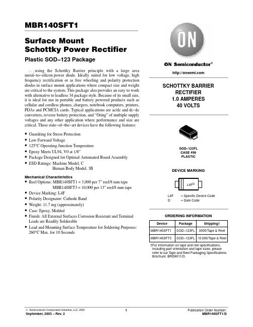
MBR140SFT1Surface MountSchottky Power Rectifier Plastic SOD−123 Packageing the Schottky Barrier principle with a large area metal−to−silicon power diode. Ideally suited for low voltage, high frequency rectification or as free wheeling and polarity protection diodes in surface mount applications where compact size and weight are critical to the system. This package also provides an easy to work with alternative to leadless 34 package style. Because of its small size, it is ideal for use in portable and battery powered products such as cellular and cordless phones, chargers, notebook computers, printers, PDAs and PCMCIA cards. Typical applications are ac/dc and dc−dc converters, reverse battery protection, and “Oring” of multiple supply voltages and any other application where performance and size are critical. These state−of−the−art devices have the following features:•Guardring for Stress Protection•Low Forward V oltage•125°C Operating Junction Temperature•Epoxy Meets UL94, V0 at 1/8″•Package Designed for Optimal Automated Board Assembly •ESD Ratings: Machine Model, CHuman Body Model, 3BMechanical Characteristics•Reel Options: MBR140SFT1 = 3,000 per 7″ reel/8 mm tapeMBR140SFT3 = 10,000 per 13″ reel/8 mm tape •Device Marking: L4F•Polarity Designator: Cathode Band•Weight: 11.7 mg (approximately)•Case: Epoxy, Molded•Finish: All External Surfaces Corrosion Resistant and TerminalLeads are Readily Solderable•Lead and Mounting Surface Temperature for Soldering Purposes: 260°C Max. for 10 SecondsDevice Package Shipping†ORDERING INFORMATIONMBR140SFT1SOD−123FLSOD−123FLCASE 498PLASTIC3000/T ape & Reel SCHOTTKY BARRIERRECTIFIER1.0 AMPERES40 VOLTSMBR140SFT3SOD−123FL10,000/Tape & ReelDEVICE MARKINGL4F= Specific Device CodeD= Date Code†For information on tape and reel specifications, including part orientation and tape sizes, please refer to our T ape and Reel Packaging Specifications Brochure, BRD8011/D.MAXIMUM RATINGSTHERMAL CHARACTERISTICS2.Mounted with 1 in. copper pad (Cu area 700 mm2). ELECTRICAL CHARACTERISTICSI F , I N S T A N T A N E O U S F O R W A R D C U R R E N T (A M P S )i F , I N S T A N T A N E O U S F O R W A R D C U R R E N T (A M P S )Figure 1. Typical Forward VoltageFigure 2. Maximum Forward Voltage0.1v F , INSTANTANEOUS FORWARD VOLTAGE (VOLTS)101.0V F , MAXIMUM INSTANTANEOUS FORWARD VOLTAGE(VOLTS)0.10.70.30.50.90.1101.00.10.70.30.50.9I R , M A X I M U M R E V E R S E C U R R E N T (A M P S )I R , R E V E R S E C U R R E N T (A M P S)Figure 3. Typical Reverse CurrentFigure 4. Maximum Reverse Current400V R , REVERSE VOLTAGE (VOLTS)V R , REVERSE VOLTAGE (VOLTS)102030400102030P F O , A V E R A G E P O W E R D I S S I P A T I O N (W A T T S )Figure 5. Current Derating I O , AVERAGE FORWARD CURRENT (AMPS)0.201.00.60.50.30.10 1.00.40.8 1.2 1.60.40.6 1.40.20.70.80.9Figure 6. Forward Power DissipationI O , A V E R A G E F O R W A R D C U RR E N T (A M P S )T L , LEAD TEMPERATURE (°C)35251.810.80.40.20754565851250.6551151.21.41.695105Figure 7. CapacitanceT J , D E R A T E D O P E R A T I N G T E M P E R A T U R E (°C )Figure 8. Typical Operating TemperatureDerating*30V R , DC REVERSE VOLTAGE (VOLTS)12565551551020254035C , C A P A C I T A N C E (p F )30V R , REVERSE VOLTAGE (VOLTS)1000100101551020254035758595105115* Reverse power dissipation and the possibility of thermal runaway must be considered when operating this device under any re-verse voltage conditions. Calculations of T J therefore must include forward and reverse power effects. The allowable operating T J may be calculated from the equation:T J = T Jmax − r(t)(Pf + Pr) wherer(t) = thermal impedance under given conditions,Pf = forward power dissipation, and Pr = reverse power dissipationThis graph displays the derated allowable T J due to reverse bias under DC conditions only and is calculated as T J = T Jmax − r(t)Pr,where r(t) = Rthja. For other power applications further calculations must be performed.r (t ), T R A N S I E N T T H E R M A L R E S I S T A N C EFigure 9. Thermal Response10000.10.00001t 1, TIME (sec)0.00010.0010.011101000.000001PACKAGE DIMENSIONSSOD−123LF CASE 498−01ISSUE ONOTES:1.DIMENSIONING AND TOLERANCING PER ANSI Y14.5M, 1982.2.CONTROLLING DIMENSION: MILLIMETER.3.DIMENSIONS A AND B DO NOT INCLUDE MOLD FLASH.4.DIMENSIONS D AND J ARE TO BE MEASURED ON FLAT SECTION OF THE LEAD: BETWEEN 0.10AND 0.25 MM FROM THE LEAD TIP.DIM MIN MAX MIN MAX INCHESMILLIMETERS A 1.50 1.800.0590.071B 2.50 2.900.0980.114C 0.90 1.000.039D 0.70 1.100.0280.043E 0.550.950.0220.037H 0.000.100.0000.004J 0.100.200.0040.008K 3.40 3.800.1340.150L0 8 °°8 °°0.035JLRECOMMENDED FOOTPRINT FOR SOD−123FLSOD−123ON Semiconductor and are registered trademarks of Semiconductor Components Industries, LLC (SCILLC). SCILLC reserves the right to make changes without further notice to any products herein. SCILLC makes no warranty, representation or guarantee regarding the suitability of its products for any particular purpose, nor does SCILLC assume any liability arising out of the application or use of any product or circuit, and specifically disclaims any and all liability, including without limitation special, consequential or incidental damages.“Typical” parameters which may be provided in SCILLC data sheets and/or specifications can and do vary in different applications and actual performance may vary over time. All operating parameters, including “Typicals” must be validated for each customer application by customer’s technical experts. SCILLC does not convey any license under its patent rights nor the rights of others. SCILLC products are not designed, intended, or authorized for use as components in systems intended for surgical implant into the body, or other applications intended to support or sustain life, or for any other application in which the failure of the SCILLC product could create a situation where personal injury or death may occur. Should Buyer purchase or use SCILLC products for any such unintended or unauthorized application, Buyer shall indemnify and hold SCILLC and its officers, employees, subsidiaries, affiliates, and distributors harmless against all claims, costs, damages, and expenses, and reasonable attorney fees arising out of, directly or indirectly, any claim of personal injury or death associated with such unintended or unauthorized use, even if such claim alleges that SCILLC was negligent regarding the design or manufacture of the part. SCILLC is an Equal Opportunity/Affirmative Action Employer. This literature is subject to all applicable copyright laws and is not for resale in any manner.PUBLICATION ORDERING INFORMATION。
硬盘MBR和GPT分区详解

硬盘MBR和GPT分区详解目前磁盘分区有两种形式:GPT分区和MBR分区。
MBR相比而言比较常见,大多数磁盘都是采用这种分区形式。
MBR分区和GPT分区的区别在于:MBR最多只支持4个主分区,GPT能够支持128个主分区。
然而GPT分区形式在重装系统需要主板的EFI支持,所以导致出现上面的这种情况。
因此解决的办法就是将分区形式转换为MBR分区形式。
但是在转换之前必须要做好数据备份,将磁盘里重要的东西全部拷出来,因为只有整个磁盘全部为空时,才能够进行转换。
传统的分区方案(称为MBR分区方案)是将分区信息保存到磁盘的第一个扇区(MBR 扇区)中的64个字节中,每个分区项占用16个字节,这16个字节中存有活动状态标志、文件系统标识、起止柱面号、磁头号、扇区号、隐含扇区数目(4个字节)、分区总扇区数目(4个字节)等内容。
由于MBR扇区只有64个字节用于分区表,所以只能记录4个分区的信息。
这就是硬盘主分区数目不能超过4个的原因。
后来为了支持更多的分区,引入了扩展分区及逻辑分区的概念。
但每个分区项仍用16个字节存储。
GPT磁盘是指使用GUID分区表的磁盘,是源自EFI标准的一种较新的磁盘分区表结构的标准。
与普遍使用的主引导记录(MBR)分区方案相比,GPT提供了更加灵活的磁盘分区机制。
MBR的全称是Master Boot Record(主引导记录),MBR早在1983年IBM PC DOS 2.0中就已经提出。
之所以叫“主引导记录”,是因为它是存在于驱动器开始部分的一个特殊的启动扇区。
这个扇区包含了已安装的操作系统的启动加载器和驱动器的逻辑分区信息。
主引导扇区是硬盘的第一扇区。
它由三个部分组成,主引导记录MBR、硬盘分区表DPT和硬盘有效标志。
在总共512字节的主引导扇区里MBR占446个字节,偏移地址0000H--0088H),它负责从活动分区中装载,并运行系统引导程序;第二部分是Partition table区(DPT分区表),占64个字节;第三部分是Magic number,占2个字节。
MBR分区表
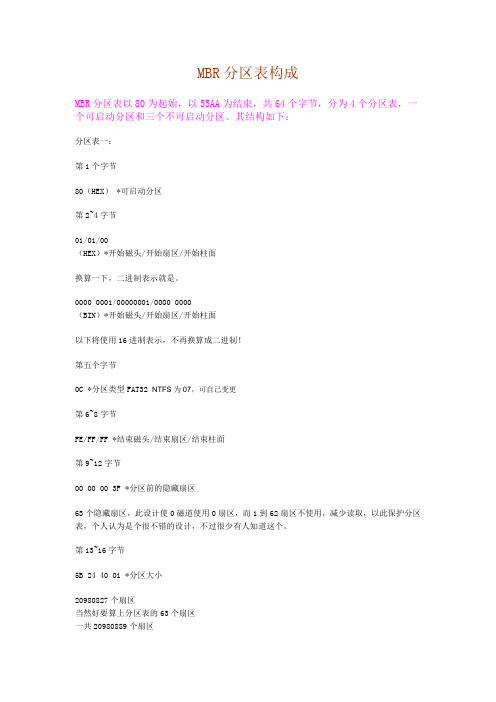
MBR分区表构成MBR分区表以80为起始,以55AA为结束,共64个字节,分为4个分区表,一个可启动分区和三个不可启动分区。
其结构如下:分区表一:第1个字节80(HEX) *可启动分区第2~4字节01/01/00(HEX)*开始磁头/开始扇区/开始柱面换算一下,二进制表示就是。
0000 0001/00000001/0000 0000(BIN)*开始磁头/开始扇区/开始柱面以下将使用16进制表示,不再换算成二进制!第五个字节0C *分区类型FAT32 NTFS为07,可自己变更第6~8字节FE/FF/FF *结束磁头/结束扇区/结束柱面第9~12字节00 00 00 3F *分区前的隐藏扇区63个隐藏扇区,此设计使0磁道使用0扇区,而1到62扇区不使用,减少读取,以此保护分区表,个人认为是个很不错的设计,不过很少有人知道这个。
第13~16字节5B 24 40 01 *分区大小20980827个扇区当然好要算上分区表的63个扇区一共20980889个扇区合10GB 公式为20980889*512/(1024^3)=10GB------------------------------------------------------我是一条分割线-----------------------------------------------分区表二:第17个字节00:不可启动分区第18~20字节开始磁头/开始扇区/开始柱面第21字节0F *分区类型为扩展分区第22~24字节结束磁头/结束扇区/结束柱面第25~28字节分区前的隐藏扇区第29~32字节分区大小分区表三,分区表四,以此类推,不再解释。
至于分区表的修改WinHex(DISKEDIT DOS下)是个不错的软件,了解了这些,就可以自己重建分区表了。
另:MBR是主分区表,误操作使MBR损坏时,DBR或者DBR备份应该没损坏,我们可以通过搜索55AA来获得DBR信息(往前找就行了),来寻找DBR从而了解更多信息(主要是分区大小和开始结束的扇区,磁头,柱头),来帮助我们重建分区表。
ThinkServer TS140 用户手册 V1.2
T品前请先阅读本手册
目录
声 明 ...................................................................................................................................................................................................................................3 商标和版权 ........................................................................................................................................................................................................................4 Safety Information(安全信息)....................................................................................................................................................................................5 第一章 产品简介 .......................................................................................................................................................................................................... 10 1.1 产品概述 ................................................................................................................................................................................................................... 10 1.2 产品特色 ................................................................................................................................................................................................................... 10
CY8CMBR3XXX_CapSense Design Guide(Chinese)
耐水性 .................................................................................................................................................................. 19
® ®
CY8CMBR3xxx CapSense 设计指南
®
文 档编号: 001-91599 版本**
2
目录
1.
简介 ................................................................................................................................................................................. 6 1.1 1.2 1.3 1.4 1.5 1.6 摘要 ....................................................................................................................................................................... 6 简介 ....................................................................................................................................................................... 6 CY8CMBR3xxx 系列特性概述 ............................................................................................................................... 7 CY8CMBR3xxx 系列的特性比较 ............................................................................................................................ 9 CY8CMBR3xxx CapSense 的系统概述 ............................................................................................................... 10 CapSense 设计流程............................................................................................................................................. 11
- 1、下载文档前请自行甄别文档内容的完整性,平台不提供额外的编辑、内容补充、找答案等附加服务。
- 2、"仅部分预览"的文档,不可在线预览部分如存在完整性等问题,可反馈申请退款(可完整预览的文档不适用该条件!)。
- 3、如文档侵犯您的权益,请联系客服反馈,我们会尽快为您处理(人工客服工作时间:9:00-18:30)。
Extremely Low Thermal ResistanceFor Surface Mount Application Low Forward VoltageMaximum RatingsOperating Temperature: -55oC to +125oC Storage Temperature: -55oC to +150oCMaximum Thermal Resistance: 200oC/W Junction to AmbientMBRX120 X220V 14V 20V MBRX130 X330V 21V 30V MBRX140 X440V 28V 40V MBRX160 X660V42V60VMaximumDCBlockingVoltage MCCCatalogNumberDeviceMarkingMaximum Recurrent Peak Reverse VoltageMaximumRMSVoltageElectrical Characteristics @ 25o C Unless Otherwise SpecifiedAverage ForwardCurrent I F(AV) 1.0A T J =90oC Peak Forward Surge CurrentI FSM20A8.3ms half sineMaximum Instantaneous Forward VoltageMBRX120MBRX130MBRX140MBRX160V F0.50V 0.55V 0.55V 0.72VI FM =1.0A T A =25o CMaximum DC Reverse Current At Rated DC Blocking Voltage I R 0.3mAT J =25oC Typical Junction CapacitanceC J 30pFMeasured at 1.0MHz,V R =4.0Vomp onents 20736 Marilla Street Chatsworth! "# $ % ! "#Micro Commercial ComponentsFeaturesLead Free Finish/RoHS Compliant (Note1)("P"Suffix designatesCompliant. See ordering information) Note: 1. High Temperature Solder Exemption Applied, see EU Directive Annex 7.• Epoxy meets UL 94 V-0 flammability rating • Moisture Sensitivity Level 1TMMicro Commercial ComponentsMBRX120 thru MBRX160Typical Forward CharacteristicsFigure 1Instantaneous Forward Current -VS Instantaneous Forward VoltageVoltsAmpsAmpsAmpsInstantaneous Forward Current -VS Instantaneous Forward VoltageVoltsInstantaneous Forward Current -VS Instantaneous Forward VoltageVoltsMBRX120MBRX130~140 MBRX160Figure 2Junction Capacitance.1.21.4210204041002001261020100pFVolts604044001000T J =25°CTa =Ta =Ta =Ta =Ta =Ta =Ta =Ta =Ta =Average Forward Rectified Current - Amperes versus Ambient Temperature -°CFigure 3Forward Derating Curve 01755075100125.2.4.6Single Phase, Half Wave60Hz Resistive or Inductive Load Amps°C150.81.01.2110041020308Figure 4Peak Forward Surge CurrentPeak Forward Surge Current - Amperes versus Number Of Cycles At 60Hz - CyclesAmpsCycles21020608040405060MBRX120 thru MBRX160www.mccsemi .comMicro Commercial Components20406080100I N S T A N T A N E O U S R E V E R S E C U R R E N T , M I L L I A M P E R E SPERCENT OF RATED PEAK REVERSEVOLTAGE, %SURFACE MOUNTTAPE DIMENSIONS AND ORIENTATION(in millimeters)8mm Ta peSOD123SURFACE MOUNTTYPETAPE SIZE BULK/TUBE 7 INCH REEL 13 INCH REEL (mm)QUANTITYQUANTITY QUANTITYSOD1238-----3000-----DIRECTION OF UNREELINGMicro Commercial ComponentsEmbossed Carrier Tape Specifications(8mm Tape)0.220mm x 12mm And Larger)Tape SizeH L J B (Max) D, F, P Constant 81.5+0.1, -0.01.75r 0.10 4.0r 0.10.600See Note 1Dimensions Tape Size E (Max)R (Min)N A (Max) KMVariable Dimensions8mm 4.2 1.0 3.5r 0.052.4 2.0r 0.05 8.0r 0.30Tape Size G4.0r 0.108.0r 0.1012.0r 0.1016.0r 0.108mmXSURFACE MOUNTTape Size R Min.8mm 25mmBending RadiusMicro Commercial ComponentsMicro Commercial Componentswww.mccsemi .comDevicePackingPart Number-TP Tape&Reel: 3Kpcs/ReelOrdering Information :***IMPORTANT NOTICE***Micro Commercial Components Corp. reserve s the right to make changes without further notice to any product herein to make corrections, modifications , enhancements , improvements , or other changes . Micro Commercial Components Corp . does not assume any liability arising out of the application or use of any product described herein; neither does it convey any license under its patent rights ,nor the rights of others . The user of products in such applications shall assume all risks of such use and will agree to hold Micro Commercial Components Corp . and all the companies whose products are represented on our website, harmless against all damages.***LIFE SUPPORT***MCC's products are not authorized for use as critical components in life support devices or systems without the express writtenapproval of Micro Commercial Components Corporation.***CUSTOMER AWARENESS***Counterfeiting of semiconductor parts is a growing problem in the industry. Micro Commercial Components (MCC) is taking strong measures to protect ourselves and our customers from the proliferation of counterfeit parts. MCC strongly encourages customers to purchase MCC parts either directly from MCC or from Authorized MCC Distributors who are listed by country on our web page cited below . Products customers buy either from MCC directly or from Authorized MCC Distributors are genuine parts, have full traceability, meet MCC's quality standards for handling and storage. MCC will not provide any warranty coverage or other assistance for parts bought from Unauthorized Sources. MCC is committed to combat this global problem and encourage our customers to do their part in stopping this practice by buying direct or from authorized distributors./分销商库存信息:MICRO-COMMERICAL-COMBRX140-TP MBRX160-TP MBRX130-TP MBRX120-TP。