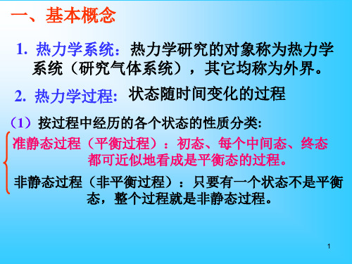
热力学研究 (2)
热力学第二定律自然界中不可逆的趋势

热力学第二定律自然界中不可逆的趋势热力学是研究能量转化和传递的科学。
其中的第二定律是一个重要的定律,它描述了自然界中不可逆的趋势。
本文将探讨热力学第二定律及其在自然界中的应用。
一、热力学第二定律的基本概念热力学第二定律是根据观察到的自然现象总结出的。
它包含两个基本概念:热量的传递只能自热量高处向自热量低处传递,而不能反向传递;熵是自然过程的不可逆度量,熵的增加是自然界中不可避免的。
第二定律还可以根据熵的观点表述为:孤立系统的熵不断增加。
二、不可逆的趋势自然界中存在许多不可逆的趋势,这正是热力学第二定律的应用范畴。
下面将介绍几个典型的不可逆过程。
1. 热量传导根据热力学第二定律,热量只能从高温物体传递到低温物体,而不能反向传递。
这是因为高温物体具有更多的热能,分子内部的热运动更为剧烈,容易传递给低温物体,而低温物体的分子运动较为缓慢,不易将热量传递给高温物体。
2. 热机效率热机是热能转化为其他形式能量的装置,例如蒸汽机、汽车引擎等。
根据热力学第二定律,热机的效率存在上限,即卡诺定理。
这是因为热机需要从高温热源中获取热量,经过部分能量转化后,将剩余的热量排放到低温环境中。
由于热量只能从高温到低温传递,因此无法完全将热源的热能转化为有用的工作,导致热机效率受限。
3. 熵的增加熵是描述系统无序度的物理量,热力学第二定律指出,系统的熵不断增加。
这意味着自然界中的各种过程都朝着更加无序的状态发展。
例如,热能从高温物体传递到低温物体时,系统的熵增加;燃烧过程中,化学能转化为热能,系统的熵增加。
熵的增加是自然界中不可逆过程的本质。
三、自然界中的应用热力学第二定律在自然界中有广泛的应用。
下面将介绍几个重要的应用领域。
1. 能源利用热力学第二定律对能源利用具有指导意义。
例如,在能源转化过程中,优先考虑高效能的方法,以减少能量的浪费。
传统汽车的能量利用效率较低,高温废热无法完全利用,因此研发高效能的新能源汽车成为趋势。
热力学的研究报告

热力学的研究报告摘要:本研究报告旨在探讨热力学的基本原理、应用和发展趋势。
首先,我们回顾了热力学的历史背景和基本概念。
接着,我们介绍了热力学的三大定律和热力学系统的分类。
随后,我们讨论了热力学在能源转换、化学反应和材料科学等领域的应用。
最后,我们展望了热力学在未来的发展方向。
1. 引言热力学是研究能量转换和能量传递的科学,它在自然科学和工程技术中扮演着重要的角色。
热力学的基本原理和定律为我们理解和解释自然界中的各种现象提供了有力的工具。
2. 热力学的基本概念和定律热力学的基本概念包括系统、热力学参数和状态函数等。
系统可以分为封闭系统、开放系统和孤立系统。
热力学的三大定律分别是热力学第一定律(能量守恒定律)、热力学第二定律(熵增定律)和热力学第三定律(绝对零度定律)。
3. 热力学系统的分类根据系统与外界的能量和物质交换情况,热力学系统可以分为开放系统、封闭系统和孤立系统。
开放系统可以与外界进行能量和物质的交换,封闭系统只能与外界进行能量交换,而孤立系统既不能与外界进行能量交换,也不能与外界进行物质交换。
4. 热力学在能源转换中的应用热力学在能源转换中起着重要的作用。
热力学分析可以帮助我们优化能源系统的设计和运行,提高能源利用效率。
例如,热力学循环(如卡诺循环)的研究可以指导我们设计高效的热力学发动机和制冷设备。
5. 热力学在化学反应中的应用热力学在化学反应中的应用可以帮助我们理解和预测反应的热效应、平衡条件和反应速率等。
热力学分析可以指导我们选择适当的反应条件,优化反应过程,提高反应产率。
热力学在化学工程和材料科学中的应用也日益重要。
6. 热力学的发展趋势随着科学技术的不断进步,热力学的研究也在不断发展。
未来的热力学研究将更加关注非平衡态热力学、微观热力学和介观热力学等领域。
同时,热力学与其他学科的交叉研究也将进一步推动热力学的发展。
结论:热力学作为一门基础科学,对于理解和解释自然界中的各种现象具有重要意义。
热力学第二定律自发变化的方向性

热力学第二定律自发变化的方向性热力学研究热量传递和能量转化的规律,其中热力学第二定律是一个基本原理,揭示了自然界中物质和能量传递的规律。
该定律提供了一个判断热现象是否自发发生的准则,即自发变化的方向性。
本文将探讨热力学第二定律自发变化的方向性以及在自然界中的应用。
热力学第二定律表达了一个重要观点:封闭系统中熵的增加是自然界中热现象发生的指示。
熵是表示物质无序程度的物理量,也可以理解为系统能量的分散程度。
热力学第二定律通过熵的概念,指出了自然界中系统趋于混乱和无序的方向性。
根据热力学第二定律,熵的增加是一个自发发生的过程。
自发变化是指不需要外界干预就会发生的变化。
在宏观尺度上,我们观察到的多数自然过程都是与熵增加相关的。
例如,热量从高温物体传递到低温物体,气体的自由扩散,液体的混合等,都是伴随熵的增加而发生的自发过程。
这些过程遵循热力学第二定律,使得系统内部的能量分布更加平均,从而增加了系统的熵。
热力学第二定律的这个观点在科学技术的各个领域都有着广泛的应用。
例如,工程领域中热机的设计和优化,需要考虑热力学第二定律对热效率的限制。
热机转化热能为机械能,包括汽车引擎、蒸汽机等。
根据热力学第二定律,热机的效率不能超过理论上的最大值,即卡诺循环的效率。
因此,工程师们需要通过改进热机的结构和工作条件,提高其效率。
另一个例子是化学反应中的自发性变化。
根据热力学第二定律,一个化学反应自发进行的条件是反应的自由能变化(ΔG)小于零。
自由能变化是化学反应在恒温、恒压下的可用能量变化。
当自由能变化为负值时,反应能够自发进行,产生化学平衡。
这个原理常常应用于工业生产中的化学反应,例如合成氨、合成尿素等。
热力学第二定律的方向性还可以解释一些自然界中的现象。
例如,热传导是热量从高温区域向低温区域传播的过程。
根据热力学第二定律,这个过程是不可逆的,因为热力学第二定律要求热量从高温区域传递到低温区域以增加系统熵。
这也解释了我们为什么感觉到热量总是从热的地方流向冷的地方。
大学物理第三章热力学第一定律第四章热力学第二定律
A1 A绝热 Q1 0 A2 A绝热 Q2 0
放热 吸热
(B)对
38
补充作业(4692)如图所示,C是固定的绝热壁, D是可动活塞,C、D将容器分成A、B两部分。 开始时A、B两室中各装入同种类的理想气体, 它们的温度T、体积V、压强P均相同,并与大 气压强相平衡。现对A、B两部分气体缓慢地 加热,当对A和B给予相等的热量Q以后,A室 中气体的温度升高度数与B室中气体的温度升 高度数之比为7:5。求:
内能:态函数,系统每个状态都对应着一定内能的数值。 功、热量:只有在状态变化过程中才有意义,状态不
变,无功、热可言。
8
五、热力学第一定律
1. 数学表式
★ 积分形式 Q E A
★ 微分形式 dQ dE dA
9
2. 热力学第一定律的物理意义
(1)外界对系统所传递的热量 Q , 一部分用于 系统对外作功,一部分使系统内能增加。
(4)内能增量: dE 2i(R适dT用于任C何V d过T程!!)
E E2 E1 CV (T2 T1 )
等容过程
Q等容 E E2 E1 CV (T2 T1 )
A等容 0
CV
iR 2
14
2. 等压过程
(1)特征: P=恒量 ,dP=0, P
参量关系: V T 恒量 (2)热一律表式:
E EA EB
E A
3
2
RTA
3 2
RTA
5 EB 2 RTB
C是导热板,因此A、B两部分气体的温度
始终相同。即:TA TB T
T A 4R
5
5
EB 2 RT 8 A
36
例4(4313)一定量的理想气体,从P-V图 上初态a经历(1)或(2)过程到达末 态b,已知a、b两态处于同一条绝热线 上(图中虚线是绝热线),问两过程中 气体吸热还是放热? (A)(1)过程吸热 (2)过程放热 (B)(1)过程放热 (2)过程吸热
热力学第二定律热量传递的方向性

热力学第二定律热量传递的方向性热力学第二定律是热力学学科中的基本定律之一,它描述了热量的传递方向性。
热力学第二定律表明,热量总是自高温区流向低温区,而不会自发地从低温区流向高温区。
本文将详细介绍热力学第二定律以及它对热量传递方向性的影响。
1. 热力学第二定律的基本原理热力学第二定律是基于实验观察而得出的,并通过数学关系进行了总结和推导。
热力学第二定律的基本原理可以概括为以下两个方面:第一,热力学第二定律排斥永动机的存在。
永动机是指能够连续不断地转化热能为机械能的理想机器。
然而,热力学第二定律指出,热量不会自发地从低温区传递到高温区,因此无法从单一热源中提取出的热量完全转化为机械能。
这一原理排除了永动机的存在。
第二,热力学第二定律引入了“熵”的概念。
熵是描述系统无序程度的物理量,可以理解为系统的混乱程度。
热力学第二定律指出,任何一个孤立系统中的熵都不会减少,而是自发地趋向于增大。
这意味着热量会不可避免地从高熵区域(低温区)流向低熵区域(高温区),进一步加强了热传递方向的确定性。
2. 热力学第二定律与热传递方向性的关系热力学第二定律对热传递方向性产生了深远的影响。
根据热力学第二定律,热量传递总是从高温区流向低温区,而不会自发地反向传递。
这一原理可以从微观和宏观两个层面进行解释。
微观层面上,物体的温度是由其微观粒子的热运动引起的。
高温意味着粒子运动更为剧烈,相邻粒子之间的能量传递更为频繁。
相反,低温意味着粒子运动较为缓慢,能量传递的频率较低。
因此,热量自然地从高温区向低温区传递。
宏观层面上,我们可以用温度差来描述热传递方向的确定性。
温度差是指不同区域之间的温度差异。
根据热力学第二定律,热传递总是自高温区向低温区进行。
这可以解释为温度差的存在使得熵增大,而熵的增大是自然趋势。
因此,热量传递方向的确定性可以从温度差的存在进行解释。
3. 热力学第二定律的应用热力学第二定律在工程和科学领域有着广泛的应用。
以下是一些热力学第二定律的应用案例:第一,热力学第二定律被应用于热机效率的研究。
热力学第二定律

热⼒学第⼆定律第⼆章热⼒学第⼆定律§2–1 引⾔(⼀) 热⼒学第⼀定律的局限性:凡是违背第⼀定律的过程⼀定不能实现,但是不违背第⼀定律的过程并不是都能⾃动实现的。
例如:1.两块不同温度的铁相接触,究竟热从哪⼀块流向哪⼀块呢?按热⼒学第⼀定律,只要⼀块铁流出的热量等于另⼀块铁吸收的热量就可以了,但实际上,热必须温度从较⾼的⼀块流向温度较低的那块,最后两块温度相等,⾄于反过来的情况,热从较冷的⼀块流向热的⼀块,永远不会⾃动发⽣。
2.对于化学反应:以上化学反应计量⽅程告诉我们,在上述条件下,反应⽣成1mol NO 2,则放热57.0KJ,若1mol NO 2分解,吸热57.0KJ ,均未违反热⼒学第⼀定律,但热⼒学第⼀定律不能告诉我们,在上述条件下的混合物中,究竟是发⽣NO 2的分解反应,还是NO 2的⽣成反应?假定是⽣成NO 2的反应能⾃动进⾏,那么进⾏到什么程度呢?这些就是过程进⾏的⽅向和限度问题,第⼀定律⽆法解决,要由第⼆定律解决。
(⼆) 热⼒学第⼆定律的研究对象及其意义:1. 研究对象:在指定条件下,过程⾃发进⾏的⽅向和限度:当条件改变后,⽅向和限度有何变化。
2. 意义:过程⾃发进⾏的⽅向和限度是⽣产和科研中所关⼼和要解决的重要问题。
例如:在化⼯及制药⽣产中,不断提出新⼯艺,或使⽤新材料,或合成新药品这⼀类的科学研究课题,有的为了综合利⽤,减少环境污染,有的为了改善劳动条件不使⽤剧毒药品,……等。
这些⽅法能否成功?也就是在指定条件下,所需要的化学反应能否⾃动进⾏?以及在什么条件下,能获得更多新产品的问题。
当然,我们可以进⾏各种实验来解决这⼀问题,但若能事先通过计算作出正确判断,就可以⼤⼤节省⼈⼒,物⼒。
理论计算认为某条件下根本不可能进⾏的反应,就不要在该条件下去进⾏实验了。
3. 研究⽅法:以⾃然界已知的⼤量事实为基础,从中抽象出它们的共性,进⽽导出⼏个新的状态函数:熵(s),亥姆霉兹⾃由能(F)和吉布斯⾃由能(G),⽤来判断过程的⽅向和限度,以达到问题的解决。
第三章 热力学第二定律
IR
WIR QIR
(Q1)IR (Q2 )IR (Q1 ) IR
T1 T2 T1
1 (Q2 )IR 1 T2
(Q1 ) IR
T1
(Q1)IR (Q2 )IR 0 用(b)中相同(T的1)环方法(,T2 )对环 任意的变温不可逆循环,也可
以用无限个微小过程代替,得到
任意不可逆循环热温商之和小于零。
BQI
A
T环
不可逆 可逆
,或
dS QI TSU
不可逆 可逆
• 若系统经绝热过程 QI 0
有
S绝 0
不可逆 ,或
可逆
dS绝 0
不可逆 可逆
• 若在隔离系统中发生的过程 QI 0
不可逆
S隔 0 可逆 ,或
不可逆
dS隔 0 可逆
此二式就是熵增加原理的数学表达式。它表示:在绝
热或隔离系统中进行不可逆过程(实际可发生的过
低温物体(T(不2)可逆)
由上分析看见:无论是功→热的转化,还是 传热过程都 有明确的方向。这些实际发生的过 程都不能简单逆转,其共性——都是不可逆的
9
3.2 熵,熵增原理···················
1. 卡诺定理
(i)工作于两个一定温度间的所有卡诺循环都有相同 的
效率
R
T1 T2 T1
若V1 V2
S
CV
为常数
,m
nCV ,m
ln
T2
T1
由此二式可知,当T2>T1,ΔS>0,即定压(或定容) 下,S高温>S低温。
21
(3)系统经绝热可逆过程 (QR )S 0 , (QR )S 0
S
QR
T
0
热力学的研究进展

热力学的研究进展热力学是研究能量转化和热力学性质的一门科学。
自18世纪以来,热力学一直是自然科学中的重要领域,并在工程、物理、化学等各个学科中发挥着重要的作用。
随着科学技术的不断发展,热力学的研究也取得了许多进展。
本文将介绍热力学研究中的一些重要领域和近年来的一些新进展。
一、热力学的基本原理热力学的基本原理可以通过热力学第一定律和第二定律来描述。
热力学第一定律是能量守恒定律,表明能量是可以转化的,能量的转化可以改变形式但不会增减。
热力学第二定律则涉及到熵的概念,它描述了热力学过程的不可逆性和自发性。
二、热力学在工程中的应用热力学在工程领域中的应用非常广泛。
例如,热力学常被用来分析和设计热能转换系统,如汽车发动机、发电厂和制冷设备等。
热力学还被广泛应用于能源利用和环境保护领域,例如太阳能和风能的利用以及温室气体的控制等。
三、非平衡态热力学的研究近年来,非平衡态热力学成为热力学研究中的一个重要领域。
传统的平衡态热力学只适用于稳定系统,而非平衡态热力学研究的是诸如输运过程、非平衡相变等动态过程。
通过引入非平衡态热力学,我们可以更好地理解和描述一些复杂系统中的能量转化和热力学特性。
四、微观热力学的发展微观热力学是研究热力学现象的微观本质和微观机制的学科。
随着计算机技术的发展和数值模拟方法的进步,微观热力学的发展取得了显著的进展。
通过分子动力学模拟和蒙特卡洛模拟等方法,我们可以更加准确地研究和描述系统的微观行为,为热力学研究提供了新的手段和视角。
五、热力学与信息理论的交叉研究热力学与信息理论的交叉研究是近年来热力学研究的一个新兴领域。
信息热力学理论的提出将热力学和信息论有机地结合在一起,揭示了能量转化和信息传递之间的关系。
这一领域的发展为我们更深入地理解热力学现象和信息传递提供了新的思路和方法。
总结起来,热力学作为一门重要的科学领域,不断取得了新的进展和突破。
从基本原理到应用领域的扩展,从非平衡态热力学到微观热力学的研究,以及与信息理论的交叉研究等,这些都为我们更深入地理解能量转化和热力学性质提供了新的视角和方法。
- 1、下载文档前请自行甄别文档内容的完整性,平台不提供额外的编辑、内容补充、找答案等附加服务。
- 2、"仅部分预览"的文档,不可在线预览部分如存在完整性等问题,可反馈申请退款(可完整预览的文档不适用该条件!)。
- 3、如文档侵犯您的权益,请联系客服反馈,我们会尽快为您处理(人工客服工作时间:9:00-18:30)。
A durable ruthenium catalyst for the NaBH 4hydrolysisY.C.Zou,Y.M.Huang *,X.Li,H.L.LiuKey Laboratory of Specially Functional Polymeric Materials and Related Technology of the Ministry of Education,Department of Chemistry,East China University of Science and Technology,Shanghai 200237,PR Chinaa r t i c l e i n f oArticle history:Received 22September 2010Received in revised form 4January 2011Accepted 7January 2011Available online 2February 2011Keywords:Hydrogen generation Sodium borohydride Supported Ru catalyst Durability of catalysta b s t r a c tRu-active carbon (Ru/C)catalysts are prepared by impregnation reduction method for hydrogen generation via hydrolysis of alkaline sodium borohydride (NaBH 4)solution.The corresponding activity and durability of the prepared catalysts are tested in an immobile bed reactor.The variation of hydrogen generation rate with the increasing of flux and concentration of NaBH 4solution is measured.The durability of the catalysts prepared under various reductive pH values and reductants is tested by using different concentra-tions of NaBH 4solution (10&15wt%).It is found that the durability of catalyst in 15wt%NaBH 4solution is longer than that in 10wt%NaBH 4solution.The deactivation of Ru/C catalysts is considered as the comprehensive effect of three factors:the loss of Ru,the deposition of byproducts on the catalyst surface and the aggregation of Ru particles.Copyright ª2011,Hydrogen Energy Publications,LLC.Published by Elsevier Ltd.All rightsreserved.1.IntroductionPeople are very interested in hydrogen because it is considered to be an ideal power source in the future.It can provide both heat energy through combustion and electricity via fuel cells.Fuel cell is an energy-conversion device which can directly convert the chemical energy into electric energy at high effi-ciency [1].Among various fuel cells,the proton exchange membrane fuel cell (PEMFC)is considered as the best choice for vehicle,portable power and small-scale stationary appli-cations due to its high power density,low operating temper-ature,high efficiency,fast response,low system weight as well as zero emission [2].However,the inconvenience of the storage and transportation of the fuel of PEMFC,hydrogen,hinders the application of PEMFC dramatically.Chemical hydrides are widely used in the field of fuel cells.The unique properties of chemical hydrides have attracted increasing interest and are being recognized for their poten-tial applications in hydrogen pared with othertechnologies including gas compression or liquefaction,solid-state materials and so on,these hydrides can store hydrogen at much milder ambient,room temperature and relatively low pressure [3,4].Among these hydrides,NaBH 4has become the most prominent one of its high stability,nonflammability,nontoxicity in nature and high hydrogen content [5e 7].Cento et al.[8]studied the hydrolysis of sodium borohydride (SBH)to produce hydrogen at various tempera-tures.Wee et al.[9]introduced some research achievements on the use of H 2generated from the NaBH 4hydrolysis for PEMFCs.The hydrolysis of NaBH 4in the presence of a suitable catalyst could be carried out according to the reaction (1)[10].Various catalysts have been developed for the catalytic hydrolysis of NaBH 4solution to generate pure hydrogen,such as Pt-based catalyst [11],Ru-based catalyst [12e 16],Pt e Ru alloy catalyst [17],Pd-based catalyst [18],Co-based catalyst [19,20],Ni-based catalyst [21],etc.The studies proved that the catalysts containing Ru showed significant advantages in liberating H 2from NaBH 4.*Corresponding author .Tel.:þ862164250924;fax:þ862164252921.E-mail address:huangym@ (Y.M.Huang).A v a i l a b l e a t w w w.s c i e n c e d i r e c t.c o mj o u r n a l h o m e p a g e :w w w.e l s e v i e r.c o m /l o c a t e /h ei n t e r n a t i o n a l j o u r n a l o f h y d r o g e n e n e r g y 36(2011)4315e 43220360-3199/$e see front matter Copyright ª2011,Hydrogen Energy Publications,LLC.Published by Elsevier Ltd.All rights reserved.doi:10.1016/j.ijhydene.2011.01.027NaBH 4þðx þ2ÞH 2O !CatalystNaBO 2$x H 2O þ4H 2[(1)Amendola et al.[22]investigated ruthenium based catalyst supported on ion exchange resin beads for hydrogen genera-tion from hydrolysis of NaBH 4.Shang et al.[23]studied the kinetic of NaBH 4hydrolysis with carbon-supported Ru and found that the hydrolysis rate of NaBH 4with Ru catalyst was the zero order with respect to the concentration of NaBH 4when water was sufficient.Hung et al.[24]hold the view that the reaction order with the NaBH 4concentration depends on the temperature,which is a zero order at the low temperature and the first order at the high temperature.Shang and Chen [25]found that the hydrogen generation rate of concentrated alkaline NaBH 4solutions was affected not only by NaBH 4concentration,NaOH concentration but also by the byproduct (sodium metaborate).So far,the study of catalysts for hydrolysis of NaBH 4has been focusing on intermittent reaction performance,while the durability and the deactivation mechanism of catalyst in continuous and semi-continuous reaction process have been rarely investigated.In this work,supported Ru catalysts were prepared with different reductants and reductive pHs firstly.Both the durability of the catalysts and the hydrogen gener-ation rate were tested by pumping the different concentra-tions of NaBH 4solution (10&15wt%)into an immobile bed reactor.Furthermore,the deactivation mechanism of Ru/C catalysts is discussed via EDS,XRD and TEM.2.Material and methods2.1.Preparation of catalystThe Ru/C catalysts were prepared by impregnation method in which the analytical reagent grade ruthenium trichloride RuCl 3was used as the metal precursor and the spherical active carbon as the carrier.Synthesis procedure of Ru/C catalyst was summarized as below.40ml 0.06mol/L RuCl 3solution was prepared and its pH value was adjusted to 3.0.A weighed amount of the spherical active carbon was added to the above solution and dipped in the solution for 24h at the room temperature.It could be observed that the color of this solu-tion turned from red-brown to colorless.Subsequently,the 5wt%NaOH was used to adjust pH value of the mixture to 10e 11,and NaBH 4or HCHO was dropwise added to the mixture as the reductant.After that,the catalyst was filtered and washed repeatedly with deionized water until no Cl Àcould be detected.Finally,the sample was dried at 60 C for 6h in a vacuum system and then the Ru/C catalyst was obtained.The above method was applied to prepare three cata-lysts with different reductive pH and reductants,which were named as Ru/C e NaBH 4-pH10,Ru/C e HCHO-pH10and Ru/C e HCHO-pH11respectively.The surface area of the carrier was determined by BET (Micrometrics ASAP 2010)and the pore diameter distribution was obtained by BJH.The phases and lattice parameters of the catalysts were characterized by X-ray diffraction (XRD)with Cu K a radiation.The scan range was from 10 to 90 ,and the scan rate was 4 /min in step of 0.02 .The accelerating voltage and current were 40kV and 100mA.The surface morphologyof the catalysts was observed by a transmission electron microscope (TEM,JEM-2010).The energy dispersive spectrum (EDS)was used to analyze the atomic composition of the catalysts.2.2.Durability determination of catalystThe catalytic durability of the catalysts in the hydrolysis of NaBH 4was determined by measuring the conversion of sodium borohydride.Fig.1shows the experimental installation.NaBH 4solution was placed in a plastic tank and pumped into the reactor by a feed pump,and the rate of hydrogen generation was controlled by adjusting the flux of reaction solution.There was a gas e liquid separator equipped with the reactor,the hydrogen produced from the hydrolysis of sodium borohydride overflowed from the upper part of the gas e liquid separator,while the solution containing the sodium metabo-rate and unreacted sodium borohydride flowed into the effluent liquid tank.The load of catalyst in the reactor was about 2g.The experimental procedure was summarized as below.The feed pump was started at 9:00am and the reaction was stopped at 9:00pm everyday,and the part of effluent liquid was collected at a given interval,then the NaBH 4concentration in the collected liquid was determined by the indirect iodimetry.Correspondingly,the conversion of NaBH 4was calculated by comparing with the concentration of NaBH 4before reaction.The initial conversion of NaBH 4solution was about 98%.The reaction didn’t stop until the conversion of NaBH 4solution decrease to 50%(the time is named as active half-life of catalyst).The indirect iodimetry was performed as following steps:the excess KIO 3solution was added into quantitative NaBH 4solution and the redox reactionoccurred.Fig.1e Experimental installation of catalyst durability:1.reactor;2.gas e liquid separator;3.container for NaBH 4;4.feed pump;5.effluent liquid tank.i n t e r n a t i o n a l j o u r n a l o f h y d r o g e n e n e r g y 36(2011)4315e 432243163NaBH4þ4KIO3/3NaBO2þ4KIþ6H2O(2)The solution was acidified with H2SO4and then the remaining KIO3reacted with excess KI,which generated I2.KIO3þ5KIþ3H2SO4/3I2þ3K2SO4þ3H2O(3)At last,Na2S2O3standard solution was used to titrate the amount of I2and the starch as the indicator.I2þ2Na2S2O3/2NaIþNa2S4O6(4)Specific experimental steps were described as follows.2.00ml NaBH4solution was taken in50ml volumetricflask with the pipette and then diluted to the scale with1mol/L NaOH solution.5.00ml sample solution was moved to the iodineflask and then20.00ml standard potassium iodate solution was added.After they mixed fully,appropriate KI solution and sulfuric acid solution were added.At last, Na2S2O3standard solution was used to titrate the solution and the starch was added to the solution as the indicator. Continue to drip standard Na2S2O3solution until the color of the solution turned from dark blue to colorless.The concen-tration of sodium borohydride can be determined by the following formula:C NaBH4¼ðV1C1ÀV2C2=6ÞÂ154(5)C1d the concentration of KIO3standard solution,mol/L.C2d the concentration of Na2S2O3standard solution,mol/L. V1d the volume of KIO3standard solution,ml.V2d the volume of Na2S2O3standard solution,ml.The durability of three catalysts prepared in this work was tested in10wt%NaBH4solution,and then the effects of two preparation conditions on the durability of catalysts were investigated.The durability of catalysts in15wt%NaBH4 solution was also tested in order to investigate the effect of NaBH4concentration.2.3.Generation of hydrogenAccording to the results of durability determination,the catalyst which had the longest durability was selected to test the hydrogen generation rate by hydrolysis of NaBH4.Fig.2shows the experimental installation which consists of feed pump,reactor, gas e liquid separator and the alkali gas absorber.The alkali gas absorber is connected to the top outlet of the gas e liquid sepa-rator to absorb the alkali mist produced from the hydrolysis of NaBH4solution.The hydrogen generation rate was measured with a stopwatch and a recording rotameter at differentflow rates of NaBH4and different NaBH4concentrations.The NaBH4flow rate was0.5,1.0,1.5and2.0ml/min,while the concentration of NaBH4was10wt%,15wt%and20wt%,respectively.3.Results and discussion3.1.Characterization of Ru/C catalystsAdsorption e desorption isotherm of the carrier is displayed in Fig.3.It presents that the branches of adsorption and desorption are almost superposition,and the hysteresis loop is of a small area which elucidates that the support has both micro-pore and mid-pore.Pore diameter distribution of the support is shown in Fig.4,where we can see that pore diam-eter of the support is mainly about2nm which is consistent with the results of adsorption experiment.The specific surface area of the carrier measured by N2adsorption is 976m2/g.Fig.5(2e4)displays the XRD patterns of Ru/C e NaBH4-pH10, Ru/C e HCHO-pH10and Ru/C e HCHO-pH11catalysts,respec-tively.The diffraction peak at2q¼20e30 is that of carbon and the diffraction peaks around44 and78 are characteristic ones of Ru,which indicates that Ru is loaded on the carrier successfully.According to Scherrer formula,the catalyst particle size calculated from three curves is4.27,4.60and5.47nm,respectively.The curve1is the XRD pattern of Ru/C e NaBH4-pH10catalyst reacted in10wt%NaBH4solution for 216h,and the size of it is4.78nm which is bigger than that of the original one(4.27nm),which elucidates that the metal particles on catalysts have agglomerated during the course ofreaction. Fig.2e Experimental installation of testing hydrogen generation rate:1.reactor;2.alkali gas absorber;3. container for NaBH4;4.feed pump;5.gas e liquidseparator.Fig.3e Nitrogen adsorption e desorption isotherms of support.i n t e r n a t i o n a l j o u r n a l o f h y d r o g e n e n e r g y36(2011)4315e43224317Fig.6presents the quantitative chemical composition of Ru/C catalysts demonstrated by EDS.Fig.6(a),(c)and (e)represent the catalysts before reaction,while Fig.6(b),(d)and (f)represent the catalysts after reaction in 10wt%NaBH paring Fig.6(a)with Fig.6(b)about Ru/C e NaBH 4-pH10catalyst,we can see that the content of Ru in the catalyst decreases from 0.89at%to 0.67at%before and after reaction,which reveals that the loading of the metal ruthenium decreases during the reaction.Furthermore,the Na atoms appear in Fig.6(b)but not in Fig.6(a),which indicates that the reaction byproducts or the reactant NaBH 4deposited on the catalyst surface.The presence of sediment will cover the ac-tive positions of the catalysts,which is one of the reasons for deactivation of catalysts.Fig.6(c)and Fig.6(d)provide the chemical composition of Ru/C e HCHO-pH10catalyst before and after reaction.The loading of Ru in the catalyst decreases from 1.79at%to 0.89at%during the reaction.The amount of loaded Ru on Ru/C e HCHO-pH10catalysts is more than that on Ru/C e NaBH 4-pH10catalysts,but the load intensity between the metal particles and the carrier is weaker,which leads to much more loss of Ru during the reaction.Similarly,the Na atoms can be observed in Fig.6(d)but not in Fig.6(c).Fig.6(e)and (f)provide the difference of Ru/C e HCHO-pH11catalystbefore and after reaction.The loading of Ru is 1.87at%and 0.75at%,respectively,which are close to the loading of Ru in Ru/C e HCHO-pH10catalyst.From the comparison among (a),(c)and (e),it can be found that the loading of Ru on catalysts prepared with the reductant HCHO is more than that with the reductant NaBH 4.However,the effect of pH on the loading of Ru is less obvious.Fig.7presents TEM micrographs of Ru/C e NaBH 4-pH10catalyst.Fig.7(a)displays that the original catalyst is covered by uniform small metal particles.Fig.7(b)shows the morphology of catalyst reacted in 10wt%NaBH 4solution for 216h.From Fig.7,it can be seen that the small metal particles on catalysts tend to aggregate together,which leads to the increase of particle size and the decrease of active specific surface area.The same conclusion has been drawn in Fig.5that the Ru particle size in Ru/C e NaBH 4-pH10catalyst changed from 4.27nm to 4.78nm before and after reaction.It is obvious that the catalyst particles with higher active specific surface area are less stable in thermodynamics and have lower melting point.The hydrolysis of sodium borohydride is exothermic reaction.The temperature of 10wt%NaBH 4solution hydrolyzed with 2g Ru/C e NaBH 4-pH10catalyst is about 75 C,while the temperature inside the catalyst is likely to be higher.The large amount of heat released in NaBH 4hydrolysis promotes the fusion of these small particles.The melting particles then move along the carrier surface,merge mutually and finally lead to the formation of stable macro-particle.This is the possible reason for the recognizable reduction of catalytic activity in the present study.3.2.Durability of Ru/C catalysts 3.2.1.Effect of reductive pHFig.8illustrates the durability of catalysts prepared under the condition of different pH and HCHO as the reductant in 10wt%NaBH 4solution,in which the content of NaOH is 4wt%.As shown in Fig.8,the initial conversion rate of the NaBH 4solution of Ru/C e HCHO-pH10is higher than that of Ru/C e HCHO-pH11.As the reaction proceeds,the activities of the two catalysts show a marked decline.After 132h reaction,the conversion rate of NaBH 4of Ru/C e HCHO-pH11decreases to 51.89%and the catalyst nearly reaches its active paratively,the active half-life of Ru/C e HCHO-pH10is prolonged to 192h.The difference of active half-life between two catalysts should be attributed to the different reductive pH values which have important influence on the metal particle size.It can be confirmed by Fig.5that the Ru particle size of Ru/C e HCHO-pH10catalyst calculated via XRD is 4.60nm and that of Ru/C e HCHO-pH11catalyst is 5.47nm.The catalysts with small particle size will have big active specific surface area,which makes the catalysts have high activity.The above results suggest that the catalyst prepared under the pH value of 10is more suitable to catalyze the hydrolysis of NaBH 4solution.3.2.2.Effect of reductantsFig.9depicts the durability of catalysts prepared with different reductants in 10wt%NaBH 4solution,in which the content of NaOH is 4wt%.It is found that the initial conver-sion rate of 10wt%NaBH 4of Ru/C e HCHO-pH10catalyst is higher than that of Ru/C e NaBH 4-pH10catalyst.Reasonably,Fig.4e Pore diameter distribution ofsupport.Fig.5e XRD patterns of catalysts.i n t e r n a t i o n a l j o u r n a l o f h y d r o g e n e n e r g y 36(2011)4315e 43224318the loading of Ru in Ru/C e HCHO-pH10is much more than that in Ru/C e NaBH 4-pH10from Fig.6(a)and (c).However,with the reaction going on,the deactivation rate of Ru/C e NaBH 4-pH10catalyst becomes slower and slower.The conversion rates of two catalysts reach the same value after ter,the conversion rate of NaBH 4of Ru/C e NaBH 4-pH10catalyst becomes higher than that of Ru/C e HCHO-pH10catalyst.The active half-life of Ru/C e NaBH 4-pH10catalyst andRu/C e HCHO-pH10catalyst are 216h and 192h,respectively.The above results are consistent with the analysis of EDS in Fig.6in which the catalyst Ru/C e HCHO-pH10loads more Ru but with a faster loss of it during the course of reaction.3.2.3.Effect of NaBH 4concentrationRu/C e NaBH 4-pH10catalyst and Ru/C e HCHO-pH10catalyst were chosen to test the durability in 15wt%NaBH 4in ordertoFig.6e EDS spectra of catalysts:(a)Ru/C e NaBH 4-pH10before reaction;(b)Ru/C e NaBH 4-pH10after reaction;(c)Ru/C e HCHO-pH10before reaction;(d)Ru/C e HCHO-pH10after reaction;(e)Ru/C e HCHO-pH11before reaction;(f)Ru/C e HCHO-pH11after reaction.i n t e r n a t i o n a l j o u r n a l o f h y d r o g e n e n e r g y 36(2011)4315e 43224319demonstrate the effect of NaBH 4concentration on the dura-bility of the catalysts.The content of NaOH in 15wt%NaBH 4was also 4wt%.Fig.10reflects the effect of NaBH 4concentration on the durability of catalysts.As shown in Fig.10(a),both 10wt%andFig.7e TEM of catalysts:(a)Ru/C e NaBH 4-pH10before reaction;(b)Ru/C e NaBH 4-pH10afterreaction.Fig.8e Durability of catalysts prepared under different pH in 10wt%NaBH 4.Fig.9e Durability of catalysts prepared with different reductant in 10wt%NaBH 4.Fig.10e Durability of catalysts in different concentration of NaBH 4solution:(a)Ru/C e NaBH 4-pH10in 10wt%and 15wt %NaBH 4solution;(b)Ru/C e HCHO-pH10in 10wt%and 15wt%NaBH 4solution.i n t e r n a t i o n a l j o u r n a l o f h y d r o g e n e n e r g y 36(2011)4315e 4322432015wt%NaBH 4solution catalyzed with Ru/C e NaBH 4-pH10catalyst have the high initial conversion of 96%.As the reaction proceeds,the activity of catalyst in 10wt%NaBH 4solution decreases obviously,while that hardly changes at the first 150hin 15wt%NaBH 4solution.After 156h,the conversion rate of 10wt%NaBH 4is 74.85%,but that of 15wt%NaBH 4is still as high as 95.38%under the action of catalyst.When the reaction is going on for 216h,the conversion rate of 10wt%NaBH 4reduces to 50.31%and the catalyst reaches its half-life.At the same time,the conversion rate of 15wt%NaBH 4is 92.20%,which reflects that the durability of the catalyst in 15wt%NaBH 4is much longer than that in 10wt%NaBH 4.Fig.10(b)provides the durability of Ru/C e HCHO-pH10catalyst in 10wt%and 15wt%NaBH 4solution,which shows the similar result.The above results are contrary to our expectations,which may be attributed to the cooperation of the viscosity of hydro-lysis product and the formation of crystallite.As reported,the phase composition after NaBH 4hydrolysis reaction was different when the concentration of NaBH 4was between 0e 12.3wt%and 12.3e 25.9wt%[26].On the one hand,the hydrolysis product of the latter begins to form microcrystal of NaB(OH)4$2H 2O that may enhance the viscosity of the hydrolysis product macroscopically.The viscosity of the initial hydrolysis product for 10wt%NaBH 4and 15wt%NaBH 4are 4.68and 10.42Pa $s,respectively.As the same concentration of NaBH 4solution,the viscosity of the hydrolysis product at initial reaction stages is apparently larger than that at latter reaction stages.On the other hand,crystallite will deposit on the surface of catalyst and grow up,which covers the active center of catalyst and leads to the deactivation of catalyst.We believe that the increase of viscosity would prevent the crystallite from subsiding,which benefits the maintenance of the catalyst activity.Therefore,the conversion rate of NaBH 4at the initial reaction stages declines slowly and the recession of it speeds up gradually along with the reaction time.However,it is worth mentioning that the depo-sition of crystallite will dominate the deactivation of catalysts when the concentration of NaBH 4is high enough.3.3.Hydrogen generationFig.11shows the hydrogen generation rate in different concentrations of NaBH 4solution with Ru/C e NaBH 4-pH10catalyst.It is shown that the variation of the concentration and flow rate of NaBH 4solution hardly affects the response time of the paring the curves of each figure separately,we can easily find that the hydrogen generation rate increases in proportion to the flow rate of NaBH paring the curves at the same flow rate in three figures,such as the flow rate at 0.5ml/min,we find that the hydrogen generation rate of 10wt%NaBH 4is about 55ml/min/g,while that of 15wt%and 20wt%are about 85ml/min/g and 110ml/min/g,respectively.Obviously,the hydrogen generation rate is proportional to the concentration of NaBH 4at the same flux,which indicates that the catalyst has the high sensitivity and satisfactory perfor-mance.The hydrogen generation rate can reach 376ml/min/g with 20wt%NaBH 4when the flow rate is 2.0ml/min.4.ConclusionsIn this work,three catalysts,Ru/C e NaBH 4-pH10,Ru/C e HCHO-pH10and Ru/C e HCHO-pH11,were prepared under the condition of different reductants and different reductive pH value for hydrogen generation by hydrolysis of NaBH4Fig.11e Hydrogen generation rate in differentconcentration of NaBH 4with Ru/C e NaBH 4-pH10:(a)Hydrogen generation rate in 10wt%NaBH 4;(b)Hydrogen generation rate in 15wt%NaBH 4;(c)Hydrogen generation rate in 20wt%NaBH 4.i n t e r n a t i o n a l j o u r n a l o f h y d r o g e n e n e r g y 36(2011)4315e 43224321solution.It is found that both the reductant and the reductive pH greatly affect the performance of the catalysts.The dura-bility of Ru/C e NaBH4-pH10catalyst in10wt%NaBH4solution is about216h,which is longer than that of other two catalysts. Furthermore,the durability of catalyst in15wt%NaBH4 solution is longer than that in10wt%NaBH4solution.When Ru/C e NaBH4-pH10catalyst reacts in15wt%NaBH4solution for264h,the conversion of15wt%NaBH4is still78.40%.The hydrogen generation rate was carefully tested.When the Ru/C e NaBH4-pH10catalyst with0.89at%Ru is applied to the hydrolysis of20wt%NaBH4solution,the hydrogen generation rate can reach376ml/min/g with theflux of2.0ml/min.According to the durability of catalysts as well as other characterization results,the deactivation mechanism of Ru/C catalysts is summarized as below:loss of the active compo-nent Ru,deposition of byproducts on the catalyst surface and agglomeration of Ru particles.AcknowledgmentsThis work was supported by the Fundamental Research Funds for the Central Universities(WK1013001)and the Program for Changjiang Scholars and Innovative Research Team in University of China(gs2)(Grant IRT0721).r e f e r e n c e s[1]Krishnan P,Hsueh KL,Yim SD.Catalysts for the hydrolysis ofaqueous borohydride solutions to produce hydrogen for PEM fuel cells.Appl Catal B Environ2007;77:206e14.[2]Patel N,Fernandes R,Miotello A.Hydrogen generation byhydrolysis of NaBH4with efficient Co e P e B catalyst:a kinetic study.J Power Sources2009;188:411e20.[3]Kong VCY,Kirk DW,Foulkes FR,Hinatsu JT.Development ofhydrogen storage for fuel cell generators II:utilization ofcalcium hydride and lithium hydride.Int J Hydrogen Energy 2003;28:205e14.[4]Sifer N,Gardner K.An analysis of hydrogen production fromammonia hydride hydrogen generators for use in militaryfuel cell environments.J Power Sources2004;132:135e8. [5]Huang Y,Wang Y,Zhao R,Shen PK,Wei Z.Accuratelymeasuring the hydrogen generation rate for hydrolysis ofsodium borohydride on multiwalled carbon nanotubes/Co e B catalysts.Int J Hydrogen Energy2008;33:7110e5.[6]Demirci UB,Akdim O,Miele P.Aluminum chloride foraccelerating hydrogen generation from sodium borohydride.J Power Sources2009;192:310e5.[7]Pinto AMFR,Falca˜o DS,Silva RA,Rangel CM.Hydrogengeneration and storage from hydrolysis of sodium borohydride in batch reactors.Int J Hydrogen Energy2006;31:1341e7. [8]Cento C,Gislon P,Prosini PP.Hydrogen generation byhydrolysis of NaBH4.Int J Hydrogen Energy2009;34:4551e4.[9]Wee JH,Lee KY,Kim SH.Sodium borohydride as thehydrogen supplier for proton exchange membrane fuel cell systems.Fuel Process Technol2006;87:811e9.[10]Akdim O,Demirci UB,Miele P.Highly efficient acid-treatedcobalt catalyst for hydrogen generation from NaBH4hydrolysis.Int J Hydrogen Energy2009;34:4780e7.[11]Bai Y,Wu C,Wu F,Yi B.Carbon-supported platinumcatalysts for on-site hydrogen generation from NaBH4solution.Mater Lett2006;60:2236e9.[12]Chen CW,Chen CY,Huang YH.Method of preparingRu-immobilized polymer-supported catalyst for hydrogengeneration from NaBH4solution.Int J Hydrogen Energy2009;34:2164e73.[13]Hsueh CL,Chen CY,Ku JR,Tsai SF,Hsu YY,Tsau F,et al.Simple and fast fabrication of polymer template-Rucomposite as a catalyst for hydrogen generation fromalkaline NaBH4solution.J Power Sources2008;177:485e92.[14]Masjedi M,Demiralp T,o¨zkar S.Testing catalytic activity ofruthenium(III)acetylacetonate in the presence oftrialkylphosphite or trialkylphosphine in hydrogengeneration from the hydrolysis of sodium borohydride.J Mol Catal A:Chem2009;310:59e63.[15]Amendola SC,Sharp-Goldman SL,Janjua MS,Kelly MT,Petillo PJ,Binder M.An ultrasafe hydrogen generator:aqueous, alkaline borohydride solutions and Ru catalyst.J PowerSources2000;85:186e9.[16]Liang Y,Dai HB,Ma LP,Wang P,Cheng HM.Hydrogengeneration from sodium borohydride solution usinga ruthenium supported on graphite catalyst.Int J HydrogenEnergy2010;35:3023e8.[17]Krishnan P,Yang TH,Lee WY,Kim CS.PtRu-LiCoO2e anefficient catalyst for hydrogen generation from sodiumborohydride solutions.J Power Sources2005;143:17e23. [18]Patel N,Patton B,Zanchetta C,Fernandes R,Guella G,Kale A,et al.Pd e C powder and thinfilm catalysts for hydrogenproduction by hydrolysis of sodium borohydride.Int JHydrogen Energy2008;33:287e92.[19]Kim DR,Cho KW,Choi YI,Park CJ.Fabrication of porousCo e Ni e P catalysts by electrodeposition and their catalytic characteristics for the generation of hydrogen from analkaline NaBH4solution.Int J Hydrogen Energy2009;34:2622e30.[20]Garron A,Swierczynski D,Bennici S,Auroux A.New insightsinto the mechanism of H2generation through NaBH4hydrolysis on Co-based nanocatalysts studied by differential reaction calorimetry.Int J Hydrogen Energy2009;34:1185e99.[21]Kim JH,Lee H,Han SC,Kim HS,Song MS,Lee JY.Productionof hydrogen from sodium borohydride in alkaline solution: development of catalyst with high performance.Int JHydrogen Energy2004;29:263e7.[22]Amendola SC,Sharp-Goldman SL,Janjua MS,Spencer NC,Kelly MT,Petillo PJ,et al.A safe,portable,hydrogen gasgenerator using aqueous borohydride solution and Rucatalyst.Int J Hydrogen Energy2000;25:969e75.[23]Shang Y,Chen R,Jiang G.Kinetic study of NaBH4hydrolysisover carbon-supported ruthenium.Int J Hydrogen Energy2008;33:6719e26.[24]Hung AJ,Tsai SF,Hsu YY,Ku JR,Chen YH,Yu CC.Kinetics ofsodium borohydride hydrolysis reaction for hydrogengeneration.Int J Hydrogen Energy2008;33:6205e15.[25]Shang Y,Chen R.Semiempirical hydrogen model usingconcentrated sodium borohydride solution.Energy Fuels2006;20(5):2149e54.[26]Liu BH,Li ZP.A review:hydrogen generation fromborohydride hydrolysis reaction.J Power Sources2009;187: 527e34.i n t e r n a t i o n a l j o u r n a l o f h y d r o g e n e n e r g y36(2011)4315e4322 4322。