槽式消化机自动控制原理
自动控制原理
《自动控制原理》课程设计摘要本文介绍了基本的水位控制系统,在水位控制系统中,水槽是常见的水位控制系统的被控对象。
所以又主要针对了双容水槽的数学模型进行了基本参数设定及求其传递函数,微分方程,校正与仿真。
关键词:校正,水位控制,根轨迹法设计目的通过课程设计,在掌握自动控制理论基本原理、一般电学系统自动控制方法的基础上,用MATLAB 实现系统的仿真与调试。
要求根据所学控制理论知识,用根轨迹法进行人工设计校正装置,初步设计出校正装置传递函数形式及参数。
要求在MATLAB 下,用simulink 进行状态仿真,在计算机上对人工设计系统进行仿真调试,使其满足技术要求;确定校正装置的电路形式及电路参数;完成设计报告。
题目设计要求饲养场水槽水位控制系统校正装置设计已知饲养场水槽水位控制为单位反馈控制系统,其开环传递函数为)2()(+=s s K s G K ,用根轨迹法设计一个超前校正装置,使之满足性能指标: %20≤P M ,s t s 1≤。
水位控制系统在工农业生产以及日常生活应用中,常常会需要对容器中的液位(水位)进行自动控制。
比如自动控制水箱、水池、水槽、锅炉等容器中的蓄水量,生活中抽水马桶的自动补水控制、自动电热水器、电开水机的自动进水控制等。
虽然各种水位控制的技术要求不同,精度不同,但基本的控制原理都可以归纳为一般的反馈控制方式,如下图所示,它们的主要区别在于检测液位的方式、反馈形式,以及控制器上的区别。
在工厂化的家禽饲养中,由于饲养的的空间很小,家禽密度很高,饮水槽不可以做的很大,否则将被家禽践踏而使引水受到污染。
但又要保持有充足的水量,不断的自动补充新鲜的饮水。
解决这个矛盾的办法就是需要一套自动水位控制系统,使得很小、很浅的饮水槽中始终有水而且水位维持不变。
这个水位控制系统其实非常的简单,基本结构如下图所示由于蓄水桶上方密闭的空间气压比外界大气压强低,所以能够保持蓄水桶中的水位高于水槽中的水位,当水槽中的水被饮用之后,外部的空气将通过蓄水桶的下方桶口进入到桶上方的密闭区域中,降低了密闭区的压强,蓄水桶中的水位降低,补充了水槽中的水,直至水槽中的水平面高过蓄水桶下方的桶口。
青海铝厂槽控机原理图

4 01 1
V CC 2
R20 2K L1 6
1 2 V CC B
1
B
R51 2k L3 6
1 2
G E3
1 2
PB 5
R12 5 10
C17 1 0 0 0 v F/2 5 V1 0 4
R42 5 10 PA7 C 5 1 05
2
D2 1 N 41 48
1 A K 2 11
3
10 1
U 1 6E
G
G L1 3 P B7 C 2 0 05 1
2
P1
DS
V SS 2
G ND
D7 1 N 41 48
1 A K 2 3
4
A CD L
R
5 10
V SS
2
U 1 6B
PB 6
1
A K
R13 T5 CA N H CA N L V CC VSS
1
D3 1 N 41 48
R21 1M
7 4HC 0 4 C10 C BB 4 7 4
C LK
R X0 V SS1 V SS3 V SS2
19 8 15 21 V SS
PR 1
1 04
V CC
R25 5 .1 k
X TA L1 1 2M Hz
V SS C LK R ST
CN1
14 13 12 11 10 9 8 7 6 5 4 3 2 1
V CC 2
C
C6 5P
G ND V SS
C7 5P
V CC
S2
1
VR2
3 1 4 2
L2
2 12
BRA CK 2
打 壳2
2
一种卧式连续消化槽[实用新型专利]
![一种卧式连续消化槽[实用新型专利]](https://img.taocdn.com/s3/m/c861f47adaef5ef7bb0d3c7e.png)
专利名称:一种卧式连续消化槽
专利类型:实用新型专利
发明人:刘树彬,周二鹏,张萍,常明,张三彦申请号:CN201120357548.3
申请日:20110922
公开号:CN202265424U
公开日:
20120606
专利内容由知识产权出版社提供
摘要:本实用新型提供了一种卧式连续消化槽,其结构为槽体有入水口、入料口、残渣出口、溢流口。
槽体内有绞龙、滑落板、刮板式输送带。
绞龙壁上均布网孔。
它将螺旋输送与搅拌、刮板式输送技术集中应用于消化设备中,实现了消化生产的连续化,大大提高了生产效率。
申请人:石家庄学院
地址:050035 河北省石家庄高新技术产业开发区长江大道6号
国籍:CN
代理机构:石家庄汇科专利商标事务所
代理人:周大伟
更多信息请下载全文后查看。
连续制槽机PLC自动控制系统设计说明书

2nd Workshop on Advanced Research and Technology in Industry Applications (WARTIA 2016)Design of Control System in Continuous Casting Machine Based on PLCGuojie Song 11 Siping Professional College, Siping, Jilin, 136002,KEYWORDS: Continuous Casting Machine; PLC; Automatic ControlABSTRACT: The quality of slab continuous casting process control and technical level has a close relationship, in order to improve slab quality, the use of PLC automatic control technology, while the use of sensors to gather real-time status of the slab, and collect data to the PLC, and then on the slab quality real-time monitoring, improve the automation level of continuous casting process, continuous casting production efficiency and economic benefits.IntroductionThe basic way of liquid steel molding including molding method and Two continuous casting method in which molding method to the production process between continuous features into the molten steel poured into the ingot mold, let it solidified into ingots and then processed into a desired billet size, however, after obtaining the continuous casting method as a new process is to cast molten steel through the continuous casting machine, condensation, slab cutting processes directly, as opposed to the traditional mold casting method, continuous casting steel casting technology not only speeds steel production efficiency and reduce the work intensity of workers, but also in large part to enhance the quality of the slab and metal unit time yield, while also significantly reducing power consumption and production cost.In recent years, automatic secondary cooling water distribution, mold level prosecutions, tundish continuous temperature measurement techniques have been applied to many successive casting machines, but few chosen as steel slag stream detection technology, mold heat flux monitoring technologies and breakout prediction, slab quality tracking and determination technology. So, how to improve the current level of automation and quality slab continuous casting machine, speed up the production of metallurgical process efficiency, reduce production costs is one of China's steel enterprises cannot be ignored.System DesignCaster mainly by the large package and tundish, mold and vibration device, the secondary cooling device, straightening device and a cutting device and other components, its production process shown in Figure 1.Fig. 1 continuous casting processIn recent years, in order to improve the quality of the slab in ensuring the efficiency of the premise of the continuous casting machine control systems are increasingly high requirements. Aiming at different production sites as well as the production environment control requirements, the design of continuous casting machine automatic control system into the management, monitoring and control layer, layer three levels. Among them, the macro-control management to achieve continuous casting process, the completion of the production data of the statistical summary of a variety of production and generate reports; monitoring level using the process control computer to complete the setting of production information monitoring and parameters, data storage, and communication and information management at the completion of the exchange of information; PLC control layer using on-site equipment to achieve real-time data acquisition and control information casting process. Casting automatic control system block diagram shown in Figure 2.Fig. 2 Block diagram of continuous casting machine automatic control systemHardware DesignLadle turret having a rotary lifting, weighing and locking functions simultaneously carry two devices implement ladle casting operation. When casting ladle turret force is relatively large, the longer the period of rotation which produces the greater volatility, so not only to ensure the rotation control ladle turret precise smooth, but also to minimize the rotation time, so tundish level of volatility. Rotating selection of workers ladle turret frequency electrical control its position using pulse encoder is detected and the detected position signal is transmitted to the PLC, and finally after computing the angle of rotation of the rotary table and then determine its position. A place close to the ladle turret run a sync switch to achieve clearing pulse. When the driving power supply fails, theuse of the manual valve to control the hydraulic drive, so ladle turret is rotated by the casting position to the accident location, in the process all the signal chain will be invalidated. When the ladle turret rotated to the casting position, take the disc brake lock-up mode, the use of PLC control coil KM11, KM12 and KM13 to achieve power through the motor and disc brake operation control. The electrical control shown in Figure 3.Fig. 3 Ladle turret electric control diagramAfter sliding nozzle molten steel flow into the big bag tundish crucial level in the package molten steel, molten steel is too high will result in an overflow lead to accidents, resulting in too small so that the static pressure casting shell gap or discontinuity , the sliding gate opening and closing state control is extremely important. The system uses a hydraulic servo control, and the choice of the eddy current sensor level, including manual and automatic control mode. In manual mode, designed to direct the opening and closing as well as accident closed three operating modes; In automatic mode, set the molten steel surface by man-machine interface, and in the middle of the eddy current sensor device package level, and then the detection signal is fed back to the PLC, and finally calculated after the sliding movement of the output pack large amount of outlet, sliding gate control process shown in Figure 4.Fig. 4 large bag sliding gate control chartThe system uses electro-hydraulic servo system, hydraulic vibration equipment to achieve operational control of the turret and the car as well as the ups and downs of the mold, the design structure diagram shown in Figure 5.Fig. 5 Electro-hydraulic servo-hydraulic control chartOperator send the corresponding control command by PLC, drive the hydraulic cylinder piston hydraulic push to complete the different levels of propulsion operations. Solenoid valves A, B when de-energized state, because the two are equal and the piston chamber pressure in a stationary state, that is, the middle of the solenoid valve; solenoid A or B is powered from two directions to complete the conversion of oil. Install the appropriate sound and light alarm devices, by pressure, voltage, respectively, tubing leaks, unstable power supply voltage abnormality monitoring, when monitoring data deviates from the normal 10%, automatic alarm; installation of the heater and the cooling device, through the heat resistance temperature detector to achieve control.Mold cooling water control includes a flow rate control, pressure control and temperature control in three aspects. Design of open water circulation system, using pumps pressurizing the cooling water to the crystallizer for its use, used to transport backwater rely residual pressure mechanical draft cooling tower cooling treatment, then returned to the suction well # 1, followed by recycling. The cooling water flow rate was set at 6 ~ 10m / s, pressure was set to 1.2MPa, and set the pressure, temperature, flow, and other detection devices, when the pressure is less than 0.8MP, two alarm is triggered, and when the pressure is less than 0.3 MP when an alarm is triggered. Its mold cooling water control structure shown in Figure 6.Fig. 6 Mold cooling water control structure diagramCrystalline form of hydraulic vibration control device comprises a manual check and automatic three. Wherein, in manual mode, you can manually adjust and complete a variety of tests in inspection mode, intelligent detection can complete mold narrow faces taper, and in automaticmode, you can complete the normal casting Caster. Selected balance spring hinges and a combination of fixed gantry support structure so as to avoid vibration bar off phenomenon occurred in the course of the campaign; install two hydraulic cylinders with proportional valve control on both sides of the mold, so that mold may follow fast lifting cylinder quickly up and down vibration. In order to obtain a reliable hydraulic cylinder and the amplitude of the vibration displacement signal, the hydraulic cylinder device position sensor, and can effectively monitor the vibration state of each position by the hydraulic cylinder between the feedback signal of the position sensor, vibration controller according to the feedback signal to control the position sensor servo proportional valve opening, to achieve its coordination; eligible to mold the slab with friction due to vibration signal generated in the hydraulic cylinders on both sides of the pressure sensor device. Crystallizer vibration control system shown in Figure 7.Fig. 7 Crystalline vibration control system of FIGConclusionFor recent years, the level of automation of the continuous casting machine control increasingly demanding problems, the use of continuous casting machine PLC precise control, combined with sensors slab running status real-time monitoring, automated control caster , greatly improve the level of automation of continuous casting and continuous casting process productivity, to give a higher economic efficiency.REFERENCE:[1] Zhang Guitao, Zhang Wenxia. Application of continuous casting machine computer controlsystem [J]. Metallurgical Industry Automation, 2002, 06: 58-59.[2] Da Xianjin. Design PLC control horizontal roller centrifugal casting machine [J]. FoundryTechnology, 2014, 05: 1085-1087.[3] Lei Yong, Wu Xiaobing. Maglev Centrifugal Casting Machine Micro Table Control Strategy [J].Foundry Technology, 2013, 07: 927-929.[4] Guo Hongquan, Chen Yuguo. Design and Implementation of Control System in ContinuousCasting Machine Based on PLC [J]. Foundry Technology, 2015, 05: 1279-1280.[5] Zhao Wenfeng. Control System Design and Simulation [M]. Xi'an: Xi'an University ofElectronic Science and Technology Publishing, 2002.[6] Tian Yanxiang editor. Casting Modern New Technology and New Technology and Slab QualityControl [M]. Beijing: Contemporary China Publishing House .2005.[7] Liu Yuling. The Application of SIMATIC NET Technology in Continuous Casting MachineControl System [J]. Fluid Power Transmission and Control, 2007, 04: 33-35.[8] Shi Zhengxi,Zhang Zheng. Automatic control systems of Continuum-casting MachineSquare-billet Caster [J]. Anhui V ocational College of Metallurgy and Technology, 2005,02: 48-49 + 57.。
(完整版)自动控制原理课后习题及答案
第一章绪论1-1 试比较开环控制系统和闭环控制系统的优弊端.解答: 1 开环系统(1)长处 :构造简单,成本低,工作稳固。
用于系统输入信号及扰动作用能早先知道时,可获得满意的成效。
(2)弊端:不可以自动调理被控量的偏差。
所以系统元器件参数变化,外来未知扰动存在时,控制精度差。
2闭环系统⑴长处:不论因为扰乱或因为系统自己构造参数变化所惹起的被控量偏离给定值,都会产生控制作用去消除此偏差,所以控制精度较高。
它是一种按偏差调理的控制系统。
在实质中应用宽泛。
⑵弊端:主要弊端是被控量可能出现颠簸,严重时系统没法工作。
1-2什么叫反应?为何闭环控制系统常采纳负反应?试举例说明之。
解答:将系统输出信号引回输入端并对系统产生控制作用的控制方式叫反应。
闭环控制系统常采纳负反应。
由1-1 中的描绘的闭环系统的长处所证明。
比如,一个温度控制系统经过热电阻(或热电偶)检测出目前炉子的温度,再与温度值对比较,去控制加热系统,以达到设定值。
1-3试判断以下微分方程所描绘的系统属于何种种类(线性,非线性,定常,时变)?2 d 2 y(t)3 dy(t ) 4y(t ) 5 du (t ) 6u(t )(1)dt 2 dt dt(2) y(t ) 2 u(t)(3)t dy(t) 2 y(t) 4 du(t) u(t ) dt dtdy (t )u(t )sin t2 y(t )(4)dtd 2 y(t)y(t )dy (t ) (5)dt 2 2 y(t ) 3u(t )dt(6)dy (t ) y 2 (t) 2u(t ) dty(t ) 2u(t ) 3du (t )5 u(t) dt(7)dt解答: (1)线性定常(2)非线性定常 (3)线性时变(4)线性时变(5)非线性定常(6)非线性定常(7)线性定常1-4 如图 1-4 是水位自动控制系统的表示图, 图中 Q1,Q2 分别为进水流量和出水流量。
控制的目的是保持水位为必定的高度。
电解槽控制系统讲义

LOGO
CPU板 板
PC104-386EX CPU 板是一块与PC104总线兼容的单板 计算机,它主要由大规模集成芯片intel 80386EX、控制逻 辑电路、程序存储器、数据存储器、PC104总线接口等 部分组成。其中核心部件80386EX包括了静态80386SX、 片选逻辑、定时器、中断、串口、看门狗等部件。 CPU芯片采用386EX 主频20MHZ(最高可达25MHZ)。 存储器:一片28脚EPROM插座(U15):带有系统监控程 序的27C512、一片32脚SRAM插座(U9带掉电保护,当 当 CPU板不使用时,应断开跳线器 以免电池耗掉 板不使用时, 以免电池耗掉):板 板不使用时 应断开跳线器JP以免电池耗掉 上自带512Kbyte SRAM芯片628512、一片32脚EPROM 插座(U14):可选27010/27020/27040,容量从最小128 字节到最大512K字节。
LOGO
SV INPUT 2#VFC SPD SV INPUT 1#VFC
VP
PC104 VP
PC104
IP
IP SIP
VP
DISPLAY MDULE
CPU MODULE
VCN1 MCN1
ICN1 CAN SCN1 1RPT 1SPD
IP/SIP CAN
TO COMMUNICATION CARD
LOGO
槽控系统保护
缺相保护检查 当槽控机进行阳极升降时,三相保护器进行检查,起到缺相 保护功能。 自诊断
(1)软件自诊断功能:每8个时,槽控机便可以进行一次自诊断检 查,如果没有故障,说明槽控机正常,若有故障显示故障编号。 (2)人工自诊断:将CPU板上JP1的1与2短接且CPU板上K3的第8 位设为OFF时,CPU通电或CPU通电情况按一下复位时,便自动 运行位于27C512中的调试软件进行自检。
《自动控制原理》课后习题答案
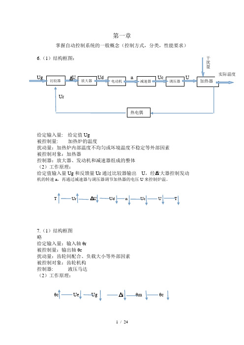
掌握自动控制系统的一般概念(控制方式,分类,性能要求)给定输入量: 给定值Ug 被控制量: 加热炉的温度扰动量:加热炉内部温度不均匀或坏境温度不稳定等外部因素 被控制对象:加热器控制器:放大器、发动机和减速器组成的整体 (2)工作原理:给定值输入量Ug 和反馈量Ur 通过比较器输出 U机的转速n ,再通过减速器与调压器调节加热器的电压U 来控制炉温。
T7.(1)结构框图 略给定输入量:输入轴θr 被控制量:输出轴θc扰动量:齿轮间配合、负载大小等外部因素 被控制对象:齿轮机构 控制器: 液压马达 (2)工作原理:θUe Ug θc掌握系统微分方程,传递函数(定义、常用拉氏变换),系统框图化简;1.(a)⎪⎪⎪⎩⎪⎪⎪⎨⎧=+=+=dtdu C i R u i i u iR u t ct ct t r )(02)(0)(01)()2......()1(.......... 将(2)式带入(1)式得:)()(01)(021)(0t r t t t u dtdu C R u R R u =++拉氏变换可得)()(01)(0221s r s s U CsU R u R R R =+⎪⎪⎭⎫ ⎝⎛+整理得21212)()(0)(R R Cs R R R U U G S r S s ++==1.(b)⎪⎪⎪⎩⎪⎪⎪⎨⎧=+=+=dtdi L u R u i i u iR u Lt o t Lt t r )(2)(0)(01)()2........()1......(.......... 将(2)式代入(1)式得)()(0221)(01t r t t u u R R R dt u L R =++⎰ 拉氏变换得)()(0221)(01s r s s U U R R R U Ls R =++ 整理得LsR R R R LsR U U G s r s s )(21212)()(0)(++==2.1)微分方程求解法⎪⎪⎪⎩⎪⎪⎪⎨⎧+=-=+=-31224203221211111Rudt du c Ruu R u R u Rudt du c R u u c c c c c c c c r中间变量为1c u,2c u及其一阶导数,直接化简比较复杂,可对各微分方程先做拉氏变换⎪⎪⎪⎩⎪⎪⎪⎨⎧+=-=+=-3122423221211111RUU sc R U U RU R U RUU sc R U U c c c c c c c c r移项得⎪⎪⎪⎩⎪⎪⎪⎨⎧++==++=2432432211211)11()111(c c c c rU R R sc RU R RU U U R R sc R U可得11121432432143214320)111()11(RR sc R R R R sc R R R R R R R R sc R R sc Ur U ++++=++++=2)复阻抗法⎪⎪⎪⎪⎪⎪⎪⎩⎪⎪⎪⎪⎪⎪⎪⎨⎧+=+++=++=2211232223234212121111*11*11sc R sc z U sc R sc z U sc R sc R R z sc R sc R R z r解得:1112143243RR sc R R R R sc R R Ur U ++++=3.分别以m 2,m 1为研究对象(不考虑重力作用)⎪⎪⎩⎪⎪⎨⎧--=---=11212121121222222)()()(ky dty y d c dt y d m dty y d cdt dy c t f dt y d m 中间变量含一阶、二阶导数很难直接化简,故分别做拉氏变换⎪⎩⎪⎨⎧--=---=112112112122222)()()(kY Y Y s c Y s m Y Y s c sY c s F Y s m 消除Y1中间变量21211222))1(()(Yk s c s m sc s c s c s m s F s++-++=10.系统框图化简:o (s)o (s)o (s)1.综合点前移,分支点后移o (s)1231133221231133221133()()()()()(1()())(1()())()()()()()1()()()()()()()()()()o i X s G s G s G s X s G s H s G s H s G s H s G s G s G s G s H s G s H s G s H s G s H s G s H s =+++=++++11.系统框图化简:2.交换综合点,合并并联结构3.化简12341234243114412123123212343231344()()()()()()1()()()()(()/()()()/()()()/()())()()()1()()()()()()()()()()()()()()(o i X s G s G s G s G s X s G s G s G s G s H s G s H s H s G s G s H s G s G s G s G s G s G s G s G s H s G s G s G s G s H s G s G s H s G s G s H =+--+=+--+)s第三章掌握时域性能指标,劳斯判据,掌握常用拉氏变换-反变换求解时域响应,误差等2.(1)求系统的单位脉冲响应12()()()TsY(s)+Y(s)=KX(s)X(s)=1Y(s)=1()=20e t tTT y t y t Kx t K Ts k w t eT•--+=+=已知系统的微分方程为:对微分方程进行零初始条件的拉氏变换得当输入信号为单位脉冲信号时,所以系统输出的拉式变换为:进行拉式反变换得到系统的时域相应2.(2)求系统的单位阶跃响应,和单位斜坡响应22()()()TsY(s)+Y(s)=KX(s)X(s)=5Y(s)=1111110()10-10e ;1X(s)=Y(s)=t T y t y t Kx t KTK Ts Ts Ts sK s s s y t s •-+=+++=-=-=已知系统的微分方程为:对微分方程进行零初始条件的拉氏变换得当输入信号为单位阶跃信号时,所以系统输出的拉式变换为:进行拉式反变换得到系统的时域相应当输入信号为单位阶跃信号时,所以系统输出的拉式变换为:22222110550111()510t+5e ;t K K KT T K Ts s s s Ts s s Ts y t -=-+=-++++=-+进行拉式反变换得到系统的时域相应9.解:由图可知该系统的闭环传递函数为22()(22)2b kG s s k s kτ=+++又因为:2%0.20.52222r n n t k kσξωτω⎧⎪==⎪-⎪==⎨⎪=+⎪⎪=⎩ 联立1、2、3、4得0.456; 4.593;10.549;0.104;n K ξωτ==== 所以0.76931.432p ds nt s t sπωξω====10.解:由题可知系统闭环传递函数为210()1010b kG s s s k=++ 221010n nk ξωω=⎧⎪⎨=⎪⎩ 当k=10时,n ω=10rad/s;ξ=0.5;所以有%16.3%0.3630.6p s n e t s t sπξσξω-⎧⎪==⎪⎪⎪==⎨⎪⎪⎪==⎪⎩当k=20时,n ω=14.14rad/s;ξ=0.35;所以有%30.9%0.2430.6ps n e t s t sπξσξω-⎧⎪==⎪⎪⎪==⎨⎪⎪⎪==⎪⎩当0<k<=2.5时,为过阻尼和临界阻尼,系统无超调,和峰值时间;其中调整时间不随k 值增大而变化;当k>2.5时,系统为欠阻尼,超调量σ%随着K 增大而增大,和峰值时间pt 随着K 增大而减小;其中调整时间s t 不随k 值增大而变化;14.(1)解,由题可知系统的闭环传递函数为32560-1403256000056014014k 00()1440kb k k k s s s ks kG s s s s k->><<∴=+++∴⎧⎨⎩∴劳斯表系统稳定的充要条件为:14.(2)解,由题可知系统的闭环传递函数为320.60.8832430.60.80010.20.80.210.8k 00(1)()(1)k b k k k kk s s s ks k s G s s s k s k-->>>>-∴+=++-+∴⎧⎪⎨⎪⎩∴劳斯表系统稳定的充要条件为:20.解:由题可知系统的开环传递函数为(2)()(3)(1)k k s G s s s s +=+-当输入为单位阶跃信号时,系统误差的拉氏变换为11()111()lim limlim ()0k ss k ss ss s s k s ss G s E G s ssE G s e →→→+=+===∞∴=又根据终值定理e 又因为25.解:由题可知系统的开环传递函数为1212()(1)(1)k k k G s T s T s =++当输入为给定单位阶跃信号时1()i X s s=,系统在给定信号下误差的拉氏变换为1101211211()111()lim limlim ()11k ss k ss ss s s k s ss G s E G s ssE G s k k e k k →→→+=+===∴=+又根据终值定理e 又因为当输入为扰动信号时1()N s s=,系统扰动信号下误差的拉氏变换为221210122212212121()111()lim limlim ()111k ss k ss ss s s k s ss ss ss ss k G s k T s E G s ssE G s k k k e k k k e e e k k →→→-+-+=+===-∴=+-∴=+=+又根据终值定理e 又因为第四章 根轨迹法掌握轨迹的概念、绘制方法,以及分析控制系统4-2 (2)G(s)=)15.0)(12.0(++s s s K;解:分析题意知:由s(0.2s+1)(0.5s+1)=0得开环极点s 1=0,s 2=-2,s 3=-5。
自动控制原理题目含答案

自动控制原理题目含答案---------------------------------------《自动控制原理》复习参考资料一、基本知识11、反馈控制又称偏差控制,其控制作用是通过输入量与反馈量的差值进行的。
2、闭环控制系统又称为反馈控制系统。
3、在经典控制理论中主要采用的数学模型是微分方程、传递函数、结构框图和信号流图。
4、自动控制系统按输入量的变化规律可分为恒值控制系统、随动控制系统与程序控制系统。
5、对自动控制系统的基本要求可以概括为三个方面,即:稳定性、快速性和准确性。
6、控制系统的数学模型,取决于系统结构和参数, 与外作用及初始条件无关。
7、两个传递函数分别为G1(s)与G2(s)的环节,以并联方式连接,其等效传递函数为G1(s)+G2(s),以串联方式连接,其等效传递函数为G1(s)*G2(s)。
8、系统前向通道传递函数为G(s),其正反馈的传递函数为H(s),则其闭环传递函数为G (s)/(1- G(s)H(s))。
9、单位负反馈系统的前向通道传递函数为G(s),则闭环传递函数为G(s)/(1+ G(s))。
10、典型二阶系统中,ξ=时,称该系统处于二阶工程最佳状态,此时超调量为%。
11、应用劳斯判据判断系统稳定性,劳斯表中第一列数据全部为正数,则系统稳定。
12、线性系统稳定的充要条件是所有闭环特征方程的根的实部均为负,即都分布在S平面的左平面。
13、随动系统的稳态误差主要来源于给定信号,恒值系统的稳态误差主要来源于扰动信号。
14、对于有稳态误差的系统,在前向通道中串联比例积分环节,系统误差将变为零。
15、系统稳态误差分为给定稳态误差和扰动稳态误差两种。
16、对于一个有稳态误差的系统,增大系统增益则稳态误差将减小。
17、对于典型二阶系统,惯性时间常数T愈大则系统的快速性愈差。
越小,即快速性18、应用频域分析法,穿越频率越大,则对应时域指标ts越好19最小相位系统是指S右半平面不存在系统的开环极点及开环零点。
- 1、下载文档前请自行甄别文档内容的完整性,平台不提供额外的编辑、内容补充、找答案等附加服务。
- 2、"仅部分预览"的文档,不可在线预览部分如存在完整性等问题,可反馈申请退款(可完整预览的文档不适用该条件!)。
- 3、如文档侵犯您的权益,请联系客服反馈,我们会尽快为您处理(人工客服工作时间:9:00-18:30)。
槽式消化机自动控制原理
石家庄鸿宇化学工程技术有限公司齐建军李嵘
根据石灰消化工艺特点,在生产过程中,石灰乳的含量需要相对稳定,消化过程中设计应满足以下条件:
1.生石灰经消化后为含量较高的Ca(OH)2浓浆,然后加水调制成含量为一定浓度的Ca(OH)2悬浊液;
2.消化过程应尽可能进行高温消化,利用高温充分分解过烧石灰,提高消化收率。
3.消化机应实现自动进料、自动配水、流量可控、做到成品含量可控。
4.增加三废处理设备,尽可能将污水回用
工艺流程简介:
为满足工艺要求,设计采用了以下流程。
流程图
石灰乳生产单元分为原料车间和消化车间,在原料车间储存的原料生石灰,由装载机经振动蓖加入地下料仓中加入料仓中,并均匀进入破碎机中破碎至3cm左右,在破碎过程中产生的粉尘由引风机经破碎机上部的除尘罩引至车间外部的除尘塔中除尘,除尘用水经沉降后由泵抽取循环使用,沉降池中沉积的氢氧化钙定期清理。
破碎的生石灰经斗式提升机提升并经输送机送入位于消化车间消化机上部的料仓;由料仓下部的给料器均匀送入位于二层平台的消化机,同时以灰水比1:3
的比例向消化机中加入工艺水。
进入消化机中生石灰和水在搅拌桨叶高强度搅拌下进行消化反应,水化成乳液。
大部分残渣由消化机出渣口排出和振动筛中筛分出灰渣被输送机送至车间外的粗渣池。
在消化过程中由于消化放热,消化机中的浆液温度逐渐提升至85℃以上。
经过滤后的粗浆液(约20-25°Be,)自流进入调浆罐中进行调浆至18-20°Be,,再由泵送至旋液除渣器,分离出不溶性的灰渣送入车间外细渣池。
经旋液除渣器处理后的浆液18°Be,进入精浆罐中加水配制Ca(OH)2含量至12°Be,再由泵抽取送入车间外储浆罐备用。
室外渣池中的灰渣,经沉降后,污水由污水泵抽至消化机中做为消化用水使用。
设备简介:
石灰乳制取设备为我公司设计、制造的HYXH-40B型槽式消化机,该消化机的特点是整体密闭,设备设计有两级高强度搅拌,可满足工艺要求的高温、高浓度消化,消化机内安装有出渣机,将不溶性灰渣排出机外。
消化机结构图
消化机自动控制原理:
物料经冲板流量计送至消化机中,消化机启动,根据物料流量反馈至PLC中,热水节调阀开启,向消化机中加入65℃热水,当消化机中有浆液溢出时,由浓度计(密度计)进行浓度检测,调节阀的开度转而由浓度计反馈信号调节,消化机出口的浆液浓度稳定在27%(20°Be)当消化机内温度达到95℃时,冷水调节阀开启向消化机内逐渐加入冷水,并逐渐关闭热水调节阀,使消化机内温度保持在95℃以上。
消化机自动控制原理图
工艺水流量计算:
按消化机每小时最大消化4吨纯氧化钙计算,工艺水流量按1:3-4配比,最大流量应为>12m3/ h.,最少消化量按1吨计算,最小流量应为2-3m3/ h..
附:石灰乳悬浮液浓度与波美度、密度关系表。