Faq-100401-PCB MS DS协同仿真
软通动力扬帆富设备开发板硬件指导手册说明书

软通动力信息技术(集团)股份有限公司目录第一章产品概述 (2)1.1适用范围 (2)1.2产品概述 (2)1.3产品特点 (2)1.4外观及接口示意图 (4)正面/背面 (4)第二章基本功能列表 (5)第三章PCB尺寸和接口布局 (6)3.1PCB尺寸图 (6)3.2接口参数说明 (6)第四章电气性能 (14)第五章使用注意事项 (15)第一章产品概述1.1.1.1适用范围扬帆开发板属于自助终端主板,普遍适用于:互动广告机、互动数字标牌、智能自助终端、智能零售终端、工控主机、机器人设备等。
1.2.1.2产品概述扬帆开发板采用瑞芯微RK3399(双Cortex-A72大核+四Cortex-A53小核)六核64位超强CPU,搭载Openharmony系统,主频最高达1.8GHz。
采用Mali-T860GPU,支持4K、H265/H264视频解码。
多路视频输出和输入,性能更强,速度更快,接口更丰富,是您在人机交互、智能终端、工控项目上的最佳选择。
1.3.1.3产品特点RK3399超强CPU,速度更快,性能更强●搭载OpenHarmony●系统支持WIFI,单天线●网口设计,支持1000M网口●内置PCI-E接口●丰富的扩展接口.六路USB接口、可扩展串口、GPIO及ADC接口,可以满足市场上各种外设的要求●高清晰度,支持eDP/HDMI OUT等接口的LCD显示屏●支持多种主流触摸屏1.4.1.4外观及接口示意图1.5.正面/背面第二章基本功能列表主要功能参数板卡尺寸146mm*104mm、板厚1.6mmCPU RK3399、六核、主频最高达1.8GHzGPU四核Mali-T860GPU高性能GPU操作系统OpenHarmony内存/存储4G(2G可选)/32G(8G/16G/64G可选)HDMI输出1个HDMI2.0a支持4K60Hz显示、支持HDCP1.4/2.2eDP输出可直接驱动1920x1080分辨率的eDP接口液晶屏视频格式支持支持MP4图片格式支持支持BMP、JPEG、PNG、GIF音频输出功放输出(支持左右声道输出,内置双4R/20W、8R/10W功放)耳机支持一路耳机接口USB接口1路USB3.0OTG、1路USB3.0Host+4路HUB串口/扩展接口1路TTL、1路DEBUG、1路IIC、4路GPIO接口、1路ADC WIFI内置WIFI、单天线以太网支持1000M以太网PCIE接口预留2.第三章PCB尺寸和接口布局2.1.3.1PCB尺寸图PCB:8层板,板厚1.6mmPCBA:L*W=146mm*104mm,MAX H=12.0+/-0.3mm螺丝孔规格:∮3.5mm x42.2.3.2接口参数说明图片标注说明:插座接口图片上圆圈处“Ο”表示第一脚。
智能融合cSoC:ACE序列控制使用纤维和MSS说明书

Application Note AC366May 20191© 2019 Microsemi Corporation SmartFusion cSoC: ACE Sequencing Control Using Fabric and MSSTable of ContentsIntroductionThe mixed signal blocks found in the SmartFusion ® customizable system-on-chip (cSoC) devices are controlled and connected to the rest of the system via a dedicated processor called the analog compute engine (ACE). The ACE is built to handle the sampling, sequencing, and post-processing of the ADCs,DACs, and signal conditioning blocks (SCBs). For a larger deterministic synchronization between the sampling and custom fabric logic, the sample sequencing in the ACE is controlled through the microprocessor subsystem (MSS) or FPGA fabric logic.This application note provides the two design examples which allow deterministic synchronization between the sampling essential steps:•"Design Example 1: ACE Sequencer Using Fabric Logic" on page 3•"Design Example 2: Simultaneous Sampling Using the MSS" on page 5This application note also assumes that you are familiar with the SmartFusion analog block. Refer to the SmartFusion Programmable Analog User’s Guide for more information.Sample Sequencing in ACEThe ACE in the SmartFusion cSoC is made up of two major blocks:•Sample sequencing engine (SSE)•Post processing engine (PPE)The SSE offers a flexible configuration of the analog front end (AFE) resources (analog inputs and monitors, comparators, ADCs, and DACs), as well as a variety of simple and sophisticated sample sequencing. The PPE is a self sufficient block that allows the data processing such as linear transformation, filtering, and thresholds comparisions, etc. The ACE also has an interface with the AFE and the MSS/FPGA fabric.Introduction . . . . . . . . . . . . . . . . . . . . . . . . . . . . . . . . . . . . . . . . . . . . . . . . 1Sample Sequencing in ACE . . . . . . . . . . . . . . . . . . . . . . . . . . . . . . . . . . . . . . . 1Design Example . . . . . . . . . . . . . . . . . . . . . . . . . . . . . . . . . . . . . . . . . . . . . . 3Special Consideration During the Simultaneous Sampling . . . . . . . . . . . . . . . . . . . . . . . . 6Conclusion . . . . . . . . . . . . . . . . . . . . . . . . . . . . . . . . . . . . . . . . . . . . . . . . 7Appendix A: ACE Configuration and Connectivity . . . . . . . . . . . . . . . . . . . . . . . . . . . . 8Appendix B: Special ACE Register for Design Example . . . . . . . . . . . . . . . . . . . . . . . . 12Appendix C: Configuration for Simultaneous Sample Procedure . . . . . . . . . . . . . . . . . . . . 13Appendix D: ACE Configuration and Procedure for Design Example 2 . . . . . . . . . . . . . . . . 14Appendix E: Design Files . . . . . . . . . . . . . . . . . . . . . . . . . . . . . . . . . . . . . . . . 14List of Changes . . . . . . . . . . . . . . . . . . . . . . . . . . . . . . . . . . . . . . . . . . . . . 15SmartFusion cSoC: ACE Sequencing Control Using Fabric and MSS2It interfaces with the MSS and fabric is through the APB3 bus as depicted in Figure1.Figure2 provides an overview of the sample sequencing engine (SSE) block and its interfaces to PPE, APB3, ADCs, DACs, and ACB. The SSE block has the following:•The sample sequencing instruction (SSI) unit multiplexes between APB3 and program instruction in SRAM, access to the analog fabric registers.•Time division multiplexing finite state machine (TDM FSM): Creates the timeslots for each of the three ADCs, as well as a shared timeslot for APB3 or PPE accesses. The ADC timeslots are allocated during the ACE configuration in the SmartDesign.•APB3/PPE interface: Arbitrates the SSE access between the APB3 and PPE.•24-bit phase accumulators: Front-end accumulators for the three SDDs.Figure 1 • Overview of ACE Architecture and InterfacesFigure 2 • Overview of ACE Architecture and InterfacesDesign Example 3The TDM FSM block (shown in Figure 2 on page 2) implements a mechanism to sequence through the ADCs. It allows the equal access by three separate program counters (PC0, PC1, and PC2) in the SSE and the APB3/PPE master. The SSE uses a separate program counters (PC) for sequencing and controlling each ADCs independently. When controlling the SSE from the APB3 master, the master needs to honor the wait-states generated by the PREADY signal during the normal operation of the SSE TDM timeslot counter.Note:When the TDM timeslot counter is enabled for normal operation of the SSE block, there are alwaysfour timeslots, regardless of whether there are one, two, or three ADC instances in a specificdevice.The TDM FSM is controlled by FABACETRIG signal or SSE_TS_CTRL register when bit 0 of•SSE_TS_CTRL register or FABACETRIG is set to 1, it enables all 4 timeslots •SSE_TS_CTRL or FABACETRIG set to 0, it only enables access to the APB3 master – this fixesthe PREADY signal high to allow the zero-wait state access to the APB3 masterThe SmartFusion cSoC devices also have the capability of simultaneous sampling on different ADCs.Simultaneous synchronized ADC conversion control register (ADC_SYNC_CONV) allows for a single program to issue the synchronized start instructions for all ADCs.Design ExampleThis section describes the design examples. This application note shows two design examples of controlling the ACE sequencer using the fabric logic and MSS.The first design example shows a master in fabric, uses the FABACETRIG to access the APB3 interface in the ACE, and then control the SSE sampling. The second design example shows the simultaneous sampling on multiple ADCs using the MSS.Note:The timeslots do not have any capability neither to block each other nor to signal each other. So,you need to use the special consideration during the simultaneous sampling. For more details, referto "Special Consideration During the Simultaneous Sampling" on page 6.Design Example 1: ACE Sequencer Using Fabric LogicThis design example shows a master in fabric controlling the SSE timeslot. It uses the FABACETRIG (refer to "Appendix A: ACE Configuration and Connectivity" on page 8) signal to access the APB3interface in ACE and then control the SSE sampling. Figure 3 illustrates the concept of using the FABACETRIG to control the SSE sampling.Figure 3 •Timing Diagram showing FABACETRIG to Control SSE SamplingSmartFusion cSoC: ACE Sequencing Control Using Fabric and MSS4The fabric APB master is responsible for:•Detecting that the ACE has reached the end of a sequence through the ACEFLAGS signal (ACEFLAGS are connected to ACE_TRIGGER in fabric).•Assert the FABACETRIG signal to the ACE to halt the SSE time division multiplexing.•Clear the *_PPE_DONE notification flag by writing to the ACE PPE_FLAGS0_IRQ_CLR registers (refer to "Appendix B: Special ACE Register for Design Example" on page 12).•Notifying the rest of the fabric logic to begin a transaction. This is simulated in this design with the ENABLE_PWM signal that enable a CorePWM IP.•Re-enabling the ACE sequencer by writing to the program counter enables bit and writing the next program counter address (refer to "Appendix B: Special ACE Register for Design Example"on page 12). The program counter address is found in the<project>\firmware\drivers_config\mss_ace\ace_config.c file.The starting loop address for a given procedure is specified in the ace_procedure_dest_t table.For example, in the structure below, “2” is the starting loop address for this procedure.{g_ace_sse_proc_0_name, /* const uint8_t * p_sz_proc_name */ 2, /* uint16_t sse_loop_pc */ 0, /* uint16_t sse_load_offset */ sizeof(g_ace_sse_proc_0_sequence) / sizeof(uint16_t), /* uint16_tsse_ucode_length */g_ace_sse_proc_0_sequence, /* const uint16_t * sse_ucode */ 0 /* uint8_t sse_pc_id */ },The block diagram of the design example is shown in Figure4.Figure 4 •Top Level Block Diagram of ACE Sequencer Using Fabric LogicDesign Example 5The design example is available for downloading at/download/rsc/?f=A2F_AC366_DF .The following waveform (Figure 5) shows the ACE and fabric APB3 master interacting.Design Example 2: Simultaneous Sampling Using the MSSThe second design example shows the simultaneous sampling on multiple ADCs using the MSS.Figure 6 shows the ACE configuration used in this design. "Appendix C: Configuration for Simultaneous Sample Procedure" on page 13 shows the option to enable simultaneous sampling in the ACE configurator.Figure 5 • ACE and Fabric APB3 Master SimulationFigure 6 •ACE Configuration for Simultaneous Sampling Design ExampleSmartFusion cSoC: ACE Sequencing Control Using Fabric and MSS6The block diagram of the design example is shown in Figure 7. The design exampleLibero ® System-on-Chip (cSoC) software projects are available for downloading at/download/rsc/?f=A2F_AC366_DFSpecial Consideration During the Simultaneous SamplingThe ADC timeslots have the capability to access and control any of the ADCs. However, these timeslots do not have the capability to block or signal each other. Therefore, essentially they get two clock cycles each to execute the available microcode instruction, and then the SSE moves to the next timeslot. Due to this architectural advantage, you should take care of the following situation where the results might be wrong.Assume that both the timeslot 0 and timeslot 1 are sampling the ADC0 channels. This means that the timeslot 0 executes its sample instructions and asserts the ADCSTART for the ADC0 on channel X. The ADC0 begins that process. Now the timeslot 1 is activated (after two clocks) and it also has an instruction that uses ADC0. There is no mechanism in the SSE to explicitly query whether the ADC is busy or not.Therefore, when that timeslot sees the sample microcode, it asserts another ADCSTART for the ADC0on channel Y . Consequently, now you have the timeslot 0 waiting for a data valid from the ADC0 for channel X, and the timeslot 1 is waiting for a data valid from ADC0 for channel Y . When the ADC0 finally finishes and returns the data valid, both timeslots move onto their next respective microcode instructions.However, only one of them have the sample proper data. Only one piece of data is sent to the PPE, since it is the ADC data valid that is used to write into the ADCFIFO and only one ADC data valid signal allocated per ADC.Figure 7 •Top Level Block Diagram of Simultaneous Sampling Design ExampleConclusionA technique is shown to solve this simultaneous sampling in "Design Example 2: Simultaneous SamplingUsing the MSS" on page 5. Please refer to the technique below that solves the problem of simultaneoussampling on the same ADC.Note:The two ADCs’ procedure uses the simultaneous sample.1.After power-on reset,–The MSS initializes the various peripherals.–The MSS loads the simultaneous sampling procedures into SSE to sample two channels per ADC (total four samples expected).–In the FPGA, FABACETRIG is set to 1.–The MSS sends an enable signal through a GPIO to FPGA (to convey that it can start the sampling sequence).2.On seeing the GPIO set, FPGA starts 10 KHz counter.3.On rising of 10 KHz, it brings FABACETRIG low after 1 s.4.The ACE starts simultaneous sampling and interrupts M3 when samples are available. Theprocedure disables the timeslot (PCx_EN = 0).5.The M3 gets the data from the ACE into variables and loads both the sequential samplingprocedures (seq_adc00 and seq_adc01). Sequential sampling starts.6.On completion, the M3 gets two interrupts for both the ADCs. The procedure disables both thetimeslots (PCx_EN = 0). On serving both the interrupts (reading sample values), M3 does a writeto fabric to signal end of sequence.7.On detecting the write from M3, FPGA brings FABACETRIG high.8.The M3 loads simultaneous sampling procedure (two ADCs).9.Sequence repeats from step 3.ConclusionThis application note provides the design examples of using the fabric logic or MSS to control the SSEsampling. This can be used to allow the deterministic synchronization.7SmartFusion cSoC: ACE Sequencing Control Using Fabric and MSS8Appendix A: ACE Configuration and ConnectivityStep1. MSS ACE Configuration for Design Example 11.Inside the ACE Configurator, click the Advanced Options dialog box. Select the ExposeFABACETRIG port checkbox. This exposes the FABACETRIG port on the ACE block enabling the fabric logic to halt the ACE sequencing.2.Create the ACE design as normal. Configure the ACE services and threshold flags.Figure 8 •Expose FABACETRIG Port CheckboxAppendix A: ACE Configuration and Connectivity 93.Sequence your analog services in the ACE configurator Controller tab.You can initiate a signal to the fabric when the end of this sequence is reached. You can accomplish this by reconfiguring the ADCDirectInput_2 service to assert a signal on completing its post processing. Use this particular service, as it is the last one in this sequence.4.Configure the ADCDirectInput_2 service and select the Assert flag when post processingcompleted checkbox.Figure 9 • ACE Configurator ControllerFigure 10 •Configure the ADCDirectInput_2 ServiceSmartFusion cSoC: ACE Sequencing Control Using Fabric and MSS10Selecting this checkbox creates a flag signal named <Signal name>:PPE_DONE automatically.5.Go into the Flags tab and assign it to the bit position of your choice. In the example, you haveassigned the new PPE_DONE indication to bit 15.Figure 11 •Assigning ADCDirectInput_2_PPE_DONE to Bit 15Appendix A: ACE Configuration and Connectivity 116.Click FPGA_FLAGS in the left-hand treeview and select the Expose these signals asACEFLAGs checkbox.7.Click OK , the ACE instance in the MSS configurator window is displayed, as shown in Figure 13.Figure 12 • Exposing ACEFLAGsFigure 13 •ACE Instance in the MSS ConfiguratorSmartFusion cSoC: ACE Sequencing Control Using Fabric and MSS12Appendix B: Special ACE Register for Design ExampleNote:Table 1 shows the register description for the Program Counter 0. The registers are duplicated forProgram Counter 1 and Program Counter 2.Table 1 • Special ACE Register for Design Example ADDRRegister Name Description 0x4002122c PPE_FLAGS0_IRQ_CLR These write-only bits are used to clear corresponding bits in thePPE_FLAGS0_IRQ register. Writing a 1 to any of the bits clears thecorresponding bits in the PPE_FLAGS0_IRQ register, while writing a 0to any of the bits does not have an effect. In the event that writing a 1to these clear bits coincides with a set event in the PPE_FLAGS0_IRQregister, the set event shall have higher priority.0x40020040PC0_LO Program Counter 0 points to address the next sample sequenceinstruction for ADC0. A write to this register causes the timeslot 0 tounconditionally jump to the SSE RAM address PC[7:0], which includesRAM addresses from 0 to 255 inclusive.0x40020044PC0_HI Program Counter 0 points to address the next sample sequenceinstruction for ADC0. A write to this register causes timeslot 0 tounconditionally jump to the SSE RAM address 256+PC[7:0], whichincludes RAM addresses from 256 to 511 inclusive.0x40020048PC0_CTRLOnly bit 0 is used. When set to 1, Program Counter 0 is enabled andwhen set to 0, Program Counter 0 is disabled (stop).Appendix C: Configuration for Simultaneous Sample Procedure 13Appendix C: Configuration for Simultaneous Sample Procedure1.In the Configurator ACE window, click the Controller tab.2.From the Insert Operating Sequence Slot drop-down list, select SIMULTANEOUS SAMPLE.The Configure ’SIMULTANEOUS SAMPLE’ window is displayed.3.Select the services you want to sample simultaneously and click OK .Figure 14 • Adding Simultaneous Sample ProcedureFigure 15 •Selecting Services for Simultaneous SampleSmartFusion cSoC: ACE Sequencing Control Using Fabric and MSS14Appendix D: ACE Configuration and Procedure for Design Example 2The ACE controller procedures are:ADC0_MAIN :•Stop the sequence in this time slot ADC1_MAIN :•Stop the sequence in this time slot ADC2_MAIN :•Stop the sequence in this time slot seq_adc00:•Sample VoltageMonitor_2•Sample VoltageMonitor_3•Assert Interrupt on GP1•Stop the sequence in this time slot seq_adc10:•Sample VoltageMonitor_6•Sample VoltageMonitor_7•Assert Interrupt on GP0•Stop the sequence in this time slot two ADCs:•Simultaneously Sample VoltageMonitor_0 VoltageMonitor_4•Assert Interrupt on GP0•Simultaneously Sample VoltageMonitor_1 VoltageMonitor_5•Stop the sequence in this time slot Appendix E: Design FilesYou can download the design files from the Microsemi SoC Products Group website:/download/rsc/?f=A2F_AC366_DF .List of Changes 15List of ChangesThe following table lists critical changes that were made in each revision of the document.Revision*Changes Page Revision 1(January 2012)Updated Figure 4 (SAR 35795).4Modified the section "Design Example" (SAR 35795).3Updated Figure 7 (SAR 35795).6Modified the section "Appendix E: Design Files" (SAR 35795).14Revision 2(May 2019)Modified the sections:Design Example 1: ACE Sequencer Using Fabric LogicDesign Example 2: Simultaneous Sampling Using the MSS (SAR 51242).5 and 6Note:*The revision number is located in the part number after the hyphen. The part number is displayed at the bottomof the last page of the document. The digits following the slash indicate the month and year of publication.Microsemi HeadquartersOne Enterprise, Aliso Viejo,CA 92656 USAWithin the USA: +1 (800) 713-4113 Outside the USA: +1 (949) 380-6100 Sales: +1 (949) 380-6136Fax: +1 (949) 215-4996Email: *************************** ©2019 Microsemi, a wholly owned subsidiary of Microchip Technology Inc. All rights reserved. Microsemi and the Microsemi logo are registered trademarks of Microsemi Corporation. All other trademarks and service marks are the property of their respective owners. Microsemi makes no warranty, representation, or guarantee regarding the information contained herein or the suitability of its products and services for any particular purpose, nor does Microsemi assume any liability whatsoever arising out of the application or use of any product or circuit. The products sold hereunder and any other products sold by Microsemi have been subject to limited testing and should not be used in conjunction with mission-critical equipment or applications. Any performance specifications are believed to be reliable but are not verified, and Buyer must conduct and complete all performance and other testing of the products, alone and together with, or installed in, any end-products. Buyer shall not rely on any data and performance specifications or parameters provided by Microsemi. It is the Buyer’s responsibility to independently determine suitability of any products and to test and verify the same. The information provided by Microsemi hereunder is provided “as is, where is” and with all faults, and the entire risk associated with such information is entirely with the Buyer. Microsemi does not grant, explicitly or implicitly, to any party any patent rights, licenses, or any other IP rights, whether with regard to such information itself or anything described by such information. Information provided in this document is proprietary to Microsemi, and Microsemi reserves the right to make any changes to the information in this document or to any products and services at any time without notice.About MicrosemiMicrosemi, a wholly owned subsidiary of Microchip T echnology Inc. (Nasdaq: MCHP), offers a comprehensive portfolio of semiconductor and system solutions for aerospace & defense, communications, data center and industrial markets. Products include high-performance and radiation-hardened analog mixed-signal integrated circuits, FPGAs, SoCs and ASICs; power management products; timing and synchronization devices and precise time solutions, setting the world's standard for time; voice processing devices; RF solutions; discrete components; enterprise storage and communication solutions, security technologies and scalable anti-tamper products; Ethernet solutions; Power-over-Ethernet ICs andmidspans; as well as custom design capabilities and services. Learn more at .51900234-2/05.19。
智能融合cSoC:多通道FFT共享处理器使用FPGA纤维说明书

Application Note AC381February 20121© 2012 Microsemi Corporation SmartFusion cSoC: Multi-Channel FFT Co-Processor Using FPGA FabricTable of ContentsIntroductionThe SmartFusion ® customizable system-on-chip (cSoC) device integrates FPGA technology with a hardened ARM ® Cortex™-M3 processor based microcontroller subsystem (MSS) and programmable high-performance analog blocks built on a low power flash semiconductor process. The MSS consists of hardened blocks such as a 100 MHz ARM Cortex-M3 processor, peripheral direct memory access (PDMA), embedded nonvolatile memory (eNVM), embedded SRAM (eSRAM), embedded FlashROM (eFROM), external memory controller (EMC), Watchdog Timer, the Philips Inter-Integrated Circuit (I 2C),serial peripheral interface (SPI), 10/100 Ethernet controller, real-time counter (RTC), GPIO block, fabric interface controller (FIC), in-application programming (IAP), and analog compute engine (ACE).The SmartFusion cSoC device is a good fit for applications that require interface with many analog sensors and analog channels. SmartFusion cSoC devices have a versatile analog front-end (AFE) that complements the ARM Cortex-M3 processor based MSS and general-purpose FPGA fabric. The SmartFusion AFE includes three 12-bit successive approximation register (SAR) ADCs, one first order sigma-delta DAC (SDD) per ADC, high performance signal conditioning blocks, and comparators. The SmartFusion cSoCs have a sophisticated controller for the AFE called the ACE. The ACE configures and sequences all the analog functions using the sample sequencing engine (SSE) and post-processes the results using the post processing engine (PPE) and handles without intervention of Cortex-M3 processor.Refer to the SmartFusion Programmable Analog User’s Guide for more details.This application note describes the capability of SmartFusion cSoC devices to compute the Fast Fourier Transform (FFT) in real time. The Multi Channel FFT example design can be used in medical applications, sensor network applications, multi channel audio Spectrum analyzers, Smart Metering, and sensing applications (such as vibration analysis).This example design uses the Cortex-M3 processor in the SmartFusion MSS as a master and the FFT processor in the FPGA fabric as a slave. All three of the SmartFusion cSoC A2F500’s ADCs are used for data acquisition. The example design uses Microsemi’s CoreFFT IP and the advanced peripheral bus interface (CoreAPB3). A custom-made APB3 interface has been developed to connect CoreFFT with the MSS via CoreAPB3. The Cortex-M3 processor uses the PDMA controller in the MSS for the data transfer and thus helps to free up the Cortex-M3 processor instruction bandwidth.A basic understanding of the SmartFusion design flow is assumed. Refer to Using UART with SmartFusion - Microsemi Libero ® SoC and SoftConsole Flow Tutorial to understand the SmartFusion design flow.Introduction . . . . . . . . . . . . . . . . . . . . . . . . . . . . . . . . . . . . . . . . . . . . . . . . 1Design Overview . . . . . . . . . . . . . . . . . . . . . . . . . . . . . . . . . . . . . . . . . . . . . 2Design Description . . . . . . . . . . . . . . . . . . . . . . . . . . . . . . . . . . . . . . . . . . . . 2Implementing Multi Channel FFT on EVAL KIT BOARD . . . . . . . . . . . . . . . . . . . . . . . . . 7Running the Design . . . . . . . . . . . . . . . . . . . . . . . . . . . . . . . . . . . . . . . . . . . . 8Conclusion . . . . . . . . . . . . . . . . . . . . . . . . . . . . . . . . . . . . . . . . . . . . . . . . 9Appendix A – Design Files . . . . . . . . . . . . . . . . . . . . . . . . . . . . . . . . . . . . . . . 10SmartFusion cSoC: Multi-Channel FFT Co-Processor Using FPGA Fabric2Design OverviewThis design example demonstrates the capability of the SmartFusion cSoC device to compute the FFT for multiple data channels. The FFT computation is a complex task that utilizes extensive logic resources and computation time. In general, for N number of channels, N number of FFT IP’s are needed to be instantiated, which in turn utilize more logic resources on the FPGA. A way to avoid this limitation is to use the same FFT logic for multiple input channels.This design illustrates the implementation of a Multichannel FFT to process multiple data channels through a single FFT and store FFT points in a buffer. The FFT computes the input data read from each channel and stores the N-point result in the respective channel’s allocated buffer. The channel multiplexing is done once each channel buffer has been loaded with the FFT length.Computing frequency components for a real time data of six channels is described in this application note. For sampling the input signals the AFE is used and the complex FFT computation is implemented in the fabric of the SmartFusion cSoC device. The Cortex-M3 processor in the MSS of the SmartFusion cSoC handles the buffer management and channel muxing.Figure 1 depicts the block diagram of six channel FFT co-processor in FPGA fabric.Design DescriptionThe design uses CoreFFT for computing the FFT results. You can download the core generator for CoreFFT at /soc/portal/default.aspx?r=4&p=m=624,ev=60.The design example uses a 512-point and 16-bit FFT. A custom-made APB3 interface has been developed to connect CoreFFT IP with the MSS’s FIC. The CoreFFT output data is stored in a 512x32FIFO within the fabric. The FIFO status signals are given in Table 1 on page 3. The status signals indicate that FFT is ready to receive data and data is available in the output of FIFO. These status signals are mapped to the GPIOs in the MSS. The Cortex-M3 processor can read the GPIOs to handle flow control in the data transfer process from the MSS to CoreFFT.Figure 1 • Multi Channel FFT Block DiagramDesign Description3Figure 2 shows the block diagram of logic in the fabric with custom-made APB3 bus.The data valid signal (ifiD_valid) is generated in custom logic whenever the master needs to write data into the input buffer of the FFT to process through the APB3 interface. The FFT_IP_RDY signal indicates the status of the input buffer of the FFT. If the input buffer is full, the FFT_IP_RDY goes low. The master can read the FFT_IP_RDY signal to get the FFT input buffer status. The FFT generates the processed data with a data valid signal (ifoY_valid). The processed data is stored in the FIFO. When FIFO is not ready to receive output data, it can stop the data fetching from the FFT by pulling down the ifiRead_y signal. The status signal FFT_OP_RDY is used to indicate to the master that processed data is available in the FIFO. FFT_OP_RDY goes High whenever processed data is available in the FFT output buffer.The master can use AEMPTY_OUT or EMPTY_OUT to determine whether the FIFO is empty and all the processed data has been read. Refer to the CoreFFT Handbook for more details on architecture and interface signal descriptions.Three ADCs are configured to have two channels, each channel with 100 ksps sampling rate. The external memory is used for input and output buffers. For each channel, one input buffer having length double to the length of FFT i.e. 1024 words and one output buffer having length equal to the length of FFT i.e. 512 words are used. After each channel's input buffer has 512 points required for the full length of the FFT, each channel, one after the other, streams its points from the FIFO through the FFT. During the FFT computational period, the sampled data values of each channel are stored in the second half of the input buffer. Once the FFT computations for the First half of input buffer completes then the points in the second half of the input buffer will be streamed to FFT. This operation utilizes a ping-pong method. The Cortex-M3 processor is used for data management, that is, buffering the sampled points and data routing or muxing of these values to the FFT computation block. Sampling of the real time data is done by the ACE. The PDMA handles the data transfer between the external SRAM (eSRAM) buffers and CoreFFT logic in FPGA fabric.Figure 2 • CoreFFT with APB Slave InterfaceTable 1 • FIFO Status Signals with DescriptionsSignalDescription FFT_IP_RDYFFT is ready to receive the Input from the master processor FFT_OP_RDYProcessed data is ready in output buffer of FFT AEMPTY_OUTOutput FIFO is almost empty EMPTY_OUT Output FIFO is emptySmartFusion cSoC: Multi-Channel FFT Co-Processor Using FPGA Fabric4Figure 3 shows the implementation of multi channel FFT on the SmartFusion cSoC device.Hardware ImplementationThe MSS is configured with an FIC, clock conditioning circuit (CCC), GPIOs, EMC and a UART. The CCC generates 80 MHz clock, which acts as the clock source. The FIC is configured to use a master interface with an AMBA APB3 interface. Four GPIOs in the MSS are configured as inputs that are used to handle flow control in data transfer from MSS to FFT coprocessor. The EMC is configured for Region 0as Asynchronous RAM and port size as half word. The UART_0 is configured for printing the FFT values to the PC though a serial terminal emulation program.ADC0, ADC1, and ADC2 are configured with 12-bit resolution, two channels and the sampling rate is set to approximately 100 KHz. Figure 4 on page 5 shows the ACE configuration window.Figure 3 • Implementation of Multi Channel FFT on the SmartFusion cSoCDesign Description5The APB wrapper logic is implemented on the top of CoreFFT and connected to CoreAPB3. A FIFO of size 512*32 is used to connect to CoreFFT output.CoreAPB3 acts as a bridge between the MSS and the FFT coprocessor block. It provides an advanced microcontroller bus architecture (AMBA3) advanced peripheral bus (APB3) fabric supporting up to 16APB slaves. This design example uses one slave slot (Slot 0) to interface with the FFT coprocessor block and is configured with direct addressing mode. Refer to the CoreAPB3 Handbook for more details on CoreAPB3 IP .For more details on how to connect FPGA logic MSS, refer to the Connecting User Logic to the SmartFusion Microcontroller Subsystem application note.The logic in the FPGA fabric consumes 18 RAM blocks out of 24. We cannot use eSRAM blocks for implementing CoreFFT as the transactions between these SRAM blocks and FFT logic are very high and are time critical.Figure 5 on page 6 illustrates the multi channel FFT example design in the SmartDesign.Figure 4 • Configure ACESmartFusion cSoC: Multi-Channel FFT Co-Processor Using FPGA Fabric6Table 2 summarizes the logic resource utilization of the design on the A2F500M3F device.Software ImplementationThe Cortex-M3 processor continuously reads the values from ACE and stores the values into the input buffers. If the first 512 points are filled then the processor initiates the FFT process. In the FFT process,the input buffers are streamed one after other to the CoreFFT with the help of PDMA. Using another channel of PDMA the output of FFT is moved to the corresponding channel output buffers.During the FFT process the Cortex-M3 processor stores the sampled values into the second half of the input buffers. Once the FFT process completes the first half of input buffer, then the second half of the input buffer are streamed to CoreFFT.Figure 5 • SmartDesign Implementation of Multi Channel FFTTable 2 • Logic Utilization of the Design on A2F500M3FCoreFFTOther Logic in Fabric Total Ram Blocks14418 (75%)Tiles 78424718313 (72.1%)Implementing Multi Channel FFT on EVAL KIT BOARD7The CALL_FFT(int *) application programmable interface (API) initiates the PDMA to transfer input buffer data to the FFT in the fabric. Before initiating PDMA it checks for FFT whether or not it is ready to read the data. The CALL_FFT(int *) API also checks if the output FIFO is empty so that all the FFT out values have been already read. When the input buffer has points equal to the full length of FFT, then it will be called.The Read_FFT() API initiates the PDMA for reading the FFT output values from FIFO in fabric to the corresponding output buffer. After reading all the values it calls the CALL_FFT() API with the next channel buffer to compute the FFT for next channel. This is done for all channels. After completion of FFT computation for all channels, if the continuous variable is not defined, it will print the FFT output values on the serial terminal. When FFT_OP_READY interrupt occurs then this API will be called.The GPIO1_IRQHandler() interrupt service routine occurs on the positive edge of FFT_OP_READY signal. It calls Read_FFT() API. This interrupt mechanism is used to read the sample values continuously while computing the FFT.If continuous variable is defined, then the FFT is computed without any loss of data samples. If #define continuous line is commented then after every completion of FFT computation of all channels the FFT output is printed on serial terminal. The printed values are in the form of complex numbers.The ping-pong mechanism is used for input data buffer to store the samples continuously. For each channel the input buffer length is double of the full FFT length. While computing the FFT for the first half of the buffer, the new sample values are stored in the second half of the input buffer and while computing the FFT for second half of buffer, the new sample values are stored in first half of the input buffer.Customizing the Number of ChannelsYou can change the design depending on your requirement. Configure the ADC (Figure 4 on page 5)with the required number of channels and required sampling rate. In SoftConsole project change the parameter value NUM_CHANNELS according to the ADC configuration. Edit the main code for reading ADCs data into buffers according to ACE configuration.Throughput CalculationsThe actual time to get 512 samples with 100 ksps is 5.12 ms. Each channel is configured to 100 ksps, so for every 5.12 ms we will have 512 samples in the input buffers.The actual time taken to compute the FFT for each channel is the sum of time taken to transfer 512points to CoreFFT, FFT computation time, and time to read FFT output to the output buffer.•Total time for computing FFT = (time taken to receive 512 data + computational latency for 512points + time taken to store 512 data) = 512*5 + 23292 + 512*5 =28412 clks •Time to compute FFT for 6 channels = 28412*6 = 170472 clksTime to compute FFT for six channels is 2.1309 ms (If CLK is 80 MHz). It is less than half the sample rate of 5.12 ms.If only one channel is configured with maximum sampling rate (600 ksps) then time to get 512 samples with 600 ksps is 0.853 ms. Time to compute FFT for these 512 samples is 0.355 ms. If you configure three ADCs with maximum sampling rate (1800 ksps) then time to compute the FFT for these three channels will be 1.065 ms which is higher than the sampling time. In this there is a loss of some samples.The design works fine up to 1440 ksps.Implementing Multi Channel FFT on EVAL KIT BOARDTo implement the design on the SmartFusion Evaluation Kit Board the FFT must be 256 point and 8 bit because the A2F200 device has less RAM blocks and logic cells. The ADC channels must be selected for only ADC0 and ADC1. Figure 6 on page 8 shows the implementation of multi channel FFT on the SmartFusion cSoC (A2F200M3F) device.SmartFusion cSoC: Multi-Channel FFT Co-Processor Using FPGA Fabric8Table 3 summarizes the logic resource utilization of the design with 256 points 8-bit FFT on A2F200M3F device.Running the DesignProgram the SmartFusion Evaluation Kit Board or the SmartFusion Development Kit Board with the generated or provided *.stp file (refer to "Appendix A – Design Files" on page 10) using FlashPro and then power cycle the board.For computing continuous FFT values for the all six signals sampled through the ADCs, uncomment the line #define continuous in the main program. The FFT output values are stored in the rdata buffer. This buffer is updated for every computation of FFT.For printing the FFT values on serial terminal (HyperTerminal or PuTTy), comment the line #define continuous in the main program.Figure 6 • Implementation of Multi Channel FFT on the SmartFusion Evaluation Kit BoardTable 3 • Logic Utilization of the Design on A2F200M3F DeviceCoreFFTOther Logic in Fabric Total Ram Blocks718 (100%)Tiles 3201853286 (66%)Conclusion9Connect the analog inputs to the SmartFusion Kit Board with the information provided in Table 4.Invoke the SoftConsole IDE, by clicking on Write Application code under Develop Firmware in Libero ®System-on-Chip (SoC) project (refer to "Appendix A – Design Files") and launch the debugger. Start HyperTerminal or PuTTY with a baud rate of 57600, 8 data bits, 1 stop bit, no parity, and no flow control.If your PC does not have the HyperTerminal program, use any free serial terminal emulation program such as PuTTY or Tera Term. Refer to the Configuring Serial Terminal Emulation Programs Tutorial for configuring the HyperTerminal, Tera Term, or PuTTY .ConclusionThis application note describes the capability of the SmartFusion cSoC devices to compute the multi channel FFT. The Cortex-M3 processor, AFE, and FPGA fabric together gives a single chip solution for real time multi channel FFT system. This design example also shows the 6-channel data acquisition system.Table 4 • SettingsChannelEvaluation Kit Development Kit Channel 173 of J21 (signal header)ADC0 of JP4Channel 274 of J21 (signal header)ADC1 of JP4Channel 377 of J21 (signal header)77 of J21 (signal header)Channel 478 of J21 (signal header)78 of J21 (signal header)Channel 585 of J21 (signal header)Channel 686 of J21 (signal header)Figure 7 • FFT Output Data for 1 kHz Sinusoidal Signal on PUTTYSmartFusion cSoC: Multi-Channel FFT Co-Processor Using FPGA Fabric10Appendix A – Design FilesThe Design files are available for download on the Microsemi SoC Product Groups website:/soc/download/rsc/?f=A2F_AC381_DF.The design zip file consists of Libero SoC projects and programming file (*.stp) for A2F200 and A2F500.Refer to the Readme.txt file included in the design file for directory structure and description.51900249-0/02.12© 2012 Microsemi Corporation. All rights reserved. Microsemi and the Microsemi logo are trademarks of Microsemi Corporation. All other trademarks and service marks are the property of their respective owners.Microsemi Corporation (NASDAQ: MSCC) offers a comprehensive portfolio of semiconductor solutions for: aerospace, defense and security; enterprise and communications; and industrial and alternative energy markets. Products include high-performance, high-reliability analog and RF devices, mixed signal and RF integrated circuits, customizable SoCs, FPGAs, and complete subsystems. Microsemi is headquartered in Aliso Viejo, Calif. Learn more at .Microsemi Corporate HeadquartersOne Enterprise, Aliso Viejo CA 92656 USAWithin the USA: +1 (949) 380-6100Sales: +1 (949) 380-6136Fax: +1 (949) 215-4996。
铭道 MDO1004S 电台集群网关说明书

电台集群网关说明书电台集群网关说明书版本:Version1.0型号:MDO1004S浙江铭道通信技术有限公司Zhejiang medou Communication Technology Co.,Ltd声明文档版权版权所有@浙江铭道通信技术有限公司2016,保留一切权利。
非经本公司书面许可,任何单位或个人不得擅自摘抄、复制本文档内容的部分或全部,并不得以任何形式传播商标声明和其他铭道通信商标均为浙江铭道通信技术有限公司的商标。
本文档提及的其他所有商标或注册商标,由各自的所有人拥有。
联系我们浙江铭道通信技术有限公司为客户提供全方位的技术支持,用户可拨打技术服务热线寻求支持浙江铭道通信技术有限公司地址:浙江义乌经济开发区新科路E21号B5栋网站:/支持邮箱:*****************.cn24小时支持直线:189****0768文档提醒由于产品版本升级或其他原因,本文档内容会不定期进行更新。
除非另有约定,本文档仅作为使用指导,本文档中的所有陈述、信息或建议不构成任何明示或暗示的担保。
目录声明 (2)文档版权 (2)商标声明 (2)联系我们 (2)文档提醒 (3)目录 (4)1前言 (6)1.1文档说明 (6)1.2文档内容 (6)1.3文档变更 (6)2产品介绍 (7)2.1公司简介 (7)2.2产品概述 (8)2.2.1VoIP电台集群网关 (8)2.3主要特性 (8)2.4主要功能 (9)2.5主要参数 (9)3硬件安装 (11)3.1组网应用 (11)3.2硬件接口 (11)3.2.1MDO1004S (11)3.3产品安装 (12)4系统管理 (15)4.1登录 (15)4.2导航树 (16)4.3运行信息 (17)4.3.1通道/链路状态 (17)4.3.2呼叫统计信息 (18)4.4PCM配置 (19)4.4.1PCM配置 (19)4.5SIP管理 (20)4.5.1SIP配置 (20)4.5.2SIP中继配置 (21)4.6EM电台配置 (22)4.6.1EM配置 (22)4.7路由配置 (22)4.8业务管理 (23)4.9系统管理 (23)4.9.1设备信息 (24)4.9.2管理参数 (25)4.9.3网络配置 (26)4.9.4时间设置 (27)4.9.5导入导出配置 (27)4.9.6设备管理 (28)4.9.7网络抓包 (29)4.9.8PING测试 (30)4.9.9密码管理 (30)4.9.10系统日志 (31)4.9.11WEB操作日志 (31)4.9.12系统升级 (32)1前言1.1文档说明文档目的:通过介绍产品,使阅读者对产品有详细的认知。
National Instruments(NI)电路设计套餐版本10.0 Release Notes
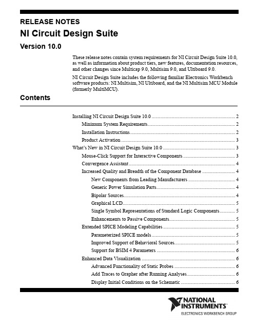
RELEASE NOTESNI Circuit Design SuiteVersion 10.0These release notes contain system requirements for NI Circuit Design Suite 10.0,as well as information about product tiers, new features, documentation resources,and other changes since Multicap 9.0, Multisim 9.0, and Ultiboard 9.0.NI Circuit Design Suite includes the following familiar Electronics Workbenchsoftware products: NI Multisim, NI Ultiboard, and the NI Multisim MCU Module(formerly MultiMCU).ContentsInstalling NI Circuit Design Suite 10.0 (2)Minimum System Requirements (2)Installation Instructions (2)Product Activation (3)What’s New in NI Circuit Design Suite 10.0 (3)Mouse-Click Support for Interactive Components (3)Convergence Assistant (4)Increased Quality and Breadth of the Component Database (4)New Components from Leading Manufacturers (4)Generic Power Simulation Parts (4)Bipolar Sources (4)Graphical LCD (5)Single Symbol Representations of Standard Logic Components (5)Enhancements to Passive Components (5)Extended SPICE Modeling Capabilities (5)Parameterized SPICE models (5)Improved Support of Behavioral Sources (5)Support for BSIM 4 Parameters (6)Enhanced Data Visualization (6)Advanced Functionality of Static Probes (6)Add Traces to Grapher after Running Analyses (6)Display Initial Conditions on the Schematic (6)Current Probe Instrument (6)Enhanced Analysis Capabilities (6)Extended Language Support and File Management in the MCU Module (7)Improvements to Speed and Quality of NI Ultiboard (7)Advanced Options for Exported Data Interpolation (7)Miscellaneous Features (8)Unicode Characters (8)NI Installation and License Management (8)Product Tier Details (8)Documentation (14)Installing NI Circuit Design Suite 10.0This section describes the system requirements and installation procedures forNI Circuit Design Suite.Minimum System RequirementsTo run NI Circuit Design Suite 10.0, National Instruments recommends that yoursystem meet the following requirements:•Windows 2000 Service Pack 3 or later, or Windows XP•Pentium 4 class microprocessor or equivalent (Pentium III class minimum)•512 MB of memory (256 MB minimum)• 1.5 GB of free hard disk space (1 GB minimum)•Open GL® capable 3D graphics card recommended (SVGA resolution videoadapter with 800×600 video resolution minimum, 1024×768 or higherpreferred)•To develop custom LabVIEW based instruments for use in Multisim,LabVIEW 8.0.x or higher is requiredInstallation InstructionsThe NI Circuit Design Suite 10.0 installer installs all products in the suite:Multisim, Ultiboard, and the Multisim MCU Module.National Instruments recommends that you close all open applications before youinstall NI Circuit Design Suite.Unless you specify another location during installation, the NI Circuit DesignSuite installation program copies files to <Program Files>\NationalNI Circuit Design Suite Release Instruments\Circuit Design Suite10.0 after you complete thefollowing steps:1.Insert the NI Circuit Design Suite CD into the CD-ROM drive. If the CDstartup screen is not visible, select Run from the Windows Start menu and runsetup.exe from your CD.2.Follow the instructions in the dialog boxes.Product ActivationWhen you run a product in the NI Circuit Design Suite for the first time, it willprompt you to activate a license for that product.Note: To run the Multisim MCU Module, place a component from the MCUModule group on a Multisim circuit or open a Multisim file that contains acomponent from the MCU Module group.If you do not activate a valid license, the product will run in Evaluation Mode andcontinue to prompt you to activate a license on each subsequent run. EvaluationMode is valid for 30 days following the first run of the product.For information about how to activate your software product, please refer to theActivation Instructions for National Instruments Products Note to Users includedwith your NI Circuit Design Suite 10.0 package.What’s New in NI Circuit Design Suite 10.0This document describes the following new features ofNI Circuit Design Suite 10.0:•Mouse-Click Support for Interactive Parts•Convergence Assistant•Increased Quality and Breadth of the Component Database•Extended SPICE Modeling Capabilities•Enhanced Data Visualization•Extended Analysis Capabilities•Extended Programming and File Management in the MCU Module•Improvements to Speed and Quality of NI Ultiboard•Advanced Options for Exported Data Interpolation•Miscellaneous FeaturesMouse-Click Support for Interactive ComponentsNI Multisim 10.0 lets you use your mouse to control interactive componentsduring simulation. You can click on switches to toggle them, push keypad buttonswith the mouse, and adjust the value of the variable components, such asNational Instruments Corporation3NI Circuit Design Suite Release Notespotentiometers, with a slider bar. You may also continue to use keyboard controlsfor these devices.Convergence AssistantThe Convergence Assistant adjusts simulation settings when a "Time Step TooSmall" error occurs during interactive simulation. The assistant adjusts theminimum number of parameters required in order to allow convergence of thesimulation. The assistant adjusts the following parameters:1.Initial Condition2.TMAX3.RELTOL4.RSHUNT5.ITL16.Integration method7.GMINIncreased Quality and Breadth of the Component DatabaseNI Multisim 10.0 has a number of new additions and improvements to thecomponent database. These include: around 1,000 new components from leadingmanufacturers, generic power simulation parts, new bipolar sources, a GraphicalLCD, single symbol representations of standard logic components, andimprovements to passive components.New Components from Leading ManufacturersNI Multisim 10.0 has approximately 1,000 new components with models fromAnalog Devices, Texas Instruments, and Linear Technologies. These additionsinclude symbols, models, and IPC-standard landpatterns. Components includeoperational-amplifier, comparator, and voltage reference models.Generic Power Simulation PartsNI Multisim 10.0 includes models for all power simulation parts found in the"Switch-Mode Power Supply SPICE Cookbook" by Christophe Basso. Thesecomponents include Buck, Boost, Buck-Boost, and PWM controllers. Theirmodels include voltage and current mode controlled devices, and models foraverage and detailed transient operation.Bipolar SourcesNew bipolar pulse sources include both current and voltage sources.NI Circuit Design Suite Release Graphical LCDA Graphical LCD is available for users who purchase the MCU Module inconjunction with NI Multisim. The command system for the Graphical LCDfollows the Toshiba T6963C. The graphical LCD is a two-color device with 256 x256 pixel display resolution. This device supports three modes of operation:text-only, graphics-only, and mixed text and graphics.Single Symbol Representations of Standard LogicComponentsIn addition to the multi-section component representation of standard logiccomponents such as logic gates and flip-flops, the component database nowincludes single symbol representations of common components. Thesesingle-symbol representations show the power and ground pins of these devices.Enhancements to Passive ComponentsYou can now change the value of any resistor, capacitor, or inductor placed on theschematic without replacing it. You can also assign a landpattern to any passivecomponent. You can assign information about the type of component, for instancemetal-oxide, and this information propagates to the Bill of Materials. Thetolerance of the components is automatically available for Monte-Carlo and WorstCase analyses, and you can edit the tolerances in the spreadsheet.An advanced non-linear inductor model lets you define the inductor characteristicsbased on datasheet values.Extended SPICE Modeling CapabilitiesNI Multisim 10.0 introduces enhancements to its SPICE modeling capabilities,including parameters in SPICE subcircuit models, improved support of behavioralsources, and support for BSIM 4 parameters.Parameterized SPICE modelsYou may now define parameters in the .subcircuit line of SPICE macro-models inNI Multisim. The definition of parameters is as follows..subckt<subckt_name><node_list>PARAMS:param_name=value,...You may then use the parameter name in place of a value in the macro-model. Thevalue of the parameter is editable in the component dialog on the schematic.Improved Support of Behavioral SourcesBehavioral sources now support nested instances of IF statements.National Instruments Corporation5NI Circuit Design Suite Release NotesSupport for BSIM 4 ParametersNI Multisim 10.0 supports the standard BSIM 4 parameters for MOSFET models.BSIM 4 supports up to 400 parameters. More information about BSIM 4 isavailable at /~bsim3/bsim4.html.Enhanced Data VisualizationNI Multisim 10.0 includes a number of improvements to the way you configureand view results. These include: advanced functionality of the static probes, theability to add traces to the Grapher after running a simulation, the ability to displaythe initial conditions of components on the schematic, a current probe instrument,and improvements to the memory and register displays of MCUs.Advanced Functionality of Static ProbesPlaced (static) probes now include a reference designator, which allows you toselect another probe as a reference net. In previous versions of NI Multisim, allprobes referenced ground. You can also use probe reference designators to selectwhich traces to view in analyses.Add Traces to Grapher after Running AnalysesYou can add traces to the Grapher view after running an analysis, and select whattype of data you want NI Multisim to store.Display Initial Conditions on the SchematicYou can choose to display the initial conditions of capacitors and inductors on theschematic.Current Probe InstrumentThe current probe instrument is a virtual representation of a real current probe thatconnects to an oscilloscope. You connect one end of the probe to a net on theschematic and the other to the input to an oscilloscope. You can set the ratio ofamps to volts displayed on the instrument. Note that the units remain in volts onthe oscilloscope.Enhanced Analysis CapabilitiesNI Multisim 10.0 now allows you to evaluate more expressions before and afterrunning analyses. The definitions of the expressions are:1.avg(X) — Running average of the vector X2.avg(X, d) — Running average of the vector X over dNI Circuit Design Suite Release 3.envmax(X, n) — Upper envelope of the vector X where n is the number ofpoints on either side of a peak that must be less than the value for a peak to beidentified4.envmin(X, n) — Lower envelope of the vector X where n is the number ofpoints on either side of a peak that must be less than the value for a peak to beidentified5.grpdelay(X) — Group delay of X with results in seconds6.rms(X) — Running RMS average of vector X7.integral(X) — Running integral of vector X8.sgn(X) — The sign or signum of a real number. It is -1 for a negative number,0 for the number zero, and 1 for a positive number.Extended Language Support and File Management in the MCU ModuleThe MCU Module, formerly MultiMCU, supports C-code in addition to Assemblylanguage. It has a code manager that lets you use multiple files to define theoperation of the microcontrollers in the design. You can have header files and uselibraries. You can also load in externally assembled binary files and view them indisassembled format.Improvements to Speed and Quality of NI UltiboardNI Ultiboard 10.0 contains enhancements to the quality of the product that includeimprovements to the speed of trace-placment and the ability to select whether ornot to plate through-holes. Exported Gerber files do not contain mosaics in thepolygons. Quality improvements in the landpatterns include: pin mappings fromsymbols to IC pin-outs and landpattern shapes and sizes in the database. All newlandpatterns follow IPC standards.Advanced Options for Exported Data InterpolationWhen exporting simulation data from NI Multisim to other NI data formats suchas LVM or TDM files, you can choose the interpolation technique that best suitsthe signal. You can also control the interpolation method used when sendingsimulation data to NI LabVIEW based instruments running inside of NI Multisim.The interpolation methods include:•Coerce•Linear Interpolation•Spline InterpolationNational Instruments Corporation7NI Circuit Design Suite Release NotesMiscellaneous FeaturesSome of the other features added to the new suite include Unicode charactersupport and NI installation and license management.Unicode CharactersAll products in NI Circuit Design Suite 10.0 support Unicode characters. Thisfeature allows you to use Cyrillic and Asian fonts inside the products.NI Installation and License ManagementAll products in NI Circuit Design Suite adhere to the standard method used toinstall and activate National Instruments software. You can activate the softwareautomatically via the internet, or manually via a web browser, phone call, oremail.Product Tier DetailsThe following lists the schematic capture functionality available in MultisimStudent and Education editions:Functionality Student EducationCustomizable GUI X XScreen-capture utility X XComments on schematic X XCircuit annotations X XModeless part placement and wiring X XFast retrieval parts bins X XAuto and manual wiring X XVirtual wiring by node name X XRubber banding on part move X XFast auto-connect passives X XSubcircuits X X3-dimensional breadboarding X XVirtual NI ELVIS X XEmbedded questions - view and respond X XNI Circuit Design Suite Release Functionality Student EducationForward/Back annotation with Ultiboard X XCross-probing with Ultiboard X XBus-vector connect XSpreadsheet view XDesign constraints for layout XAdvanced search XZoom to selected part XCorporate database XUser defined fields XXSave components to database fromworkspaceMultiple circuits open XEmbedded questions - create and edit XElectrical rules check XGraphically mark no-connect pins XHierarchical designs XMultisheet designs XProject manager XReports - including bill of materials XPin and gate swap XExport to Mentor PADS layout XDevice library Partial CompleteMaximum components in design50UnlimitedNational Instruments Corporation9NI Circuit Design Suite Release NotesThe following lists the simulation functionality available in Multisim Student andEducation editions:Functionality Student EducationInteractive simulation X XFully mixed-mode A/D simulation X XStandard SPICE 3X5/XSPICE X XEnhanced model support X XPSPICE model simulation* X XSpeed/Accuracy tradeoffs X XSimulation advisor X XConvergence assistant X XVirtual, interactive, animated parts X XMouse click support for interactive parts X XRated components X XInsert faults into components X XMeasurement Probes X XComponent Wizard X XNI measurement data file sources X XNI measurement data file export X XX XNI LabVIEW VIs as instruments andsourcesMicrophone & speaker X XCircuit restrictions X XGrapher & Postprocessor X XRF design kit X XCircuit wizards XC-Code modeling XDescription box synced with simulation XLadder diagrams/components XModel makers XNI Circuit Design Suite Release Load and save simulation profiles XVirtual Instruments 2222Analyses1018Co-simulation of MCUs Add On Add On* Does not support all PSpice syntaxThe following lists the layout functionality available in Ultiboard Student andEducation editions:Functionality Student EducationPush and Shove trace placement X XReal-time & from copper ratsnest X XReal-time polygon update with voiding X XForward/Backward annotation X XCross-probing with Multisim X XReal-time DRC X X64 layers and 1 nanometer resolution X XComprehensive Footprint Wizard X XEnhanced 3D visualization with print X XUser annotations X XFull screen mode XGerber, DXF, IPC-D-356A, SVG output XDimensions on PCB and Landpatterns XDimensions in Database Manager XNet bridges X3D visualization inside circuit board XTurn off ratsnest for selected nets XGridless follow-me placement XLoad and save technology files XPolar Grids XNational Instruments Corporation11NI Circuit Design Suite Release NotesCustomizable layer viewing XSplit power-planes XKeep-in/Keep-out areas XPlace components in array XUnplace all components XRuler bar alignments and measurements XAuto-alignment XSave PCB Design as a component XPermanent grouping XPin & gate swapping XMultiple clearances XJump to Error XEquispace trace support XDifferential Impedance Calculator XTransmission Line Calculator XMicrovias XTest point insertion XAutomatic tear-dropping XPin necked trace support XAutomatic jumper insertion XCopy Route & Replica Place functions XIn-place footprint editor XMechanical CAD XExport 3D info in 3D IGES, DXF formats XCopper amount report XTest point report XCustomization of report generation XMultiple open documents XNI Circuit Design Suite Release National Instruments Corporation 13NI Circuit Design Suite Release NotesThe following lists the autorouting functionality available in Ultiboard Student and Education editions:Number of pins supported 3501,000Spreadsheet viewLimitedCompleteFunctionalityStudentEducationFully customizable cost factors X X Progressive Routing X X Interactive autorouting X X Constraint driven routingX X Manual pre-placement: components, vias, tracesX X Auto Block Capacitor recognition X X SMD mirroring X X Trace rubberbandingX X Follows keep-in/keep-out criteria X X Pin number limit3501,000Maximum number of layers24DocumentationNI Circuit Design Suite 10.0 includes a complete documentation set featuringprinted and electronic resources for your reference.The following printed and electronic resource is available:•Getting Started with NI Circuit Design Suite GuideThe following electronic resources are available in PDF files:•Multisim User Guide•Multisim Component Reference Guide•Multisim for Educators Guide•Multisim MCU Module User Guide•Ultiboard User GuideTo access the User Guides, select Start > All Programs > National Instruments >Circuit Design Suite 10.0 > Documentation and then select the file of interest.The following online help files are available from the installed software Helpmenu and from the Start Menu:•Multisim Education Edition Help File•Ultiboard Help FileTo access the Help Files, select Start > All Programs > National Instruments >Circuit Design Suite 10.0 > Documentation and then select the file of interest.The following online help files are available from the installed software Helpmenu:•Component Reference Education Edition Help File•Multisim Symbol Editor Help File•Multisim Title Block Editor Help FileNI Circuit Design Suite Release National Instruments, NI, , and LabVIEW are trademarks of National Instruments Corporation.Refer to the Terms of Use section on /legal for more information about National Instrumentstrademarks. Ultiboard is a registered trademark and Multisim and Electronics Workbench aretrademarks of Electronics Workbench. Other product and company names mentioned herein aretrademarks or trade names of their respective companies.374480A-01 Jan07© 2007 National Instruments Corp. All rights reserved.。
龙芯 1B 开发学习套件 用户手册说明书

1、电源和开关 ..............................................................................................................................7 2、ADC和DAC .................................................................................................................................7 3、串口和 485...............................................................................................................................8 4、Debug调试接口 .......................................................................................................................8 5、CAN接口....................................................................................................................................8 6、DC插座 ......................................................................................................................................9 7、LCD 接口................................................................................................................................10 第二章 LoongIDE集成开发环境 ...............................................................................................................11 第一节 系统安装 ................................................................................................................................11 1、运行环境 ................................................................................................................................11 2、LoongIDE安装.......................................................................................................................11 3、GNU 工具链............................................................................................................................12 4、注意事项 ................................................................................................................................13 第二节 串口控制台 ............................................................................................................................13 第三节 常见问题 ................................................................................................................................14 1、LxLink驱动安装 ...................................................................................................................14 2、引导程序PMON........................................................................................................................15 第四节 编程前准备 ............................................................................................................................16 1、设置默认工作区 ....................................................................................................................16 2、工具链配置 ............................................................................................................................16 3、主机IP地址 ............................................................................................................................17 第三章 设备驱动与编程参考.....................................................................................................................18 第一节 创建项目框架.........................................................................................................................18 1、项目向导 ................................................................................................................................18 2、项目目录与文件 ....................................................................................................................19 第二节 配置BSP..................................................................................................................................20 1、片上设备使用列表 ................................................................................................................20 2、SPI0 总线上的从设备...........................................................................................................21
欧倍尔增强复合材料虚拟仿真实验说明书

不饱和聚酯树脂的合成及玻璃纤维增强复合材料虚拟仿真实验说明书北京欧倍尔软件技术开发有限公司2018年6月地址:北京市海淀区清河永泰园甲1号建金商厦420-423室 邮编:100193目 录第一章 软件简介 (1)1.1 概述 .................................................................................................................................... 1 1.2 软件特色 ............................................................................................................................ 1 第二章 软件安装 ............................................................................................................................. 2 第三章 软件操作说明 (2)3.1 软件启动 ............................................................................................................................ 2 3.2功能介绍 ............................................................................................................................. 3 3.3界面介绍 .. (4)3.3.1菜单功能条 ............................................................................................................ 4 3.3.2仓库功能条 ............................................................................................................ 5 3.3.3操作指导栏 ............................................................................................................ 5 3.3.4评分界面 ................................................................................................................ 6 3.4 实验操作 . (6)3.4.1实验准备及装置搭建 ............................................................................................ 6 3.4.2不饱和聚酯树脂的合成 ........................................................................................ 9 3.4.3加固化剂配料 ...................................................................................................... 10 3.4.4玻纤增强复合材料的制备 . (11)第四章 注意事项 (13)4.1 软件运行注意事项及常见问题 (13)4.1.1 软件运行注意事项 ............................................................................................. 13 4.1.2 其中容易被杀毒软件阻止的程序 ..................................................................... 14 4.2安装过程中常见问题 . (15)4.2.1 控件注册失败 (15)第一章软件简介1.1 概述本软件是基础化学学科教育信息化建设项目,旨在为本科院校化工相关专业的学生提供一个三维的、高仿真度的、高交互操作的、全程参与式的、可提供实时信息反馈与操作指导的、虚拟的基础化学模拟操作平台,使学生通过在本平台上的操作练习,进一步熟悉专业基础知识、了解化学实验室实际实验环境、培训基本动手能力,为进行实际实验奠定良好基础。
STpad 工业4.0智能连接质量检查平台说明书

IRC-Connect Bluetooth8059 095 681The STa 6000 device con-nected to QA Supervisor provides a wide range of addi-tional traceability and reporting features to the data analyzer.There is a dedicated license for the installation of STa 6000 thatallows to perform tool check operations with the STa 6000 only for a simple and effective tools maintenance.QA Supervisor is the new inno-vative software for the complete process management.It fully manages the tool, joint and visual check processes in any detailQA Supervisor is a server based software that makes it easy for the quality manager to access from any web browser to control the status of the tests of the com-plete line from any location.In fact every single detail of the plant structure can be defined into QA Supervisor, from the li-nes definition to the station set up including production tighte-ning specification, from the list of each tool used in every location to the characteristics of the speci-fic bolt type that is tighten in any application.QA Supervisor keeps track of every change that happens in the line setup, this makes any audit quick and effective as data are clearly and historically presented. QA Supervisor features the latest technology for Quality software with powerful and user friendly functionalities, it represents the natural complement of every Quality Assurance testing setup as it helps, controlling and mo-nitoring the process, to prevent quality issues in the production line.Tool Check feature 8059098230Joint Check feature 8059098231Visual Check feature 80590982331 measurement device 80590982385 measurement devices 805909823910 measurement devices 8059098240QA Supervisor JSB client8059098250QUALITY PROCESS PLANNING AND MONITORINGFULL PROCESS TRACEABILITY INNOVATIVE INTERFACEWEB BROWSER BASED。
- 1、下载文档前请自行甄别文档内容的完整性,平台不提供额外的编辑、内容补充、找答案等附加服务。
- 2、"仅部分预览"的文档,不可在线预览部分如存在完整性等问题,可反馈申请退款(可完整预览的文档不适用该条件!)。
- 3、如文档侵犯您的权益,请联系客服反馈,我们会尽快为您处理(人工客服工作时间:9:00-18:30)。
CST MS | 协同仿真 1
Faq-100401: 建立PCBS/CS和MS之间的协同仿真
PCBS(CST 印制板工作室™)/CS(CST 电缆工作室™)文件导出I/V分布文件可以直接导入到CST MS中进行三维仿真
分析,这里以CST印制板工作室™为例。
1) 在CST 印制板工作室™里设置仿真方案。
仿真后,在相应的文件夹中找到rad,tbs,ths,xvs四个文件,
2) 在MS的安装目录中找到Simlab2EsfTranslator.exe,并双击运行。
点击浏览器按钮,分别选择印制板工作室™生成的*.ths\*.xvs\*.tbs\*.rad四个文件,Translator将根据这四个文
件生成MS仿真需要的Compact Source: *.esf。
2 CST工作室套装™–常见问题解答FAQs
选好*.ths\*.xvs\*.tbs\*.rad四个文件后,为MS的Compact Source指定一个路径和名字,这里我们将它命名为cst_Ms。
点击Translate按钮即可生成我们需要的cst_Ms.esf文件
cst_Ms.esf文件生成结束后,点击Close按钮关闭对话框即可。
进入到MS在EM Properties页面下选择Excitations按钮
在Excitations对话框中点击Create…按钮,打开下拉列表,在下拉列表中选择Compact source打开Compact source对话框
CST MS | 协同仿真 3
点击Browse…按钮,打开浏览器选择需要的激励源:cst_Ms.esf
设置好激励源的参数后,点击OK按钮关闭Compact source对话框,回到Excitations对话框。
点击Excitations
对话框的Close按钮关闭该对话框即可在启动MS的TLM求解器进行仿真分析。