Ansys 12.0 CFX 官方教程 11B
Ansys CFX 专业教程

ANSYS, Inc. Proprietary © 2009 ANSYS, Inc. All rights reserved.
B-2
April 28, 2009 Inventory #002598
Turbo Pre and Post
CFX-Pre Turbo Mode
Training Manual
3. Physics Definition – Fluid properties – Steady State vs. Transient – Model Data
• Energy and Turbulence Models
– Boundary Templates:
• Pt inlet - Ps outlet • Pt inlet - mass flow outlet • Mass flow inlet – Ps outlet
• Turbo mode in ANSYS CFX-Pre is a specialist mode allowing users to set up turbo machinery simulations, such as compressors or turbines, in a simple manner.
– Interface Type:
• Stage, Frozen Rotor, Transient Rotor Stator
– Solver parameters
• Advection Scheme • Time Scale/Step controls
ANSYS, Inc. Proprietary © 2009 ANSYS, Inc. All rights reserved.
• Frozen rotor • Transient rotor stator • Stage • Periodic • None
ANSYS12.0安装方法
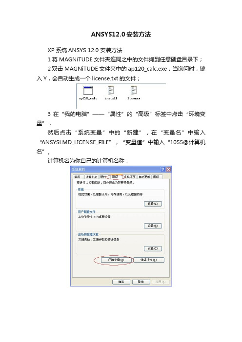
ANSYS12.0安装方法XP系统ANSYS 12.0 安装方法1将MAGNiTUDE文件夹连同之中的文件拷到任意硬盘目录下;2 双击MAGNiTUDE文件夹中的ap120_calc.exe,当询问时,键入Y,会自动生成一个license.txt的文件;3 在“我的电脑”——“属性”的“高级”标签中点击“环境变量”,然后点击“系统变量”中的“新建”,在“变量名”中输入“ANSYSLMD_LICENSE_FILE”,“变量值”中输入“1055@计算机名”。
计算机名为你自己的计算机名称;4 运行安装主程序,点击setup.exe5 弹出安装菜单如上图,按照从上至下的顺序,先点击第一个按钮,开始进行必要的一些程序需求安装;依次点击OK,当安装NET Framework 2.0 SP1时,如果出现显示“安装程序错误”,则直接取消安装,安装将会跳出;6 继续安装,点击Install ANSYS,Inc.Products,A 进行安装时,第一步骤会显示一个英文框,下面左下面点击“I AGREE”,然后点击NEXTB 继续点击NEXT,弹出如下窗口,Mount Directory不需要更改系统自动添加,更改貌似会出现错误,一般不更改,可以根据自己的习惯将Install Directory 更改目录;C点击Next,会显示下图,根据自己需要选择是否安装PRO/E和UG的相关组件,D 点击Next继续安装,会有Enter the Pro/ENGINEER information 如果你没有选择这些就点击下面的两个Skip,直接跳过E 点击Next继续安装,会有Enter the Unigraphics NX information也直接跳过,F后面直接Next继续安装,将进行主程序的安装,开始安装,需要解压100个安装包,后面会有一个13项相关程序的安装,当然这些都不需要我们进行操作,G 安装好后,出现需要手动操作的点击Next,系统会进行自动检测,然后进入设置界面,会弹出一个窗口,在第一个Hostname中输入你自己的计算机名,点击OK,程序根据进行自动配置,完成后退出;H 完成主程序的安装;7 回到初始点击Setup时的窗口,进行License manger的安装,第一步仍然是点击“I AGREE”,然后依次点击Next,直到开始安装许可证,窗口下方会有三个RUN 选择第一个RUN 点击Continue,继续点击Continue会弹出对话框,在这里将开始安装之前已经生成的license文件复制到C:\Program Files\ANSYS Inc中,复制好后,选择此文件,继续点击Continue,直到弹出初始点击Setup时的窗口,退出安装;至此完成了ANSYS 12.0的安装,8 点击开始——所有程序——ANSYS 12.0——Mechanical APDL Product Launcher。
ANSYS12.0安装教程(详细)
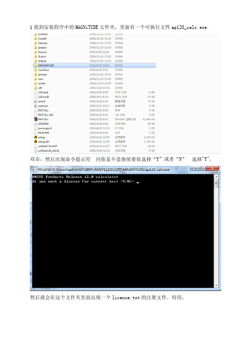
1找到安装程序中的MAGNiTUDE文件夹,里面有一个可执行文件ap120_calc.exe双击,Y”或者“N"Y",然后就会在这个文件夹里面出现一个license.txt的注册文件。
待用。
2、双击文件夹中setup.exe.出现一个对话框。
3、点击install requried prerequisites,先装一些微软的支持软件,全部都安装。
4、点击第2步出现的对话框的第二个按钮,即install ansys.inc products。
点击Next5.点击Next,Install Directory选择安装目录,Mount Directory为源程序所在目录。
6.是否选择使用CAD(ProE、NX)软件接口第一个是ProE的点击Next7.是否使用NX接口8.点击Next9.点击Next,需要十几分钟时间安装10.完成后,需要输入计算机完整名称,计算机名称,右键点击“我的电脑”查看“属性“点击“计算机名”里面有个完整的计算机名。
点击“OK”点击Next,选择默认就可以会弹出浏览器窗口,关闭就可以。
点击Finish,完成。
★▲如果在安装install ansys.inc products过程中没有提示安装许可证,此时将第一步生成的license.txt,文件复制到安装目录下。
▲license.txt复制到C:/program files/ansys inc下即可我在安装时没要求安装许可证,不做详细说明。
11.点击第2步出现的对话框的第三个按钮,安装License Manager。
注意路径需修改。
点击“OK”,选择“I AGREE”点击Next点击Next,等待几分钟安装。
完成后,选择“Continue”12.选择“Continue”,在选择license文件之前,将第一步的license文件复制到安装目录下13.然后选择license文件,打开继续“Continue”完成后,退出。
ANSYS12.0的安装破解
ANSYS12.0的安装破解ANSYS12.0的安装破解说明:本方法适用于XP及WIN732位系统。
首先使用虚拟光驱软件挂载ANSYS12.0的安装光盘,运行其中的setup,我们选择第二项,安装ANSYS产品(如果一些基本的运行库没有的话,需要先选择第一项进行安装,这里默认你已经有这些库了)出现协议,同意即可。
选择安装平台,直接选择默认就可以。
这里需要选择安装的位置,选择一下就可以。
这里需要选择安装的细节,选择你需要的安装项目,如果不清楚,就保持默认即可。
这里选择已安装的PRO/E的安装位置,如果你不知道这是啥,或者没有安装PRO/E,就像我一样把下面两个SKIP选择了就可以。
还是一样,如果你不知道或者木有安装就SKIP掉。
一个自动的确认过程,直接NEXT掉就可以。
接下来是配置的详情,确认就可以。
100个包的安装过程,慢慢等吧,会比较慢,可以去社交网站看看女神的最新动态,或者上QQ和女神聊聊天,小心被呵呵~ 安装配置了半天,终于结束了。
点击NEXT继续。
接下来是认证客户端的配置,需要我们修改的是主机的名称。
如果不知道的话,可以在我的电脑上点击右键查看。
之后直接确定就好。
之后会出现配置的Log记录,EXIT退出。
提示安装成功,NEXT继续。
接下来是选择你IE的所在位置,便于让你访问ANSYS的网站,我们选择FINISH就可以直接完成而不必打开浏览器了。
接下来是证书管理的安装,我们选择第三个。
这里会给出提示,如果正在运行证书服务,需要关闭,如果是首次安装ANSYS就不必管,直接OK就可以了。
依旧是协议,接受吧~还是选择安装平台,我们NEXT必须安装到系统盘,那就直接NEXT选择安装组件,直接默认就可以了。
还是一个自动的验证阶段,直接NEXT确认一下,直接NEXT就好这次比较快,只有三个包安装之后就NEXT继续验证服务的一个自动配置过程,等会儿就好了。
这里我们选择默认就可以点击两次continue,需要让你选择注册文件。
ANSYS12.0官方培训教程W...
Workshop 2.1ANSYS Mechanical BasicsWorkshop Supplement •The first workshop is extensively documented. As this course progresses, students will become more familiar with basic Workbench Mechanical functionality (menu locations etc.), thus subsequent workshops will contain less details.•Throughout these workshops menu paths are documented as: “First pick > Second pick > etc.”.•Workshops begin with a goals section followed by an assumptions section.Workshop Supplement •Using the Stress Wizard, set up and solvea structural model for stress, deflectionand safety factor.•Problem statement:–The model consists of a Parasolid filerepresenting a control box cover (seefigure). The cover is intended to be used inan external pressure application (1 Mpa/145psi).–The cover is to be made from aluminumalloy.–Our goal is to verify that the part willfunction in its intended environment.Workshop Supplement •We will represent the constrains onthe counter bores, bottom contactarea and inner sides using frictionlesssupports.–Frictionless supports place a normalconstraint on an entire surface.Translational displacement is allowedin all directions except into and out ofthe supported plane. Since we wouldexpect frictional forces to at contactareas this is a conservative approach.Workshop Supplement •Loads: the load consists of a 1 MPa pressure applied to the 17 exterior surfaces of the cover.Workshop Supplement •Open the Project page.•From the “Units” menu verify:–Project units are set to “US Customary (lbm, in, s, F, A, lbf, V).–“Display Values in Project Units” is checked (on).Workshop Supplement1.From the Toolbox choosecreate a Static Structuralsystem (drag/drop or RMB).2.RMB in the Geometry cell andImport Geometry. Browse tothe file “Cap_fillets.x_t”.Workshop Supplement3.Double click the “Model” cell to open theMechanical application.4.When the Mechanical application opens themodel will display in the graphics window andthe Mechanical Application Wizard displayson the right.When Mechanicalstarts if the Wizardis not displayed,use the icon toopen it.Workshop Supplement5.Set the units system:•From the main menu go to “Units > Metric (mm,kg, N, s, mV, mA).Workshop Supplement6.Select a suitable material for the part:a.From the Mechanical Wizard choose “Verify Material”b.Notice the callout box indicates Engineering Data isaccessible from the WB2 interface (Project Schematic).c.Return to the Project schematic window and double click“Engineering Data” to access the material properties.Workshop Supplement7.With General Materialshighlighted click the ‘+’ next to“Aluminum Allow” to add thismaterial to the current project.8.Return to the Project.•Notice the Model cell indicates arefresh is necessary.9.Refresh the Model cell (RMB),then return to the Mechanicalwindow.Workshop Supplement 10.Highlight “Part 1” and click the“Material > Assignment” field tochange the material property toaluminum alloy.Workshop Supplement11.Insert Loads:a.Select “Insert Structural Loads ” from the Wizardb.Follow the call out box to insert a “Pressure ” loadc.The tree will now include a Pressure load in the “Static Structural ”environment branchc.Workshop Supplement12.Apply the load to geometry:a)Highlight one of the outer faces of the part.b)Use the “Extend to Limits” icon to select the remaining 16 faces (total 17 facesselected).c)Click “Apply” to accept the faces.d)Enter a “Magnitude”of 1MPa.a.b.Workshop Supplement 13. Apply supports to constrain the part:a.Select “Insert Supports” from the Wizard.b.Follow the callout box to insert a “Frictionless Support”.c.“Apply”it to the 4 counter bore surfaces of the part.b.Workshop Supplement14.Repeat Steps 13.a. and 13.b. to insert a“Frictionless Support” on the inner surfacesof the bottom recess (use extend to limitsafter selecting one of the inner surfaces.15.Repeat Steps 13.a. and 13.b. to insert a“Frictionless Support” on the lip surface atthe bottom of the recess.Workshop Supplement16.From the Mechanical Wizard request:a)Insert Structural Results (the call out will point to the Solution toolbar).b)Deformation > Total.c)Stress > Equivalent (von-Mises).d)Tools > Stress Tool.Note the Stress Tool detail allows 4 different configurations (explained later). For this workshop we will leave the tool specified as “Max Equivalent Stress ”theory.Workshop Supplement17.Solve the model:a.Select “Solve” from the Wizard.b.Follow the callout box and click on “Solve”.•Note how clicking on “Solve” in the Wizard does not automatically start solving the model but instead, points out the “Solve” icon to the user. Alternatively, you could right click on any branch in the “outline” and choose “Solve”a.b.Workshop Supplement18.View the results:a.Click “View Results ” from the Wizardb.Follow the callout box to where the results are available under the “Solution ”branchb.Workshop Supplement •Plotting a model’s deformation often provides a “reality check” in structural analysis. Verifying the general nature (direction and amount) of deflection can help avoid obvious mistakes in model setup. Animations are often used as well.Workshop Supplement •After reviewing stress results expand the safety tool and plot safety factor. Notice the failure theory selected predicts a minimum safety factor of just over 1.Workshop Supplement 19.Create an html report:a.First choose the graphical items you wishto include in your report by highlighting thebranches and orienting the plot (this is yourchoice).b.Next, insert a “Figure ” from the toolbar.c.Click the “Report Preview ” tab to generatethe report.c.Workshop SupplementNotes on Figures:•Figures are not limited to results items. Adding a plot of the environment branch, for example, will include an image of model boundary conditions in the Report.•Figures are independent. You may set up individual figures and have their orientation, zoom level, etc. retained regardless of the active model orientation or other figures.•Individual branches can have multiple figures associated with them.。
Ansys_12.0_CFX_官方教程__12
Rotating domain
Single Component (blower wheel blade passage)
Multiple Component (blower wheel + casing)
x
Domain
Mesh Deformation – Domain changes shape as a function of time
ANSYS, Inc. Proprietary 2009 ANSYS, Inc. All rights reserved.
12-5
April 28, 2009 Inventory #002598
Topics Domain Motion
– Rotating Fluid Domains
Single Frame of Reference Multiple Frames of Reference
– Frame Change Models – Pitch Change
Training Manual
Moving Zones
Rotating Reference Frames Why use a rotating reference frame?
Training Manual
– Flow field which is unsteady when viewed in a stationary frame can become steady when viewed in a rotating frame – Steady-state problems are easier to solve...
Ansys_12.0_CFX_官方教程
B-5
April 28, 2009 Inventory #002598
Turbo Pre and Post
CFX-Pre Turbo Mode 2. Component Definition – Import meshes (right-click) – Define rotating or stationary
Turbo Pre and Post
CFD-Post Turbo Workspace
Training Manual
• The Turbo workspace:
– Creates span, m’, axial, radial and theta coordinate frames – Allows users to visualize components in turbo space – One-button calculation of velocity components (such as circumferential, radial, axial, meridional) – Quickly generate turbo related charts and graphs – Provides access to turbo specific macros
Appendix B Turbo Pre and Post
Introduction to CFX
ANSYS, Inc. Proprietary © 2009 ANSYS, Inc. All rights reserved.
B-1
April 28, 2009 Inventory #002598
Turbo Pre
• Stage, Frozen Rotor, Transient Rotor Stator
ansys学习教程
ANSYS学习教程简介ANSYS是一种强大的有限元分析软件,广泛应用于工程领域。
它具有丰富的功能和强大的求解能力,可以模拟各种复杂的物理现象和工程问题。
本教程将介绍ANSYS的基本知识和使用方法,帮助初学者快速入门。
安装与配置ANSYS的安装过程比较简单,用户只需按照官方说明进行下载和安装即可。
安装完成后,需要进行一些基本的配置,以确保软件的正常运行。
这些配置包括设置工作目录、导入所需的模块和插件等。
设置工作目录在使用ANSYS之前,首先需要设置一个工作目录,用于存储工程文件和计算结果。
用户可以选择一个合适的目录,然后在ANSYS的设置中进行配置。
导入模块和插件ANSYS提供了多个模块和插件,用于不同类型的工程分析。
用户可以根据自己的需求选择相应的模块和插件,并将其导入到ANSYS中。
导入完成后,这些模块和插件将在软件中显示为可用的功能。
建模和网格生成在进行工程分析之前,需要先进行建模和网格生成。
建模就是根据实际物理对象创建虚拟模型,网格生成则是将模型划分为小的单元,以便进行数值计算。
几何建模几何建模是将物理对象抽象为几何图形的过程。
ANSYS提供了多种建模工具,包括实体建模和面建模。
用户可以使用这些工具创建复杂的几何模型,并添加相应的约束和条件。
网格生成网格生成是将几何模型划分为小的单元的过程。
ANSYS提供了多种网格生成算法,包括结构化网格和非结构化网格。
用户可以选择合适的算法,并进行参数设置,以获得高质量的网格。
边界条件和加载在进行工程分析之前,需要确定边界条件和加载。
边界条件是对系统边界的约束,加载是对系统施加的外界力或位移。
边界条件边界条件包括固支约束、自由度约束和热边界条件等。
用户需要根据具体情况设置适当的边界条件,以准确模拟实际工程问题。
加载加载是对系统施加的外界力或位移。
ANSYS提供了多种加载方式,包括点力、面力、压力和位移等。
用户可以根据实际需求设置加载方式和加载大小。
求解和后处理求解和后处理是ANSYS的核心功能之一。
- 1、下载文档前请自行甄别文档内容的完整性,平台不提供额外的编辑、内容补充、找答案等附加服务。
- 2、"仅部分预览"的文档,不可在线预览部分如存在完整性等问题,可反馈申请退款(可完整预览的文档不适用该条件!)。
- 3、如文档侵犯您的权益,请联系客服反馈,我们会尽快为您处理(人工客服工作时间:9:00-18:30)。
The syntax rules are the same as those for conventional arithmetic. Operators are written as: + (addition) - (subtraction) * (multiplication) / (division) ^ (exponentiation) Variables and expressions are case sensitive (example: t vs. T) Expressions must be dimensionally consistent for addition and subtraction operations (example: 1.0 [mm] + 0.45 [yds] is OK)
Chapter 11 CFX Expression Language (CEL)
Introduction to CFX
ANSYS, Inc. Proprietary 2009 ANSYS, Inc. All rights reserved.
11-1
April 28, 2009 Inventory #002598
11-5
Depending on your physics, some variables will not be valid – e.g. you need to solver heat transfer to use T
April 28, 2009 Inventory #002598
CFX Expression Language
Example:
ANSYS, Inc. Proprietary 2009 ANSYS, Inc. All rights reserved.
11-2
April 28, 2009 Inventory #002598
CFX Expression Language
CEL Rules
Training Manual
Function sin(x) cos(x) tan(x) *** asin(x) acos(x) atan(x) exp(x) loge(x) log10(x) abs(x) sqrt(x) if(test, res1, res2)* min(x,y) **** max(x,y) **** step(x) * Operand’s Dimensions [x] Angle Angle Angle Dimensionless Dimensionless Dimensionless Dimensionless Dimensionless Dimensionless Any Any Any Any Any Dimensionless Operand’s Values Any Any Any -1 ≤ x ≤ 1 -1 ≤ x ≤ 1 Any Any 0<x 0<x Any 0≤x Any Any Any Any
Training Manual
Numerical functions and operators are also available in CEL
Result’s Dimensions Dimensionless Dimensionless Dimensionless Angle Angle Angle Dimensionless Dimensionless Dimensionless [x] [x]^0.5 Any (res1 and res2 must have the same dimensions) [x] [x] Dimensionless
How To Create Expressions
Training Manual
ANSYS, Inc. Proprietary 2009 ANSYS, Inc. All rights reserved.
11-6
April 28, 2009 Inventory #002598
CFX Expression Language
– – – – e g pi R Constant: 2.7182818 Acceleration due to gravity: 9.806 [m s^-2] Constant: 3.1415927 Universal Gas Constant: 8314.5 [m^2 s^-2 K^-1]
11-3
*if functions contain a test, and two result outcomes. The first outcome, res1 will be returned if test evaluates to true. If test evaluates to false, res2 is returned. Consider the following example, where we wish to set volume fraction to 1 when X is greater than 1 [m], and 0 if X is less than 1 [m]: if (x>1[m], 1, 0) In this case, if the result is precisely equal to 1[m], the result is (res1+res2)/2 **step(x) is 0 for negative x, 1 for positive x and 0.5 for x=0. *** note that tan(x) is undefined for nπ/2 where n=1, 3, 5 .. . **** both x and y must have the same dimensions.
– You cannot add values with inconsistent dimensions
Fractional and decimal powers are allowed (example: a^(1/2) + 1.0^0.5) Units of expressions are not declared – they are the result of units in the expression (example: a [kg m^-3] * b [m s^-1] has units of [kg m^-2 s^-1] Some constants are also available in CEL for use in expressions:
How To Create Expressions
Training Manual
To add more expressions (similar method in CFD-Post)
Right-click in the Definition ow to access Variables, Constants, Functions, Locators and existing Expressions
ANSYS, Inc. Proprietary 2009 ANSYS, Inc. All rights reserved. April 28, 2009 Inventory #002598
11-4
CFX Expression Language
Solver Variables
Solver variables are available for use in any expression Below is a partial list of the available system variables:
ANSYS, Inc. Proprietary 2009 ANSYS, Inc. All rights reserved.
11-7
April 28, 2009 Inventory #002598
CFX Expression Language
CEL in CFX-Pre: Example 1
Creating a variable viscosity – Viscosity of a shear thickening fluid:
Training Manual
= Kγ n1
where γ is the shear strain rate
Solver Variable and Expression Name are both accessed via the right mouse button
ANSYS, Inc. Proprietary 2009 ANSYS, Inc. All rights reserved.
– When creating expressions, right-click to access a full list
x y z r theta t u v w p ke ed T sstrnr density rNoDim viscosity Cp cond AV name mf
ANSYS, Inc. Proprietary 2009 ANSYS, Inc. All rights reserved.
CFX Expression Language
CEL
CEL - CFX Expression Language
Training Manual
– Allows the user to create equations (can be functions of solution/system variables) that can be used in CFX-Pre and CFD-Post
11-8
April 28, 2009 Inventory #002598
CFX Expression Language
CEL in CFX-Pre: Example 1