Technical Guide of Electrical Double Layer Capacitor
电气设计技术标准英语

电气设计技术标准英语Electrical design is an essential process in various industries, including power generation, manufacturing, construction, and telecommunications. It involves the creation of detailed plans, specifications, and drawings for electrical systems and equipment. To ensure efficiency, safety, and compatibility, a set of technical standards must be established and followed in the electrical design process. These standards help ensure that electrical systems are designed, installed, and operated in a consistent and reliable manner. In this article, we will provide a reference list of commonly used electrical design technical standards and their key contents.1. National Electrical Code (NEC) - The NEC is a comprehensive set of standards governing electrical installations in the United States. It covers topics such as electrical wiring, grounding, overcurrent protection, and electrical equipment specifications. The NEC is regularly updated to address emerging technologies and safety concerns.2. International Electrotechnical Commission (IEC) Standards - The IEC is a global organization that develops and publishes international standards for the electrical industry. Some of the key IEC standards relevant to electrical design include IEC 60038 (Standard Voltages), IEC 60204 (Safety of Machinery - Electrical Equipment of Machines), and IEC 61346 (Industrial Systems, Installations, and Equipment and Industrial Products - Structuring Principles and Reference Designations).3. Institute of Electrical and Electronics Engineers (IEEE)Standards - The IEEE is a renowned professional organization that develops standards for various fields related to electrical engineering. In the context of electrical design, the IEEE 141 standard (Recommended Practice for Electric Power Distribution for Industrial Plants) and the IEEE 399 standard (Recommended Practice for Industrial and Commercial Power Systems Analysis) are widely referenced.4. American National Standards Institute (ANSI) Standards - ANSI works to develop and promote voluntary consensus-based standards in the United States. ANSI standards that are often applied in electrical design include ANSI/NETA MTS (Maintenance Testing Specifications for Electrical Power Equipment and Systems) and ANSI/NETA ATS (Acceptance Testing Specifications for Electrical Power Equipment and Systems).5. International Organization for Standardization (ISO) Standards - ISO develops international standards in various industries, including electrical engineering. ISO/IEC 27001:2013 (Information technology - Security techniques - Information security management systems - Requirements) is an example of an ISO standard that may be relevant to electrical design in terms of data security and protection.6. Occupational Safety and Health Administration (OSHA) Regulations - OSHA is a U.S. federal agency that sets and enforces workplace safety regulations. Professionals engaged in electrical design must adhere to OSHA standards, such as those specified in Title 29 Code of Federal Regulations (CFR) 1910 Subpart S -Electrical.7. Building Codes and Regulations - Depending on the specific location and project type, electrical design must comply with applicable building codes and regulations. For example, in the United States, the International Building Code (IBC) and National Fire Protection Association (NFPA) codes provide guidelines for electrical design in buildings.8. Manufacturer's Specifications and Guidelines - Electrical design often involves selecting and integrating various electrical equipment and components from different manufacturers. It is crucial to consult the manufacturer's specifications, installation guidelines, and recommended practices to ensure proper design, installation, operation, and maintenance.9. Industry-Specific Standards - Certain industries may have their own specific electrical design standards. For example, the telecommunications industry relies on standards such as Telecommunications Industry Association (TIA) and Electronics Industries Alliance (EIA) standards to ensure compatibility and interoperability in electrical system design.10. Local and State Regulations - Besides national and international standards, electrical design must also comply with local and state regulations, permits, and codes. These regulations may include requirements for electrical system inspections, licensing of electrical designers, and reporting procedures. These are just a few examples of the technical standards andguidelines commonly referenced in electrical design. Adhering to these standards is crucial to ensure the safety, reliability, and compatibility of electrical systems. Electrical designers must stay updated with the latest revisions, guidelines, and industry best practices to ensure compliance and deliver high-quality design solutions.。
机构件英文专业术语
219 220 221 222 223 224 225 226 227 228 229 230 231 232 233 234 235 236 237 238 239 240 241 242 243 244 245 246 247 248 249 250 251 252 253 254 255 256 257 258 259 260 261 262
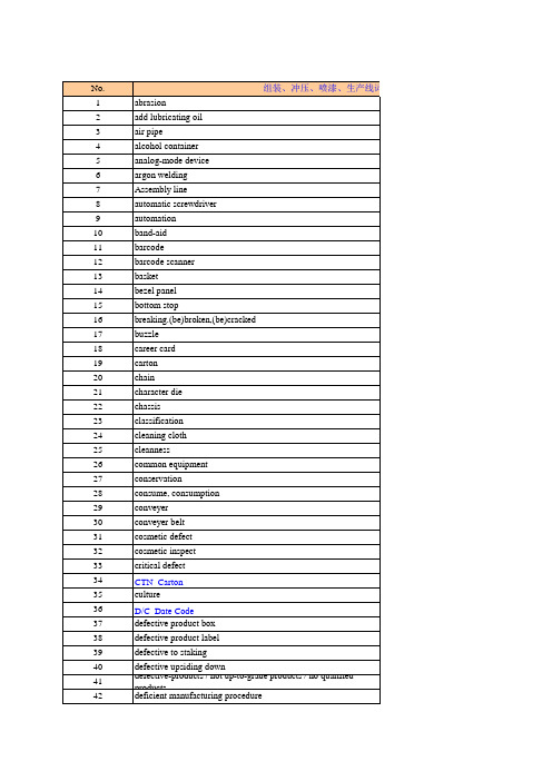
No. 1 2 3 4 5 6 7 8 9 10 11 12 13 14 15 16 17 18 19 20 21 22 23 24 25 26 27 28 29 30 31 32 33 34 35 36 37 38 39 40 41 42 abrasion add lubricating oil air pipe alcohol container analog-mode device argon welding Assembly line automatic screwdriver automation band-aid barcode barcode scanner basket bezel panel bottom stop breaking.(be)broken,(be)cracked buzzle career card carton chain character die chassis classification cleaning cloth cleanness common equipment conservation consume, consumption conveyer conveyer belt cosmetic defect cosmetic inspect critical defect CTN Carton culture D/C Date Code defective product box defective product label defective to staking
国际大电网会议标准清单

Thyristor controlled voltage regulators Parts 1
and 2
New optical access technology The automation of new and substations: why and how
existing
Optimization of power transmission capability
12. TB 078-1994
13. TB 082-1994 14. TB 086-1994 15. TB 092-1995
16. TB 093-1995
17. TB 097-1995 18. TB 112-1997
标准名称
CIGRE Technical Brochure on Grid Integration of Wind Generation(2009)
Conformance testing guideline for
communication in substations
Static synchronous compensator (STATCOM)
for arc furnace and flicker compensation
Modeling of gas turbines and steam turbines in
47. TB 234 48. TB 235 -49. TB 236 -2003 50. TB 237-2003 51. TB 238-2003 52. TB 239 53. TB 240-2004 54. TB 241 55. TB 242-2004 56. TB 245 57. TB 246 -2004 58. TB 247 -
中英文流体机械设备翻译词汇大全

towerreactorfluidfluid characteristicsgas-holderbibbPiping componentPipeFittingBendFlangeGasketPiping SpecialtyEnd ConnectionWeldingVarieties of WeldingType of WeldingWelding PositionDefects of WeldingHeat TreatmentConventional Heat Treatment Surface Heat Treatment InspectionTestFerrous MetalNon-metallic MaterialPiping Material Specification Material Take-off45°lateralEquipment NameVesselPipe Supports and Hangers Attachment of SupportType of Pipe Support spectacle blindquarter bendlong radius elbowdouble bevel grooveL-type supportO-ring“S”bendT-boltT-type strainerT-barcombination U and V grooveU-bolt“U”bendX-ray radiographydouble V groovey-type strainergamma radiographysafety factorerectionammonia gasreinforcing saddlessaddlefemale faceAustenitic stainless steel austenitic stainless steel pipe octagonal ring gasketdrawingcrateissueofficehalf couplingsemi-killed steeltracing pipetracing steampackingsaturated steamcold insulationhot insulationinsulation blockquoted pricequotationrupture diskexplosive weldinglimit of explosionnorthspare partsstand-byback to backstyrene-rubberpump housescalespecific heatspecific gravitywall thicknessschedule numbergratelightning preventeritemizeditemized equipmentflat nuttransmittertransformer roomelevationtitle blockstandardstandard pipe supportstandard drawingsurface preparationacrylonitrile-butadiene-styreneacrylic resinwave crestwave troughcorrugated metal gasket with asbestos inserted corrugated metal gasketbellow expansion jointglassglass clothglass tubeglass woo1gage glassBirmingham wire gagePoisson ratiomake-upreinforcement padstainless steelstainless steel pipeBrinell hardnessdepartmentbill of materialmaterial status reportProcurement; Purchasepurchase specificationpurchasing specification summary sheet referencereference drawingresidual stresschannelslot weldinggroove facegrooved metal gasketsketchthermo-paintblanklong radius returnslotnormally closednormally openvendor quotationvendor coordinative meeting future areafree on truckover-dimension cargo ultrasonic test superimposed loadclarifiersettlercountersunk screwlined pipeproductproduction design phase package unitcontractionsocket weldedsocket welding endsocket welding flange sockoletbell endgravity settlerorange colourendurance limitserratedfinshock loadimpact testimpact valueflush valveevacuationoutletcenter line of discharge preliminary stagefree on boardwindowblow-offsoot blowerpurgeperpendicularvertical installafion verticalalkyd enamelenamelmagnetic particle test roughnessstrainercoarseexpeditingbrittlenessquenchingextractoralignment tolerancemismatchlap weldinglapped jointlarge end threadlarge end plainbarometric legatmospheric pollutionatmosphereover haulcode numberside outlet elbowasbestos rope with inconeleye rodhinged expansion jointtied expansion jointpin with holebase teebase elbowstrap clampholdsingle bellowbendsingle U groovemonomersingle actionpacked slip joint spring washerspring hangerspring steelspring constant hangerresting type spring constant support spring supportresting type spring supportspring constantspring bracingelastic limitmodulus ofelasticitylightnitrogencanduitthermal conductivity factorconduit tubeguideroadstraight teestraight crossplasma weldingisothermal quenchingisothermal annealinglow alloy steellow-carbon steellow pressurelow pressure steambase plateflat on bottomprimary coatanchor boltfloor drainground levelabove ground pipingsloptankunder ground pipingearthquakeseismic loadseismic co emc ientprimary valvespot weldingpittingelectrical tracingarc weldingelectro corrosiontelephoneelectric heatercable trenchcurrentelectrical panelcapacitanceelectric-fusionelectric fusion weldingwirevoltageelectroslag weldingresistanceelectric resistance weldingelectric-resistance welded steel pipe backing weldspacertype of gasketwasherlifting lughangerhoisting beamdaviterection openingregulating valvequenching and temperingwing nutnitrile butadiene rubbertop plateJack screwflat on toppurchasing orderlocationtack weldpreset piecesdowel pindirectional stoplimit stopeastdynamic loaddynamic analysisplugplatingchromium-plated, chrome-plated galvanized steel pipe galvanized plain sheet galvanized wiregalvanized wire meshshort radius returnshort radius elbowshort codenipoletnipplereduction of areasection modulusslack quenchingforged steelwrought-iron pipeswageforgingforged valveforged steel clevisreducing swagebuild up weldingsymmetricbutt weldingbutt weldedbutt welded end welding neckflange welding neck collar convection section alignmentmultiple bellow multiport valve trunnionsecondary stresstwo-axis stopfoaminghair feltvalve pitflanged endblind flange, blind protective discflange facingfacing finishflangedlapped pipe end reactionsquare washersquare barsquare nutsquare head bolt orientationdirectionexplosion door moisture-proof packing winterizingcorrosion inhibitor anti-corrosive paint fire-proofingfire dooranti-sweatwater-proof packing rust-proof packing antirust paintventvent valvevent holenon-metallic gasket unpaved area nonferrous alloynon-rotary valvewaste heat boilerrimmed steelvictaulic couplingsubcontractorDecibelseparatorkey plananalytical engineering phaseanalyzer roommolecular sievephenolic paintincineratorwind loadwind velocityback run weldingpeak stresscrevice corrosionfuran resinfluoroplasticssymbolradiant sectionauxiliary boilercorrosioncorrosion testcorrosion allowanceappendant displacement; externally imposed displacement appendixaccessoryclad steelclad pipedry gas-holderdryerinduction hardeningrigidrigid hangerplatestrap steelsteel pipesteel pipe flangesteel ringsteel structuretop of steelreinforced concrete constructioncableleverhigh silicon cast ironhigh alloy steelhigh strength steelhigh-carbon steelhot quenchinghigh pressurehigh pressure steam isolating valvepartition wallinsulationsound insulation chromium steelchrome-molybdenum steel chromium-nickel steel inconelfeed water heaterroot valveroot gaproot crackincomplete penetration locker roomplantshop weldplant northplant limitengineering specification engineering manual engineering drawingtool steelman-dayman-hourindustrial waste water process airprocess flow diagram process gasprocess waterprocess liquidI-beamworking procedureworking pointworking loadoperating temperature operating pressure nominal pressurenominal diameterutility flow diagram metric ibreadpower factortapped; tappingsuppliercopolymerresonancethroughboaom of trenchmemberestimated priceestimatefixed saddlefix pointanchornatural frequencynatural frequency mode client; customer observation door, peep door pipe attachmentpiping layoutpiping arrangement plan piping classclass designationpiping attachmentpiping andline spanpiping flexibility analysis piping designpiping requisition sheet piping studypiping elementpiping support drawing bouom of pipetop of pipespool piecesleeperpiping trenchline spacingfitting to fitting coupling, full coupling clampshellnozzlelist of nozzlesnozzle orientationpipe rackpipe threadcapshoenetwork of pipespiping systemline listpipetubeinvertmoment of inertiaclosetgroutinggroutingdrumtank yardsmoothsmooth raised faceplanning stagecalcium silicatealuminosilicate fiberkieselguhrrolling supportboilerboiler feed waterfilterethylene perchloride paintsuperheated susceptivitysuper heatersuperheated steamover-sea mean levelburn throughwelding plate flangewelding endsymbol of weldwelded steel pipewelding procedure qualification test welding inspectionweld crackweldingiinebranch pipe welded directly to the run pipe weldoletoverlapwelding wirewelding electrodesynthesis towersynthetic rubberalloy steelalloy steel pipestructural alloy steelloadload caseconstant hangergirderredafter coolerpit; cratersliding saddlesliding supporttackle-blockseptic tankchemical analysis chemical cleaning chemical sewagering joint circumferential band ambient temperature ambient temperaturering joint faceeye boltring joint metal gasket flat ring gasketcirele bendepoxy, epoxy resin epoxy resin paintknock out drumheat exchangeryellowbrassgreygrey cast irontemper brittleness direct-fired heater recoverytemperingrotary kilnsummary sheetinter department check mixing valvemixertop of concretelive loadunionflareflare gasflame surface quenching maehine bolt mechanical vibration foundation; footingbasic designexcitationpolar moment of inertiadead-soft annealingultimate strengthquenchercatch basindrip legdrip valvelumped massextrudingmeasuring tankcomputer aided designcalculation sheettechnical specificationextra heavy, extra strongfeed tankstiffienerreinforcing ringheatercleatelastomer with cotton fabric insertionspiral-wound metal gasket with asbestos fillerelastomer with asbestos fabric insertionelastomer with asbestos fabric insertion and with wire r jacketed line, jacketed pipingjacketed valveslag inclusionmethanatortop of supportintermittent weldingdesuperheatersnubberdamping deviceshear stressinspection holeinspectionpart humbetconstructionbuildingkeyalternating stressdelivery orderalternating currentadhesivegussetangle steelhexagonal steel barfillet weldingangular rotationagitatorcontact corrosiongrounding; easthingearth lugreceivercontinue on drawingmatch linenodenode numberpitchcrystallizerbattery limit conditionoff sitemicroscopic testflat metal jacketed asbestos filled gasket clad; metal jacketing; cladding metalgas metal arc weidingmetal hosemetallic stuffingribfeedPTFE impregnated asbestos gasketTeflon impregnated asbestos packing intergranular corrosionfractionating towerfinished, finewellpurifiernet positive suction headnet weightstatic electricitydead loadlocal panelspot annealingsevere cyclic conditiondistancepolyurethanepolyurethanepolyurethane paintpolystyrenepolypropylenepolybutylenepolymerpolymethyl methacrylatepolyvinyl chloridepolyvinylidene fluoride polytetrafluoroethylenePTFE sliding platepolymerizerpolycarbonatepolyolefinpolyamidepolyethylenepolyester resinpolyester fibersabselute elevationroot mean squarehomopolymeras built drawingstart-upkick-off meeting; launching meeting cotter pintensile strengthbending strengthcompressive strengthhardenabilityadjustable cleatadjustable supportmalleable ironflammableair separation facilityair coolerairorificeorifice flangecontrol roomspanquick closing valvequick opening valvequick couplingwide flanged beammineral woolflaring testtension testtension stresshandrailbluecold-drawing seamless pipecold shortnessrefrigerantcold workingcold springcold flowcondensercoolingcooling towercooling towercold loadcold rollingforcemomentcouple of force vertical welding asphaltbituminous painttie plateconnecting rodtie rodhook up drawing interlocktop of beambeamboth end threadboth ends plain reformercritical pointcritical temperature critical pressure temporary load phosphor bronzeflow diagramflow metersulphuric acidradius of gyration hexagonal nut hexagonal head bolt floorstair; stair way funnelfurnace tubefurnacehalogen gas leak test shoulderaluminumalaminium sheet aluminum magnesium aluminum bronzegreenneoprenechlorinated polyvinyl chloride chlorinated polyethertapnutboltbolt circlethreadedthreaded endthreaded flangethreaded joint, pipe threaded joint threadoletspiral plate heat exchangerspiral welded steel pipehelical gas-holderstud boltbare iineRockwell hardnessMartensitic stainless steelmastic weatherproof coatingex wharfpulsationpulsating stressgross weightcliprivetAmerican standard taper pipe thread American wire gagedoormanganese bronzedensitysealing oilblanketareain-planefinishing coatout-planeface to facefire extinguishernomenclaturemodelbase metalmother liquorwoodwood blockwooden boxmolybdenum steelbevel for inside thickness inner ringinternal forcebevel for combined thickness internal pressure stressfire brickalkali-proof paintheat resisting steelincoloyheat-proof paintHastelloycorrosion resistanceacid-proof paintseismic classsouthdeflectionflexible tubenylon plasticcounter clock wiseurea resinnickel steelnickel copper alloyfreezing pointtorquetorsional stress concentrationdischarge valveexhaustblow downblowdown valveblow down tankdraindrain valvedrip ringdrain funnelpad type flangeby passby-pass valvefoam glassfoamed concretecellular polystyrenefoam monitorfoam hydrantfoam fire-fightingfoam stationswitch boardsubstation, switch roomcompanion-flangeejectorsprayerspray nozzleshelterborosilicate glassexpansion jointexpansion boltapproved for planningapproved for designapproved for constructionfatigue limitfatigue testeccentric reducerfrequencyflat gasketplain washerplain endflat weldingwelding-on collarflat metal gasketplanplatformparallelevaluationgroovebeveled endvacuum breakervacuum breakerpaving areageneral structure low-alloy steel general carbon steelspectrum analysisurushiol resin paintcylindergas welding; flame welding vaporizerporosityair tightness testfusion gas weldingcavitation erosiongas-shielded arc weldinggas analysisgaseous corrosiongas chromatographpneumatic teststeam drumleadwallsupport on wallblock valvecut to suittangent linebronzehydrogen embrittlementhydrogenvarnishclean outrequisitioningspheroid, spherical tankspheroids annealingspherical washernodular cast iron; nodular graphite iron ball type expansion jointarea limitzone iimityield pointyield limitsampling valvesampling connectionsample coolerfull jacketedflat face; full faceskirtfuel gasfuel oilthermocouplethermosetting plasticshot workingthermal expansion coefficienthot waterhot-water tracingthermoplasticthermal cyclethermal stressthermal stress analysisheat affected zonehot rollinghot-rolling seamless pipemanholepersonal protectionman-monthtoughesssolvent cementsolutionsolution storage tankmelting pointmelterflexibility characteristicflexibilityflexibility factorflexibility stressvisual inspectioncreep rupture strengthcreep limitinletcenter line of suctionhose valvehose connectionhose stationsoftenercork woodsoft waterlubricating oilsprinklerplug weldingtriangular support’teethree way valvebulk materialblisterflash pointflash drumuprisercaustic sodaburnerequipment listequipment item numberdesign specification summary sheet basic engineering design data design managerdesign temperaturedesign documentdesign response spectrumdesign pressuredesign scismic coefficientdesign notefacilitiesradiographic testchillerdarkapprovalcheck listnitridationchromizingchromized steelsoak-away pitaluminizingcarbonizationboostersanitary sewerpig ironsound intensitysound pressure levelsound sourceeconomizerfull water testhumiditywet gas-holderasbestos boardasbastos clothasbestos ropeasbestos fabricgraphite phenolic plasticsnaphthaageing treatmentemergency valvesight glasscommissioninghand-operated valvemanual and automatic inert gas tungsten arc welding handholewrought ironresindata sheetdata basequantityattenuation constantdouble extra heavydouble bellowcorrugated metal double jacketed asbestos filled gasket double jacketed gasketdouble U groovedouble offset expansion “U”double branch elbowwater traatmentwater hammerwater quenchingcold quenchingwater coolerwater-gas steel pipefinishing cementwater monitorwateringhorizontal installationhorizontalhydraulic testclock wisedescriptiongauze strainerTeflon tapcrossloose plate flangeloose hubbed flangelap joint flangeplasticplastic pipeplasticitysour gasarithmetical average roughness height gravel pavingtongue faceacetal plasticindexlock nuttitaniumcarbon steel pipecarbon steelmagnesium carbonateporcelain enamelceramicspecial flangespecial supporttrapezoid threadvolumeskylightnatural white rubber gasketnatural gasnatural rubberslip type expansion jointpackingstuffing box glandpacking boxcaulking materialskip weldingferritic alloy steel pipeshut-downventilating roomtypical pipe supporttypieal installation concentric reducercopperaccuracy of take-offbidlens gasketmale faceraised facestub endfiguredrawing numberlegendcoatingpaintingsurgingthrustannealingcradlestooldesulphurization reactor degasifierdemineralized water demineralizerdeaeratoroval ring gasketellipsoidal headbevel for outside thickncss outer ringexternal forceexternal pressure stress externally applied load bending momentbending testbending stresselbowelboletuniversal jointuniversal type expansion joint checkered platedouble-acting limit stophazardous area classificationhazardous area planmicro crackVickers diamond hardnessmaintenance roomincomplete fusion; lack of fusion displacementdisplacement stress rangedisplacement stressthermometerthermowellfileeddy current testcontaminationcontaminated rain waterseamless steel pipeinorganic zinc-rich paintnon graphited compressed white asbestos gasket non-destructive testingnon-itemized equipmentwestadsorbersuction valvesound-absorbingabsorberscrubbereye washer and showereye washer stationfine threaddownadvanced certified finalfiber reinforced thermoplasticsfield weldwire gagerestriction orificestopstopperlimit rodrestraintintersectionphasesweepoletdetaildetail designdetail design issueprojectjob No.proiect status reportproject managerbatterylimitinside battery limitproiect review meetingrubberrubber hoserubber tuberubber pavingstress relieffire fighting truckfire hose connectionfire waterfire pumphydrantsilencersilencernitric acidpinpinned shansmall end threadsmall end plaincheckbracingslant washermitre bendlatroletharmonic analysisleak testunloading valveshaped steelrevisiontrim to suitallowable stressallowable stress rangebattery roomcantilever supportcyclonesnow loadinquirycireulatloncooling water supplycooling water returncirculating waterflattening testpressure rating, pressure rating class classmanometerpressure balanced expansion pressure testpressure-temperature rating compressor housecompressed asbestos class gasket compression stressargon-arc welding,stackpercentage elongationductilityexcessive spatterrock woolbrinechlorhydric acidcolouroverhead weldingoxygenundercutownerliquefired petroleum gasliquid penetrant testlevel gaugeliquid chromatographhydraulic snubberprimary stressone end threadinstrument airinstrument panelapparatusinstrumental analysisethylene propylene rubber ethylene propylene diene monomer existing steel structurereducing nipple; swage nipple reducing flangereducerreducing couplingreducing teereducing crossreducing elbowcathodic protectionacoustic vibrationpotable waterstrain; deformationstrain energystressstress range reduction factur stress corrosioncoefficient of stress concentration stress intensification factor fluorescent penetrant inspection hardness testrigid foam rubberbraze weldinghard leadhard waterpermanent filteruserclient change noticehigh-quality carbon steeloil quenchingasphalt feltasphalt feltshielded metal arc weldingtoxicorganic silicon paintright hand threadrain watertroughembedded part; inserted plate preheatingpreheaterprefabricatedfabricated pipe bendmemberraw waterroundnessround steelround head boltcircumferential stress; hoop stress taper pintransportationon streamheating mediumreboilerreheaterregenerationregenering towerrecycleprflling towernoise levelrollingwrought-steel pipeviscositylighting; illumination corrugated bendpin holeperlitevacuumvacuum testtrue northamplitudekilled steelevaporatordistillation towersteam tracingsteaming outsteam condensatevapor pressureintegral pipe flangesolid metal serrated gasket normalizingpoint of supponstrutringsupport ringresting supportlugbranch connectionbosslegrun pipedirect currentladdershear lugpreparationdrawnmanufacturer; vendormass spectrometric analysis vermiculitemedium alloy steel neutralization tankinter coolerprocess annealingmedium-carbon steel centerlinecenter to endcenter to facecenter to centermedium pressuremedium pressure steamcounter weight hangerweightcritical pipingheavy oilperiodshaftisometric drawingbearingaxial movement type expansion jointaxial stressbead weldingmost frequent wind directionprincipal stressstorage roomtankcolumnpole type supportcast steelcastingcast ironcast iron pipecast valvedisciplineconverterpilepacking liststatus reporttaper pipe threadseal-welded taper pipe threaded jointdye penetrant inspectiondocumentationpurpleautomatic analysisautomatic submerged arc weldingself tapping screwself springself-sealingfreefree to slidefree vibrationconsolidated piping material summary sheet brownheader, manifoldheader valvegeneral plot planlongitudinal stresswalk way, gangway, access way routing studyflame arresterdamped vibrationassemblydrillcertified finalcoordinateorigin of coordinate塔反应器流体流体特性气柜(水)龙头管道组成件管子管件弯管法兰垫片管道特殊件端部连接焊接焊接种类焊接形式焊接位置焊接缺陷热处理普通热处理表面热处理检验试验黑色金属非金属材料管道材料规定材料统计45°斜三通 设备名称容器管道支吊架管架零部件管支架型式8字盲板90°弯管k半径弯头K形坡口L形管架O形环S形弯管T形螺栓T型粗滤器T型钢U-V组合坡口U形螺栓U形弯管V形坡口X射线照相X形坡口y 型粗滤器γ射线照相安全系数安装氨气鞍形补强板鞍座凹面奥氏体不锈钢奥氏体不锈钢管八角环形垫片拔制板条箱版次办公室半管接头半镇静钢伴热管伴热蒸汽包装饱和蒸汽保冷保温保温块报价报价书爆破片爆炸焊爆炸极限北备品备件备用背至背苯乙烯橡胶泵房比例比热比重壁厚壁厚系列号篦子板避雷针编位号的编位号设备扁螺母变送器变压器室标高,立面标题栏标准标准管架标准图表面处理丙烯腈—丁二烯—苯乙烯丙烯酸树脂波峰波谷波纹金属包嵌石棉垫片波纹金属垫片波纹膨胀节玻璃玻璃布玻璃管玻璃棉玻璃液位计伯明翰线规泊松比;横向变形系数补充补强板不锈钢不锈钢布氏硬度部门材料表材料情况报告采购采购说明采购说明汇总表参考、基准参考图残余应力槽钢槽焊槽面槽形金属垫片草图测温漆插板长半径180°弯头长孔常开厂商报价厂商协调会场地敞车上交货超尺寸运输超声波探伤超载沉淀池沉淀器沉头螺栓衬里管成品成品设计阶段成套设备承包商承插焊的承插焊端承插焊法兰承插支管台承口澄清器橙色的持久极限齿形翅片式导向板冲击荷载冲击试验冲击值冲洗阀抽空;排空出口出口中心线初步阶段船上交货,离岸价格窗吹出吹灰器吹扫垂直,正交,垂直的垂直安装垂直的,立式的醇酸瓷漆瓷漆磁粉探伤粗糙度粗制的催货脆性淬火萃取器错边量错位搭焊搭接接头,松套连接大端带螺纹大端为平的大气腿大气污染大气压大修代码带侧向口的弯头(右向或左向)带铬镍合金丝的石棉绳带环头拉杆带铰链膨胀节带接杆膨胀节带孔销带支座三通带支座弯头带状卡待定单波单侧偏置U形膨胀弯管(| ?形) single offset “U”单面U形坡口单体单向滑动填料函补偿器弹簧垫圈弹簧吊架弹簧钢弹簧恒力吊架弹簧恒力托架弹簧架弹簧托架弹簧系数弹簧支撑架弹性极限弹性模量淡(浅)色的;轻的氮气导管导热系数导向架道路等径三通等径四通等离子焊等温淬火等温退火低合金钢低碳钢低压低压蒸汽底板底平底漆地脚螺栓地漏地面地上管道地下槽地下管道地震地震荷载地震系数第一道阀;根部阀点焊点蚀电伴热电弧焊电化腐蚀电话电加热器电缆沟电流电气盘电容电熔(弧)焊钢板卷管电熔焊电线电压电渣焊电阻电阻焊电阻焊钢管垫板焊垫环垫片的型式吊耳吊架吊梁吊柱吊装孔调节阀调质蝶形螺母丁腈橡胶顶板顶开螺栓,顶起螺栓顶平订货单;订购单定位定位焊定位块定位销定向限位架定值限位架东动力荷载动态分析堵头镀层镀铬的镀锌钢管镀锌铁皮镀锌铁丝镀锌铁丝网短半径180°弯头短半径弯头短代码短管支管台短节断面收缩率断面系数断续淬火锻钢锻铁管锻造,型钢锻造的,锻造锻造阀锻制U形夹锻制异径管堆焊对称的。
飞利浦电动剃须刀使用说明书

H-SERIES FUEL TRANSFER PUMPS FR1200, FR2400, FR4200, FR4400, FR600, SD1200, SD600Installation and Operation ManualTable of Contents Limited Warranty PolicyFill-Rite Company warrants the goods manufactured shall be free from defects of materials and workmanship. Specific warranty details for individualproducts can be found at .Thank You!Thank you for your loyalty to the Fill-Rite ® brand of fuel transfer pumps.Your safety is important, so please read and thoroughly understandthe procedures set forth in this manual. In addition, please save theseinstructions for future reference and record the model, serial number,and purchase date of your fuel transfer pump. Protect yourself as wellas those around you by observing all safety instructions and adhering toall danger, warning, and caution symbols. Please register your Fill-Rite ®product via /product_registration .IMPORTANT RETURN POLICYPlease do not return this product to the store . For all warranty and productquestions, please contact Fill-Rite Technical Support at 1 (800) 720-5192 or ***********************************(M-F,8AM–5PMET).Limited Warranty Policy .......................................................................2About This Manual ...............................................................................2Symbols and Definitions ......................................................................3Before You Begin .................................................................................3Safety Information ...............................................................................4Installation ..........................................................................................512V DC and 24V DC Wiring Instructions ...............................................7115V AC Wiring Instructions ................................................................10Operation Instructions .......................................................................12Security .............................................................................................12Troubleshooting Guide .. (12)Specifications and Models ..................................................................14Performance Curves ...........................................................................17Accessories ........................................................................................19Pump Service Kits (21)Certifications (22)Motor Tag (22)Before You BeginAbout This ManualFrom initial concept and design through final production, your Fill-Rite fuel transfer pump is built to provide years of trouble-free use. To ensure the safety of yourself and those around you, it is critical that this manual is read in its entirety prior to attempting to install or operate your new purchase. We strongly urge that any installer and operator become familiar with the terms, diagrams, and technical data in this manual and pay close attention to warningsymbols and definitions. At Fill-Rite, your satisfaction with our products is paramount. If you have questions or need assistance with your product, please contact Fill-Rite Technical Support at 1 (800) 720-5192 (M-F, 8am-5pm ET).• Adjustable Electrical Junction Box Rotates 180 degrees to provide ease of electrical wiring installation in tight quarters no matter the inlet bung location • Reliable, Heavy-Duty Power Switch Lever Features a cast metal stop that withstands heavy use in themost rugged environments • Locking Bar Defense Elongated bar simplifies the pad locking process to prevent theft • Focused Component Weight Reduction Preserves expected heavy-duty performance while improving installation ease • Premium Paint ShieldAn exemplary corrosion resistant barrier for long field life• Thermally Protected MotorPrevents overheating to ensure maximum motor life• Telescoping Inlet Metal Suction Pipe*Adjustable from 20 to 34 inches in length, allowing for universalinstallation on a multitude of tank sizes and shapes*Not included with SD models• Intake Strainer SafeguardProtects the pump by blocking particles created by contamination• Certifications – UL, cULFueling RequirementsThe Fill-Rite FR1200, FR2400, FR4200, FR4400, FR600 as well as SD1200 and SD600 models are designed and approved for use with the followingflammable and combustible fluids: gasoline and gasoline blends up to 15% or E15, diesel, biodiesel blends up to 20% or B20, kerosene, and mineral spirits. Please take all necessary precautions when handling flammable liquids.Power Source RequirementsDepending on the Fill-Rite model, supply line power will either be 12V DC, 24V DC, or 115V AC. The pump motor nameplate located next to the switch lever will provide detailed electrical information. Please refer to the appropriate electrical instructions found starting on Page 7 (DC power) or Page 10 (AC power).Items that may be needed for installation:Steel pipe wrench 14-24", open end wrench or socket (7/16", 11mm), T-25 Torx driver, utility knife, angle grinder or hacksaw (optional), wire cutters, wire stripper/crimper, and thread sealant (optional).NOTE : Fill-Rite provides Teflon ® tape for all models as listed on Page 16.H-Series Fuel Transfer Pumps Have the Following FeaturesSafety InformationTo ensure a safe installation and proper equipment operation, please read, understand, and adhere to all DANGER/WARNING/CAUTION and other NOTICES.Installation1-2"Min.1-2"Min.Stationary Tank For stationary fuel tanks, the pump mounts to the tank bung by way of the pump inlet flange. Given the different sizes of stationary fuel tanks, a custom suction or inlet pipe may be necessary. We recommend 1” NPTblack iron pipe that is extended to a length of at least 1-2” from the bottom of the tank, with the bottom of the pipe cut to an angle between 30-45 degrees for improved flow.A stationary tank must be equipped with a vent cap. (Diagram 1)Mobile TankFor mobile fuel tanks, the pump mounts to the tank bung by way of the pump inlet flange.For Telescoping Steel Suction PipeAllow telescoping tube to extend fully to the bottom of the tank. For Custom or PVC Suction PipeTo avoid penetrating the tank, we recommend leaving a minimum of 1-2”of the pipe off the bottom of tank. We further recommend cutting thesuction pipe to a 30-45 degree angle for improved flow.The mobile tank must be equipped with a vent cap. (Diagram 2)Vent CapVent CapInstallation ProcedureStep 1: (Optional) Inlet Flange RemovalLoosen (4) 1/4" bolts using 7/16" wrench or socket. Detach inlet bung from pump, retain bolts, screen, and gasket.Step 2: Using either included suction pipe or custom pipe, threadpipe into inlet bung 1.5 to 2.5 turns past hand tight with pipe wrench.Use appropriate sealant for fuel transfer.Step 3: Thread inlet bung with attached suction pipe onto tank 1.5 to2.5 turns past hand tight. Use appropriate sealant for fuel transfer.Step 4: (Only if Step 1 utilized) Place screen in screen pocket on the inletbung, mount gasket, then place pump on tank bung. Align holes and insert(4) 1/4" bolts and tighten with 7/16" wrench to 40 in.-lbs. minimum.Step 5: Remove junction box cover via (2) T-25 screws and locate wires.DC Voltage: 2 wires, Black and Red; AC Voltage: 3 wires, Black, White,and Green which is attached to internal ground screw. Ensure that gasket remains in place upon re-attachment of junction box.† opening into junction*. For AC models, attach40 in-lbs. The nozzle boot has two available position placements.* Black cable gland only included with DC models†1/2" NPT to cable gland, bronze fitting per ATEX on HE Models(2) T-25 SCREWS JUNCTION BOX CAP GASKETGASKETTANK BUNG SCREEN ½" NPTCONDUIT HOLE, THREADED JUNCTION BOX CAP (CAN BE ROTATED 180°)EARTH GROUNDSYMBOLHOLE POSITION POSTStep 712V DC and 24V DC Wiring InstructionsFR1200 / FR2400 / FR4200 / FR4400 / SD1200 Series DC Transfer PumpInstructions Before Proceeding with DC WiringThe pump needs to be electrically bonded to a vehicle frame for mobile tanks or a ground rod for stationary tanks. To electrically bond pump for mobile application, remove the external factory installed green bonding screw located on the junction box cover (Diagram 3). Insert this screw through eyelet of furnished green bonding wire assembly and refasten it securely to the junction box. The other end of the wire is to be stripped of insulation and the bare wire securely bonded to the vehicle or on/off road trailer frame for mobile tanks (Diagram 4). For bonding with stationary tanks, attach a ground wire to a ground rod and the tank itself (Diagram 5). The distance may be greater than the supplied grounding wire.DC Wiring Instructions Diagram 5ATTACH GROUND WIRE TO GROUND ROD1. Remove pump’s electrical junction box cover and straighten the red and black wire.2. Screw the furnished cable connector into 1/2" NPT conduit opening on the junction box.3. Strip 3" of the outer covering from one end of the furnished electrical supply cable.* Be careful not to damage the black and red wire insulation.4. Loosen cable connector nut and pass the stripped end of the furnished cable through the cable connector. Tighten the cable connector nut.5. Strip 1/2" of the insulation from the ends of the red and black cable wires. Using the furnished wire nuts, connect the cable wires to the pump wires matching the colors. IMPORTANT: Be sure no bare wire is exposed.6. Fold wires into junction box and replace, making sure the cover gasket is in place. Make sure all screws are seated so there is no space between the frame and the junction box (see Step 6 diagram on Page 6). *12 AWG cable not supplied with pump only models ATTACH GROUND WIRE TO VEHICLE BODY½" NPT CONDUIT HOLE, THREADED JUNCTION BOX CAP (CAN BE ROTATED 180°)EARTH GROUNDSYMBOLDiagram 4Mobile Tank Wiring to a Vehicle Electrical System1. Before electrical installation, place the switch lever into the OFF position to prevent accidental spillage once power is engaged to the motor.2. Pass the electrical wires to the source of the vehicle power system, supporting as necessary and protecting them from sharp edges, heat, or anything that could cause damage.3. To determine if the vehicle electrical system is negative (-) or positive (+) ground, check the battery marking of the terminal that is wired to the vehicle frame or motor block. The red wire from the pump will connect to positive battery post and the black wire from the pump will connect to negative battery post. These instructions focus on COMMON negative ground systems. UNCOMMON positive systems are a rare occurrence. Reference the drawing on Page 9 for information on positive ground systems.4. Fill-Rite requires installing a fuse holder and fuse (not provided) for protection of the purchased pump. Attach one end of the fuse holder to the end of the ungrounded wire, making a solid connection. The other end of the fuse holder is then attached to the ungrounded side of the battery, as close to the battery as possible. Make a solid electrical connection to the grounded side of the battery with the remaining wire. Utilizing a battery terminal connection (not provided by Fill-Rite) is required for completion of the electrical circuit.5. Check all connections to make sure they are connected per instructions and all electrical codes. Install fuse (30 amp fuse for 12V DC; 20 amp fuse for 24V DC) into the fuse holder. Installation is now complete.Stationary Tank Wiring1. Before electrical installation, place the switch lever into the OFF position to prevent accidental spillage once power is engaged to the motor.2. Fill-Rite requires installing a fuse holder and fuse (not provided) for the protection of the purchased pump.3. Attach one end of the fuse holder to the red pump wire, as close to the battery or power source as possible. Make a solid connection to the positive terminal of the power source with the other end of the fuse holder. Make a solid connection with the black pump wire to the negative terminal of the power source.4. Check all connections to make sure they are connected per instructions and all electric codes.5. Install fuse (30 amp fuse for 12V DC; 20 amp fuse for 24V DC) into the fuse holder.6. The installation is now complete.Positive Ground System (Uncommon)This electrical system is uncommon within most vehicles utilizing a 12V DC power source. The chassis of the vehicle is connected to the positive (+) terminal of the battery.Fuse to be located outside of hazardous area, as close to the power source as possible. If the wiring from the power source to the pump is greater than 18', refer to the applicable Electrical Code (national, international, or local) to ensure the wire is of the correct size for the application.Negative Ground System (Common) This electrical system is common within most vehicles utilizing a 12V DC power source. In this instance, the positive battery terminal supplies power to all devices such as the ignition system. The negative (-) terminal is connected to the vehicle’s frame. Fuse to be located outside of hazardous area, as close to the power source as possible. If the wiring from the power source to the pump is greater than 18', refer to the applicable Electrical Code (national, international, or local) to ensure the wire is of the correct size for the application.FUSE FUSECOMMON UNCOMMON30 amp fuse for 12V DC 20 amp fuse for 24V DC 30 amp fuse for 12V DC 20 amp fuse for 24V DC Mobile Tank Wiring to a Non-Vehicle SystemWhile rare, there are instances where a 12V or 24V DC Fill-Rite fuel pump does not operate from a vehicle’s electrical system. In these cases, we recommend calling Fill-Rite Technical Support at 1 (800) 720-5192 (M-F, 8am-5pm ET) to discuss your specific situation. Most of these applications will require equipment not supplied by Fill-Rite. In addition, we want to ensure that the circuit will be able to handle the necessary power requirements of the pump.115V AC Wiring Instructions for FR600 / SD600 AC Fuel Transfer Pumps115V AC Wiring Procedure1. Remove the junction box cover and straighten the wires to make sure the stripped wire ends are accessible outside the junction box.2. Install rigid conduit and appropriate wiring from power source to the junction box to maintain the explosion-proof integrity.3. Connect the pump wires to the power supply lines according to the wiring diagram. Be certain to properly insulate the connections with the appropriate wire nuts or other connectors. NOTE : The ground wire MUST be connected. Ground wire connection is inside the junction box (Diagram 6b).4. Fold the wires back into the junction box and replace the cover, making sure the cover gasket is in place.115V AC Pump Junction Box (FR/SD600 Series AC Fuel Transfer Pumps)115V AC Wiring Diagram for FR/SD600 AC Fuel Transfer Pumps.A ground wire must be included within the supply line power cable.This wire must be connected to the ground screw terminal on the inside of the junction box surface.Diagram 6a Diagram 6b115V AC Wiring Diagram INTERNAL GROUND SCREWSwitch Level Installation InstructionsEffective March 7, 2022, the fuel transfer pump on/off switch lever will need to be installed in the field. Please see Figure 1 for a visual guide on the proper installation of this lever.Figure 1Security1. If equipped, reset meter to “0” (do not reset while in use as this3. Move the switch lever to the “ON” position to power the pump (Diagram 7).4. Insert the dispensing nozzle into the container to be filled.5. Operate the nozzle to dispense fluid; release nozzle when thedesired amount of fluid has been dispensed.6. Move switch lever to the “OFF” position (Diagram 8) to turnoff the pump.7. Remove the dispensing nozzle from the container being filled andstore it in the nozzle boot.Operation InstructionsTroubleshooting The following troubleshooting guide is provided to offer basic diagnostic assistance in the event you encounter abnormal service from your Fill-Rite fuel transfer pump. If you have questions, please feel free to contact Fill-Rite Technical Support at 1 (800) 720-5192 (M-F, 8am-5pm ET) or byemail at *************************.Please disconnect all power supply sources from either your AC or DC pump prior to performing any service or maintenance,as well as relieve any pressure within either the suction tube or discharge hose. Failure to do so can result in damage to the "ON" Position "OFF" PositionYour Fill-Rite fuel transfer pump is equipped with a locking link located next to the switch lever for security. With the pumpturned off and the nozzle in the stored position, a padlock can be inserted throughthe locking link and the nozzle handle.Fill-Rite recommends a commercial gradelaminated steel padlock with an adjustableshackle (Diagram 9).Diagram 7Diagram 8Diagram 9SWITCH LEVERNOZZLE BOOT SWITCH LEVERNOZZLE BOOTTroubleshooting (continued)Specifications and Models† Warranty details can be found at *HE pump only models have BSPP outlets*Power cord not included in pump only modelsA series of fuel transfer pumps with UL/cUL, ATEX, IECEx, CE, EAC, and INMETRO certifications that are compatible with gasoline, diesel fuel, blended fuels such as biodiesel up to 20%, gasoline with up to 15% ethanol, mineral spirits, and kerosene.| H-SERIES FUEL TRANSFER PUMPS INSTALLATION AND OPERATION MANUALFR4200 (Dimensions displayed in inches)3.44.32.58.413.011.14.28.42.54.311.813.7FR1200, FR2400, FR4400, FR600, SD1200, and SD600 (Dimensions displayed in inches)H-Series Model Information: FR1200, FR2400, FR4200, FR4400, FR600, SD1200, SD600H-Series Model Information: FR1200, FR2400, FR4200, FR4400, FR600, SD1200, SD600 (continued)HE-Series Model Information: FR1200E, FR2400E, FR4200E, FR4400E2400 Series Performance Curve4400 Series Performance CurveMETER STRAIGHT PIPE FILTER HEADSTRAIGHT PIPEProper Accessory Configuration AccessoriesAccessories (continued)2122*KIT120BD not called out in diagram abovePump Service KitsFIL-MN-712v.3InstallationPump must be installed in compliance with EN 60079-14 or IEC 60079-14, as applicable.Material of ConstructionMaterials of construction of the external surface of the unit: painted steel, painted cast iron, painted aluminum, zinc plated steel.Materials of construction of the wetted parts: cast iron, zinc plated steel, 300 series stainless steel, bronze, carbon, ceramic, polyester, fiber, fluorocarbon, buna.Repair and MaintenanceContact the place of purchase for warranty repair and maintenance.Specific Conditions of Use1. Consult the manufacturer if dimensional information on the flameproof joints isnecessary.2. ISO Class 4.6, M5 hex-head screws (Yield Stress 240 MPa) shall be used to replacethe DC Motor terminal cover fasteners.3. ISO Class 8.8, M6 hex-head screws (Yield Stress 640 MPa) shall be used to replace the DC Motor motor tie-rod fasteners.4. An electrically conductive hose and nozzle must be used with flammable liquids.To minimize static electricity buildup, always keep the nozzle in contact with thecontainer being filled during the fueling process.Motor Tag InformationThe motor tag on your Fill-Rite pump contains important technical and performance information. Be certain this label remains affixed to the pump at all times.Safety Testing ApprovalsThe Fill-Rite line of pumps have been safety tested for regulatory compliance. This product family is approved by UL/cUL. For the “E” series products they are approved to ATEX, IECEx, INMETRO, EAC, and CE.2809The following standards were used to show compliance in the European Union:EN IEC 60079-0:2018, Ed 7 “Explosive atmospheres – Part 0: Equipment – General requirements”EN 60079-1:2014, Ed 7 “Explosive atmospheres – Part 1: Equipment protection by flameproof enclosures “d””EN ISO 80079-36:2016, Ed 1 “Explosive atmospheres – Part 36: Non-electrical equipment for explosive atmospheres – Basic method and requirements”EN ISO 80079-37:2016, Ed 1 “Explosive atmospheres – Part 37: Non-electrical equipment for explosive atmospheres – Non electrical type of protection constructional safety “c”, control of ignition source “b”, liquid immersion “k”” Directive 2014/34/EU – Equipment and protective systems intended for use in potentially explosive atmospheres.Directive 2011/65/EU – Restrictions of the use of certain hazardous substances in electrical and electronic equipment.The following standards were used to show compliance for IECEx certification:IEC 60079-0:2017, Ed 7 IEC 60079-1:2014, Ed 7Motor Tag InformationThe Motor Tag on your Fill-Rite pump contains important technical and performance information. Be certain this label remains affixed to the pumpat all times.II 2 G Ex db h IIA T5 or T6 Gb FM19ATEX0019X IECEx FMG19.0013XEx db IIA T5 or T6 GbFill-Rite Company 8825 Aviation Drive Fort Wayne, Indiana 46809 USAT 1 (800) 720-5192 1 (260) 747-7524 F 1 (800) 866-4681 | | 。
送电线路规程2012

DL/T832-2003 GB/T1179-2008
电工用铝包钢线 Aluminium-clad steel wires for electrical purposes
GB/T17937-2009
型线同心绞架空导线 Overhead electricial conductors-Formed wire,concentric lay,stranded conductors 电工圆铝线 Round aluminium wire for electrical purposes
交流线路带电作业安全距离计算方法 Live working-Minimum approach distanced-method of calculation
GB/T19185-2008
1000kV特高压交流输变电工程过电压和绝缘配合 Overvoltage and insulation coordination of 1000kV UHV AC transmission project
架空绝缘配电线路设计技术规程 Design technique requlations for overhead distribution lines with insulated conductors
DL/T601-1996
110~500KV架空电力线路施工及验收规范 Code for construction and acceptance of 110~500kV overhead transmission line 750KV架空送电线路施工及验收规范 Code for construction and acceptance of 750kV overhead transmission line
2010
德力西JD-5S 电动机综合保护器 说明书

JD-5S Series Electric Motor Integrated ProtectorUser Manual□Please carefully read this User Manual before the installationand operation of this product, and keep it properly for futurereferenceI. Overview1.1 Scope of ApplicationJD-5S series electric motor integrated protector is used in the AC 50/60Hz power supply circuit with a voltage 380V and below to form an electric motor control circuit together with the switching circuits such as AC contactor. if found abnormal working states such as open phase, overload, and stall of main circuit of electric motor, please disconnect the contact of the switching device and cut off the three-phase power supply of electric motor timely to protect the electric motor reliably. JD-5S is an upgraded product of JD-5 product, and the setting current of the protector is set directly according to the rated current marked on the nameplate of the electric motor before use for convenient operation by users; there are technologies of multiple starting timeout options and the overload protection has inverse time limit performance, the needs of various types of motors starting from light load to heavy load can be adapted. The product has functions that there is a digital tube do display the setting current value, the run and fault status light-emitting tube is used to display, and there is pointer ammeter drive output.Standard: GB/T 14048.41.2 Model definitionRated control supply voltage Us:AC220V;AC380VRated current: 1A~9.9A10A~99ASpecification codeElectric motor integrated protectors1.3 Normal working conditions and installation conditions1.3.1 Working environment: the altitude does not exceed 2000 meters; The ambient temperature is not higher than +40℃and not below than -5℃; the voltage change range of the rated control power supply is 85%-110% of the rated voltage; the product is installed in places where the medium has no serious vibration and explosion hazard, and there are no gases and dust in the medium sufficient to cause corrosion to the metals and damage to the insulation, and there is rain and snow invasion.1.3.2 Vertical or horizontal installationII. Structural Characteristics and Working PrincipleJD-5S electric motor integrated protector has protections for overload, stall, thermal memory, open phase, three-phase imbalance, and start-up timeout. This protector adopts current sensing technology, and has a relay output interface; the whole series is of the core-through type. This protector has advantages of simple structure, reliable action, and convenient operation.III. Technical ParametersRated operating current Ie range 1A~9.9A 10A~99ARated insulation voltage, Ui AC380VRated operating voltage, Ue AC380VRated control supply voltage, Us AC50/60Hz AC220V AC380VUse category Main circuit AC-3; matched auxiliary contact (body) AC-15 Shell protection grade IP40Number of types of contacts of aux.circuit1 normally openOperating voltage and operating currentunder the use category of aux. CircuitAC-15 Ue: AC220V Ie: 0.47ARated ultimate short circuit current matedSCPDRT16-00, 6ATrip level 10A, 10, 20, 30Overload protection characteristics When the actual operating current of the motor is 1.05 times of the rated operating current, the protector operation protection time is greater than or equal to 2 h; when the actual operating current rises to 1.2 times, the protector operation protection time is less than 2 h; when the actual operating current rises to 1.5 times, the protector operation protection time is less than 2 min.Range of matched DC meter head(Rated current) 0~5A (1A~4A); 0~10A (4A~10A); 0~50A (10A~40A);0~100A (40~99A)Phase open time The open time of any phase among three phases is ≤ 3s Contact capacity AC380V, 3A; AC220V, 5A (Resistive)Electrical life: ≥10 x 104 timesMechanical life ≥100 x 104 timesInstallation method Device type (with TH35 mounting rail or screw fixed installation)IV. Outline and Installation Dimensions of ProductElectric motor integrated protectorConnected to meter headConnected to meter head Notes: QA: Start Notes: QA: StartTA: Stop TA: StopKM: AC contactor 220V KM: AC contactor 380VV. Installation and Operation InstructionsInstallation and Operation Instructions:1. Please carefully read the instructions, and connect the wires according to the wiring diagram.2. 1# and 2# terminals are the working power input terminals of the protector; 3# and 4# are the normally open contacts at the control end; 5# and 6# can be connected to the pointer ammeter head. The wiring connection method can refer to the wiring diagram; three wires from the outlet end of the AC contactor are pass through three white wire holes H1, H2, and H3 of the protector to connect to the inlet wires of the electric motor (see wiring diagram).3. Operation Guide3.1 Parameter settings1) Motor rated current settingBefore starting the electric motor, power on the JD-5S protector, press the "SET" key to switch to the "Rated current" setting item, and at this time the indicator is lit and the display value on the digital tube is the setting rated current. (According to the nominal rated current value marked on the motor nameplate, the rated current is set by pressing the "" and "" add and subtract keys)2) Starting timeout protection time settingBefore starting the electric motor, power on the JD-5S protector, press the "SET" key to switch to the "Start time" setting item, and at this time the indicator is lit and the display value on the digital tube is the setting starting timeout protection time (second); set the starting timeout protection time by pressing the "" and "" add and subtract keys; when "OF" is displayed on the digital tube, this indicates that the starting timeout protection is disabled, and when the digit is displayed, this indicates that the starting timeout protection is enabled.The factory default of the product is "OF" to turn off starting timeout protection.3) Trip level settingBefore starting the electric motor, power on the JD-5S protector, and press and hold the "SET" key to switch to the "Trip level" setting item, and at this time the indicator is lit, and the digital tube displays the protection trip level to be set; if "10." is displayed, this indicates Level 10A, with "10" displayed to indicate Level 10, with "20" displayed to indicate Level 20, and with "30" displayed to indicate Level 30. By pressing the "" and "" keys, set the different trip levels. The factory default is "10." indicating Level 10A.4) Failsafe status view and status recovery:When the failsafe protection trips in the event of starting timeout, overload, open phase or unbalance in the line, the fault status indicator on the JD-5S protector panel will be lit, and at this time the protector contact opens and is locked at the OFF state; by pressing the "SET" key, the three-phase current when the trip protection works can be viewed on the external pointer ammeter. If the digital tube displays "A-", this is the trip current of phase a; if "B-" is displayed, this is the trip current of phase B; if "C-" is displayed, this is the trip current of phase C. When the line works normally, press the "RST" key to unlock the current lock state (in case of open phase, unbalance, or starting timeout, press the "RST" key for unlocking). As the overload protection has the thermal memory function, pressing the "RST" key cannot realize the unlocking action, and the unlocking will be carried out automatically when the electric motor is cooled down (also, the protector can be powered on again for unlocking).VI. Operation Precautions1. Connect the wire properly according to the wiring diagram.2. Set the setting current according to the rated current marked on the nameplate of electric motor by combining with the display on the digital tube via keys.3. During the startup of electric motor, the overload indicator will be lit. After startup, the overload indicator shall be off during normal operation, so that the adjustment process is completed.4. Please check the performance of the protector regularly, such as open phase test and overload test.5. It is strictly prohibited to increase the current of the protector when the current and electric motor or the load works abnormally, otherwise this may cause the electric motor burns.6. The equipment that may cause major economic losses or personal safety shall be designed to ensure that the technical characteristics and performance values have sufficient margins, and safety measures such as double circuit protection should be taken.VII. Common Faults and Solutions1. If the motor stops during normal operation, carefully check the electric motor for open phase or overload. First check whether the electric motor has very high temperature rise; if found temperature rise, the overload may occur; if not found temperature rise, the line may have open phase to cause trip; check whether the three-phase power supply works normally; check the moving and fixed contacts of the AC contactor have good contact; check whether three power lines of electric motor are loose; If all are normal but the electric motor still fails to start, please carefully check whether the connecting screws of the self-lock contact of AC contactor and the normally-closed contact of protector are loose; the electric motor can start only after all faults are eliminated. Do not start the product forcedly when the fault is not eliminated to prevent accidents.2. The protector works with the electric motor and the load switch (such as contactor), and the power supply shall be turned on simultaneously. If failed to realize the synchronized power-on, the protector may have open phase fault, and the electric motor cannot start normally.3. If found any product failure, please disconnect the power supply, and then find the cause of fault; after checking that the line works normally, operate the product according to the installation and operation instructions.4. For products with poor quality, please contact the local dealer company or our company.VIII. Transport and StorageThe product is not affected by rain and snow during storage and transportation, and cannot be extruded; the product shall be put in a well-ventilated environment during storage, and the relative humidity does not exceed 90% at (25℃± 5℃). The lower temperature limit is -25℃, and the upper temperature limit is +55℃.IX. Unpacking and InspectionUnpack the outer carton, and check there is a user manual in the packing box.X. Ordering NoticeThe current specification is 1A~9.9A, 10~99A. Please note that the power of electric motor shall be consist with that of the protector.When ordering, please specify the model and specification of the product. For special requirements, please contact the manufacturer.VI. Company’s CommitmentUnder the premise that users follow the use and storage conditions and the product are well sealed, within 24 months from the production date, our company will provide repair and replacement service free of charge for any damage or abnormal operation due to poor manufacture quality. A paid repair will be provided if the warranty period expires. For any damage due to one of the following situations, a paid repair will be given even if within the warranty period:(1)Improper operation, maintenance, or storage;(2)Modified and inappropriate repair without permission;(3)Damage due to falling off or during installation after purchase;(4)Force majeure such as earthquakes, fires, lightning strikes, abnormal voltages, and secondary disasters.(5)The electrical life of the product exceeds 100,000 times; the mechanical life of the product exceeds one million times.If you have any questions, please contact the dealer or our company’s customer service department.Customer Service Hotline: 400-826-8008Certificate DELIXI GROUP CO., LTD. Name: Integrated Protector for Electric Motors Model: JD-5S seriesThis product complies with the standard GB/T 14048.4, passes the inspection and is allowed to be shipped. Inspector: Check 01Inspection date: See label on inner boxManufacturer: Delixi Group Co., Ltd.Address: No. 155, Zhandong Road, Liushi Town, Yueqing City, Zhejiang Province P.C.: 325604 Tel: (86-577) 6177 8888Fax: (86-577) 6177 8000Customer Service Hotline: 400-826-8008The second edition of this User Manual was issued in Aug. 2021。
【5A文】 大型电子厂英文一般能力培训教材
GG电子厂英文一般能力培训教材英文一般能力培训教材(02版)GG电子厂目录第一章常用词汇(适用对象:助理管理/工程师、管理/工程师B、管理/工程师A、高级管理/工程师、副课长、课长)Unit1公司/部门名称 (3)Unit2职位及产品名称 (5)Unit3工厂用词汇I (7)Unit4工厂用词汇II (8)Unit5工厂用词汇III................................................................................................7>9 Unit6公司简介 (10)第二章电话用语/信件(适用对象:助理管理/工程师、管理/工程师B、管理/工程师A、高级管理/工程师、副课长、课长)Unit7电话英语常用语 (11)Unit8写e-mail常用英语…………………………………………………1> (12)Unit9简报常用英语 (14)Unit10英文书信格式 (16)Unit11英文书信格式 (18)Unit12英文书信格式 (20)第三章会议/接待/打招呼/合约(适用对象:、管理/工程师A、高级管理/工程师、副课长、课长)Unit13会议 (21)Unit14开会通知 (22)Unit15接待 (24)Unit16打招呼 (26)Unit17合约 (27)第四章生意洽商/客户投诉/职场用语等(适用对象:管理/工程师A、高级管理/工程师、副课长、课长)Unit18报价与付款 (28)Unit19生意洽商 (30)Unit20客户投诉 (32)Unit21回复不合理投诉 (34)Unit22职场常用英语 (35)第五章商务英语(供阅读参考)Unit23商务英语1 (37)Unit24商务英语2 (39)Unit25商务英语3 (41)Unit26商务英语4 (44)第六章工厂用专业词汇(供阅读参考)Unit27通用/品质类 (46)Unit28模具工程类 (49)Unit29冲压/成型/组装类 (52)Unit30生产规格 (54)第一章常用词汇Unit1公司/部门名称1company公司1.1KinpoElectronics(China)Co.,LTD金宝电子(中国)有限公司2.Plant&Div.&Dept.&Section厂&处&部&课2.1Plantdirectoroffice厂长室2.2BusinessUnit.事业处2.3R&DDiv.设计处2.4department部门3.MFG:manufacturing制造3.1AI:autoinsertion自动插件3.2SMT自动粘著3.3Assembly组装3.4Pre-forming加工4.Material物料4.1purchasing采购4.2ProductionControlCenter生管中心4.3W.H.:warehouse仓库4.5LocalProcurement陆购4.6Toolsmanagement模具管理4.7SourceDevelopment料源开发5.QA品保5.1VQA进料品质保证5.2QAEngineering品保工程5.3QASystem品保系统5.4PQC,FQC制程品管5.5Calibration,safety仪校,安规6.PE:productionengineering制造工程6.1AEAutomationengineering制工(机械工程) 6.2IE:industrialengineering工业工程6.3NPI技发6.4QTDept.品技部7.CustomBusiness关务8.Import&EGport进出口9.HR:humanresources人力资源9.1Administration人事行政10.FactoryAffairs厂务10.1FactoryEngineering工务10.2GeneralAdminProcurement总务采购11.R&D:Research&Development设计11.1Electronic电子11.2Artworks美工11.3ME/Tools模具11.4Mechanical机械11.5Software软体12.Accounting会计13.Financial财务14.DocumentationCenter(databasecenter)资料中心15.responsibledepartment负责单位16.productionunit生产单位17.distributiondepartment分发单位Unit2职位/产品名称一.职位名称1.position职务2.ChairmanoftheBoard董事长3.President(AmE.),ManagingDirector(MD)总裁4.EGecutiveVice-President执行副总裁5.ManagingDirector行政董事6.EGecutiveManager,GeneralManager 总经理7.DeputyGeneralManager副总经理8.specialassistant特助9.SectionManager部门经理,科长10.deputymanager=vicemanager副理11.supervisor课长12.deputysupervisor,vicesupervisor副课长13.deputymanager=vicemanager=AssistantManager助理经理(副经理)14.Manager主任15.Supervisor主管16.eGecutive高中级管理人员17.clerk职员18.groupleader组长19.assistant助理20.HRManager人事经理21.secretary秘书22.operator作业员23.engineer工程师24.inspector检验员二.产品名称puterAccessories电脑类产品1.1PCmouse鼠标1.2printer打印机1.3digitalcamera数码相机1.4personaldigitalassistant个人数位助理器2.ElectronicConsumerProducts消费性电子产品2.1calculator电子计算器2.2electronicdictionary电子辞典2.3ElectronicOrganizer电子记事本2.4ElectronicDictionary电子辞典municationProducts通讯类产品3.1cellphone微型电话3.2GPSGlobalPositioningSystem卫星定位器3.3ADSL(AsymmetricalDigitalSubscriberLine)非对称数字用户环路Unit3工厂用词汇Icolor颜色1.black黑色2.blue蓝色3.brown棕色4.gold金色5.gray灰色6.green绿色7.orange橙色8.red红色9.silver银色10.violet(purple)紫色11.white白色12.yellow黄色二.Ver动词1.change改变2.pay付给3.check检查4.produce产生e来6.provide提供7.damage损伤8.receive收到9.find发现10.replace代替11.fiG修理12.send发出13.go去14.take采取,拿15.happen发生16.touch碰触17.improve改善18.wind缠绕19.insert插入20.issue发行21.make做,使三.Non名词1.action动作2.analysis分析3.condition条件4.data资料5.defect缺点6.settle处置7.engineer工程师8.failure失败9.file文件夹cationandTraining教育训练11.classification(sorting,organization)整理12.regulation(arrangement,tidiness)整顿13.cleanliness(sweeping,purity)清扫14.conservation(cleaning,cleanliness)清洁15.culture(discipline)教养16.save节约17.safety安全四.其它常用词1.model机种2.revision版本3.issueddate发行日期4.P/N品名,料号5.remark备注6.reportedby草拟7.checkedby审核8.approvedby核准9.proposalimprovement/creativesuggestion提案改善10.4MTH:Man,material,money,method,time,how人力,物力,财务,技术,时间(资源)11.6M:man,machine,material,method,measurement,message人,机,料,法,环,(资讯)12.FN(factorynotice):工厂变更通知13.ECN(engineeringchangenotice)工程变更通知14.Immediatedchange立即变更15.Runningchange旧料用完用新料16.oldrev.(旧版本)newrev.(新版本)17.drawingno/customer/alterationref(图号/客户/变更依据)Unit4工厂用词汇II一.Component零件1.bobbin线轴2.shield背板3.bridgediode桥式整流4.triode三极管5.cabletie束带6.tape胶布7.capactitor(Cap)电容8.screwtapping自攻螺丝9.case外壳10.screwmachine机械螺丝11.ceramiccapacitor陶瓷电容12.terminal端子13.chipcapacitor晶片电容14.transformer(G'FMR)变压器15.chipresistor晶片电阻16.transistor电晶体17.choke线圈18.tube套管19.connector连接器20.varistor突波吸收器21.controlboard基板22.VR(variableresistance)可变电阻23.diode二极体24.washer垫片25.epoGy树脂26.zener齐纳27.fan风扇28.photocouple光藕合二极体29.FET场效电晶体30.regulator稳压器31.filter滤波器32.resistor电阻33.fuse保险丝34.ricer铆钉35.fuseclip保险丝底座36.screw螺丝37.fuseholder保险丝底座38.socket插座39.glue胶40.solderbar锡棒41.heatsink散热片42.spingwasher弹簧垫片43.IC集成电路44.stand-off支柱45.inductor电感46.starwasher星形垫片47.insulator绝缘片48.switch开关49.jumperwire跳线50.outputcable输出线bel标签52.outputwire输出线53.lockwasher接地唾形垫片54.PCB电路板55.NTC热敏电阻56.LED发光二极体nut螺丝帽57.tubberfoot脚垫58.TEFLON铁弗龙套管二.Process制程1.assembly组立2.method方法3.burn-in(B/I)崩应4.noise噪音5.fluG助焊剂6.pallet栈板7.functiontest功能测试8.paper纸张9.gravity 比重10.Hi-pottest耐高压测试11.insertion插件12.problem 问题13.ORT可靠度测试14.procedure程序15.packing包装16.product产品17.soldermachine锡炉18.production生产19.station站别20.record记录21.supplier/vendor厂商22.remark备注23.temperature 温度24.report 报告25.humidity湿度26.requirement 要求27.torque 扭距28.sample样品29.touch-up(T/U)补焊(二次作业)30.target 目标yout设计图32.trace(基板)线路33.location位置34.waybill运货单Unit5工厂用词汇III(品技类)1.ACCEPT允收2.KNOB开关钮3.REJECT拒绝,4.MYLARDOME圆形Mylar5.QUALITY品质6.BATTERYCOVER,电池盖7.LOWERCASE,下壳,8.BUZZER蜂鸣器9.UPPERCASE上壳,10.TOUCH接触11.WIRE皮线12.CARBON碳墨13.RIGHT正确14.SPRING弹簧15.LEFT左16.KEYPAD字键17.LCDFIGERLCD固定架BEL贴纸19.COVER盖子20.BLISTERCARD泡壳21.PLATE弹片22.INSTRUCTIONBOOK说明书23.SPONGE泡棉24.DISPLAYWINDOW 显示窗25.SOLARCELL太阳能电池26.RUBBERFOOT橡胶脚垫27.ON/OFFBUTTON开关钮28.PAPERPAD纸垫29.SPEED速度30.FREQUENCY频率31.DOT圆点32.BROKEN破33.GAP间隙34.STEP步骤35.FUNCTION功能36.KEYPAD字键37.SMALL小的、轻微的,38.CHANGE变更39.DATE日期40.RUNNING运行41.BIG,IMPORTANT大的、重要的42.SCREW螺丝43.SCRATCH刮伤44.PCSHEET面板45.SPEC规格46.HARDCASE护壳47.PUSH推行/推动48.SHAFT轴49.AUDIT查核50.PAPERHOLDER纸架51.CARTONBOG外箱或包装箱52.DESCRIPTIONBOOK说明书PUTER计算机54.INNERCARTON中箱55.RESETKEY重新启动键56.CHIPCAP贴片电容57.LOGO标志58.WARRANTY保证书59.MEMORY记忆60.RITINGLABEL贴纸样版61.CLEAR清除62.MARK标志、标记63.PRESSURE压力64.DOCUMENT文件65.MACHINE机器66.PRESSBUTTON按钮67.TEMPERATURECONTROLBOG温度控制箱68.CRACK破裂69.sharpnosepliers尖嘴钳70.touchup(T/U)手焊71.hardlesstester硬度计72.solderball锡球73.SHORT短路74.missingcomponent缺件75.wrongcomponent错件76.leadfree无铅77.throughhole穿孔点78.printerhead打字头.plate(NP)铭板80.chiponboard(COB)81.insufficientsolder锡量不足82.diagonalcuttingpliers斜口钳83.printcircuitboard(PCB)印刷电路板84.printcircuitboardassembly(PCBA)印刷电路板组装.Unit6公司简介panyHistoryIntroduction公司发展史简介??1995/05SurveyoflocationinChinaforfactory开始在中国大陆寻求厂址??1995/09 C ontractsignedwithlocalgovernment与当地政府签订合同??1995/09 F actoryconstructionbegan开始建厂??1996/01 L ayoutplanning&equipmentssettingup规划并添置设备??1996/03 M assProductionStarted开始量产??1996/04 F irstTimeShipment首次出货??1997/05 Q ualifiedISO9002Certification获得ISO9002认证??1999/06 S urveyofotherlocationfornewfactory寻求新厂址??20XX/12 Hardwaresettingupcompletely完成硬件配置??20XX/05 GPSMassProduction&ShippingGPS量产与出货??20XX/06 DSCMassProductionStartedDSC开始量产??20XX/07 FirstTimeDSCShipmentDSC首次出货??20XX/11 SettingupfacilitiesforHPproduction开始为HP产品的生产购置设备2.SpaceResource占地面积Floorspace-133,554M2??DORMITORY-44,485M2??Factory-89,069M2??Landspace-169,996M23.MajorCustomers主要客户??PhotoPrinter:HewlettPackard/Casio??DigitalStillCamera:Ricoh/Casio??GPS:Magellan??ADSL:DQT/Kinpo??PDA:Casio/Canon/HTW/TeGasInstruments??Calculator:Canon/Casio/Citizen/Sharp/TI/HPpany’sAddress公司地址KinpoElectronics(China)Co.,Ltd.金宝电子(中国)有限公司ShaTouarea,ChangAnTown,长安镇沙头管理区DongGuanCity,东莞市GuangDongProvince,广东省China.中国5.PostalNumber邮编:523866Tel:0769~5321555FaG:(0769)5328215第二章电话用语/信件Unit7电话英语1、请找Tom听电话→以下用法均可MayIspeakto(with)Tom?=I’d liketospeaktoTom,please.2、请问您是哪位→以下用法均可Who’s speaking?=Whoisthis,please?=MayIask who’s calling?3、请再说一次→以下用法均可Ibegyourpardon?=Pardonme?=Wouldyourepeatthat,please.4、请问您找谁?→以下用法均可Whowouldyouliketotalkto?=Withwhomdoyouwishtospeak?5、请稍候.→以下用法均可Wouldyouholdtheline,please?=Couldyouwaitforjustonemoment, please?Holdon,please.=Onemoment,please.=Justasecond,please6、解释不能接听电话的原因(1)、Heisnotin.=Heisout.他外出不在(2)、Heisawayfromhisdesk.=Heisnotathisdesk.他不在位子上。
- 1、下载文档前请自行甄别文档内容的完整性,平台不提供额外的编辑、内容补充、找答案等附加服务。
- 2、"仅部分预览"的文档,不可在线预览部分如存在完整性等问题,可反馈申请退款(可完整预览的文档不适用该条件!)。
- 3、如文档侵犯您的权益,请联系客服反馈,我们会尽快为您处理(人工客服工作时间:9:00-18:30)。
T e c h n i c a l G u i d e o f E l e c t r i c a l D o u b l e L a y e r C a p a c i t o r1.The Structure and Principles of Electrical Double Layer Capacitor1-1.Principles of Electrical Double Layer Capacitor(EDLC)1-2.Structure of EDLC1-3.Equivalent circuit of EDLC1-4.Features of Murata’s EDLC2.Electrical Characteristics of EDLC-How to select EDLC-2-1.Capacitance and ESR of EDLC2-2.Charge and discharge characteristics[1]Charge current[2]Charge characteristics[3]Calculation of discharging time2-3.Factors to consider in selecting optimum specifications[1]Energy loss by ESR(internal resistance)[2]Effect of temperature[3]Degradation of capacitance and ESR caused by temperature and voltage change3.Cautions for use3-1.Voltage3-2.Self heating3-3.Mounting conditions3-4.Storage conditions1.The Structure and Principle of Electrical Double Layer Capacitor 1-1.Principle of Electrical Double Layer CapacitorUnlike a ceramic capacitor or aluminum electrolytic capacitor,the ElectricalDouble Layer Capacitor(EDLC)contains no conventional dielectric.Instead,anelectrolyte(solid or liquid)is filled between two electrodes(see figure1).InEDLC,an electrical condition called“electrical double layer”,which is formedbetween the electrodes and electrolyte,works as the dielectric.Capacitance is proportional to the surface area of the electrical double layer.Therefore using activated carbon,which has large surface area for electrodes,enables EDLC to have high capacitance.The mechanism of ion absorption and desorption to the electrical doublelayer contributes to charge and discharge of EDLCBy applying voltage to the facing electrodes,ions are drawn to the surface of theelectrical double layer and electricity is charged.Conversely,they move away whendischarging electricity.This is how EDLC charge and discharge(see figure2)1-2.Structure of EDLCEDLC consists of electrodes,electrolyte(and electrolyte salt),and the separator,which prevents facing electrodes from contacting each other.Activated carbon powder is applied to the electricity collector of the electrodes.The electrical double layer is formed on the surface where each powder connects with an electrolyte (see figure3)Considering this structure asa simple equivalent circuit,EDLC is shown by anode andcathode capacitors(C1,C2),separator,interelectroderesistance which consists ofresistance of separator andelectrolyte(Rs),electroderesistance which consists ofactivated carbon electrode andcollector(Re),and isolationresistance(R)(see figure4)1-3.Equivalent circuit of EDLCActivated carbon electrodes consist of a various size of powder with holes on their respective surfaces.The electrical double layer is formed on the surface where each powder contacts with the electrolyte(see figure5) Therefore,equivalent circuit electrode resistance(Re)and resistance caused by ion moving(Rs)are shown by a complicated equivalent circuit where various resistances are connected to capacitors in series(seefigure6).1-4.Features of Murata’s EDLCMurata’s EDLC achieves low ESR and high capacitance in a small package based on the technology introduced by CAP-XX Ltd.The reduction of ESR was achieved by reducing electrode resistance(Re) by using electrode structure and optimum raw materials,and reducing the interelectrode resistance (Rs)of separator and electrolyte.High discharge efficiency because of low ESRHigh voltageSmall and slim packageLow ESR even at low temperatureLong cycle life–exceeding100k cycles2.Electrical characteristics of EDLC ~How to select EDLC~2-1.Capacitance and ESR of EDLCBecause EDLC has high capacitance,it can be used as an energy supply device for back up or peak power.Unlike a battery,the electric potential of EDLC becomes low by discharging electricity.Therefore,energy stored in EDLC is shown by half of Q (electricity)x V(voltage).However,EDLC consists of complicated equivalent circuit as shown in figure 6.As such,actual measured capacitance value varies depending on charge or discharge condition.Murata’s EDLC is a suitable product for using with relatively large current or high power,so we measure nominal capacitance at 100mA.Calculation of capacitance <Discharge method>Temperature:25℃+/-5℃Discharge EDLC after charging by max voltage for 30minutes according to the profile and circuit (see figure 7).Charge/discharge current:100mA V80%:80%of Max voltage V40%:40%of Max voltage t1:time to V80%t2:time to V40%Id:Discharge current (constant)Capacitance is calculated by the following formula (1).*Reference :V80%-V40%based on capacitance at 100mA dischargeCharge/discharge current1A 100mA 10mA 1mA 0.1mA Capacitance(Consider capacitance at 100mA discharge as 100%)95%100%103%107%116%Calculation of ESR <AC method >ESR is measured by AC method.It is calculated with the following formula (2)by measuring voltage of both sides of the capacitor (Vc)applying 10mATemperature:25℃+/-5℃Frequency:1kHzAC current (Ic):10mA Capacitor voltage:VcProfile+Nominal capacitance*Nominal capacitance:AC current meter :AC voltage meter:Oscillator :CapacitorC2-2.Charge and discharge characteristics [1]Charge currentAs shown in figure 6,EDLC is an assembly of several capacitors which has various ESR values.When EDLC’s CR value is small,it can be charged in a short time.On the other hand,when CR value is large,it needs a long charging time.Therefore,the sum of In is considered as leakage current (IL).The current value that flows through R LC (the actual leakage current component)is too small to be measured.[2]Charge characteristicsConstant voltage charge(Constant resistance charge)As noted in section 2-1,when charging EDLC at a low current,it takes longer time than the charging time calculated according to the nominal capacitance.Charge voltage characteristic is shown by following formula (4).Constant voltagechargeR1C1R2C2R3C3RnCn…R LCV1V2V3Vni1i2i3Load Current:I Discharging time:t n-th capacitor:Cn n-th resistor:RnInsulation resistance:R LCDischarge voltage:V0Nominal capacitance:C Charge resistance:R(3)(4)[3]Calculation of discharging timeUnlike a secondary battery,the voltage of EDLC drops according to discharge current.The voltage also drops proportionately because of the internal resistance (ESR)of the capacitor.These voltage drops affect output,especially when EDLC is used with high discharge current and a decrease in voltage.Therefore,it is necessary to calculate the needed characteristics (capacitance,ESR,series or parallel numbers of capacitors)considering the voltage drop.Calculation formulas are shown below.Discharging at constant currentDischarging at constant powerDischarging at constantresistancePower (constant):P Discharging time:t Discharge voltage:V 0Capacitor voltage:Vt Capacitance:CLoad Current (constant):I Discharging time:t Discharge voltage:V 0Capacitor voltage:Vt Capacitance:CResistance (constant):R Discharging time:t Discharge voltage:V 0Capacitor voltage:Vt Capacitance:CDischarging time(t)Discharging time (t)Discharging time (t)(5)(6)(7)2-3.Factors to consider in selecting optimum spec[1]Energy loss by internal resistance (ESR)[2]Effect of temperature[3]Degradation of capacitance and ESRcaused by temperature and voltage change[1]Energy loss by ESR (internal resistance)When discharging EDLC at high current,large power,or low ESR,it is necessary to consider energy loss caused by capacitorresistance.Because Murata’s EDLC has low ESR,energy loss caused by large current or large power is small and discharge efficiency is high.However,when output power or current becomes larger,discharge efficiency becomes low and in some cases EDLC cannot provide enough discharging time.When discharging time is not enough,please use several EDLC in series or in parallel.Constant current discharge profile(@25℃)Constant power discharge profile(@25℃)Discharging time:t Power:PDischarge voltage:V 0Capacitor voltage:Vt Capacitance:CDischarging time:t Load Current:IDischarge voltage:V 0Capacitor voltage:Vt Capacitance:C(8)(9)Discharge efficiency from 2.7V to1.0V00using nominal capacitance usingnominal capacitance.Q 0=(2.7(V)-1.0(V))×0.7(F)E 0=0.5×0.7(F)×(2.7(V)2-1(V)2)=1.2(C)=2.2J[2]Effect of temperatureESR of EDLC depends on temperature.When temperature becomes low,ESR becomes high.Therefore,when using EDLC at low temperature,discharge efficiency becomes low.Although Murata’s EDLC is designed to provide stable output throughout a wide range of temperatures,consider energy loss by ESR increase if neededDischarge efficiency data (DME rated voltage 2.7V, nominal capacitance 700mF, ESR30mΩ) Charge condition :2.7V 30minDischarge efficiency from 2.7V to 1.0V is shown below in two patterns:Constant current discharge profile and constant power discharge profile.Discharge efficiency at low temperature is lower than at room temperature<Constant current discharge profile ><Constant power discharge profile ><Constant current discharge><Constant power discharge >00Q 0、=(2.7(V)-1.0(V))×0.7(F)E 0=0.5×0.7(F)×(2.7(V)2-1(V)2)=1.19(C)=2.2(J)[3]Degradation of capacitance and ESRcaused by temperature and voltage changeGenerally speaking,when temperature drops10degrees,the life time of EDLC is doubled.EDLC has two degradation patterns.One is degradation of the electrochemical system(such as electrode or electrolyte caused by applying voltage)and the other is drying up by the evaporation of electrolyte. In both cases,ESR increases and capacitance decreases.The final failure is open mode by increasing internal resistance.In order to use EDLC reliably over the long term,close attention must be paid to the operating temperature condition.How much the voltage accelerates degradation is still not fully understood.It depends on voltage condition and environment of usage.For details,please contact your local Murata representative. (Example)Degradation of capacitance and ESRLoad:DC2.1V@70℃(DME&DMD series)For example,according to above graph,the capacitance drops to25%at3000hrs.The time the capacitance drops to25%under the condition of2.1V,40℃is calculated by the following formula: 3,000hrs x2(70-40/10)=24,000hrsIf you would like to provide the information requested for the conditions below,Murata can make more detailed proposals based on customer-specific applications.Discharge condition of capacitorConditionExample PurposeCharge conditionCharge voltage for capacitorCharge voltage Vmax 2.5VTo confirm required number of cells in series and consider discharge time.Charge current (in case of constant current charge)500mADischarge conditionCharge(Q)orEnergy(J)150mJ or300mCTo confirm required currentPower ×time(W x sec)orCurrent ×time(A ×sec)Numbers of discharge on a single charge 1.5W×100msecor3A×100msecNumbers of discharge on a single charge (5times)Regarding discharge effectiveness,it is necessary to consider max power or current because it is affected by energy loss caused by internal resistanceAccepted lower limit of voltage Vmin1.3(V)To calculate the discharging time.Minimum operation temperature-20℃At low temperature,dischargeeffectiveness decreases because of ESR increase.UsageenvironmentActual usage temperature profileUnder 40℃(typ)30000hrs 70℃(Max)Under 500hrsTo confirm capacitance decrease and ESR increase throughout the product lifeOthers Loss on the circuitEffectiveness(%)or Resistance(Ω)To Confirm required capacitance 。