
空气悬架系统WABCO
pair-suspension
标 高 度 的 控 制。 正 常 高 度 I/II。 用 开 关 / 按 键 进 行 手 动 高 度 调 节。 Kneeling。 监 视 供 气 压 力,如 只 有 特 定 的 环 境 下 允 许 Kneeling。 借 助 压 力 传 感 器 对 轴 荷 进 检 测。 35 Pin ECU
SWAP
July 21, 2016
ECU
正常高度
MV
2
1. 电子控制器 (ECU) 2. 电磁阀 3. 高度传感器
WS
1 5 3
4
4. 气囊 5. 遥控器
ECAS 系 统
SWAP
July 21, 2016
客车ECAS/前后桥均为空气悬挂的ECAS系统
前轴
后桥
前后桥均为空气悬挂的4×2车系统布置
•由于有参数设置,使得同样的系统部件可以有非常个性化的布置 •根据需要选用指示灯和开关。
PARAMETER SETTING 参数设置
SWAP
July 21, 2016
C3 技 术 条 件
Uhigh=7.0 伏5% Ulow= max. 1.5 伏 Imax 1mA 边 缘 陡 度=max10sec 脉 冲 范 围:w=1(K=8000 脉 冲/km)t= 2ms2% w=0.5 对 应t=1ms2%
高度传感器的安装
SWAP
July 21, 2016
•双高度传感器桥(2HSA)的电磁阀 •带一个高度传感器的桥 (1HSA)的电磁阀 •客车带 Kneeling功能的电磁阀
•电磁阀组件,节省了空间和安装费用 •采用模块设计原则:取决于不同的配置, 用 同样的壳体可以包含数量不同的部件
ECAS 电 磁 阀
开发过程
SWAP
July 21, 2016
Main Customers
WABCO ECAS Systems Sold World - Wide
WABCO SOM 90% since 1997 180000 160000 140000 120000 100000 80000 60000 40000 20000 0
SWAP
常规空气悬挂管路图
July 21, 2016
空气悬挂系统的优点:
•由于较小的弹簧刚度和较低的固有频率而增加了驾驶的舒适性 • 保持路面和车身间的距离恒定 • 对感载阀控制的良好的适应性
•用于可换车身车辆上
•车身下降功能(kneeling),方便乘客上下车
空气悬挂的优点
SWAP
July 21, 2016
长 度10、12、15 米 可 选 长 度10、12、15 米 可 选
用 于 0.5-1.5 mm2 导 线 用 于 1.5-2.5mm2 导 线 单车用量3件 单车用量3件
441 014 025 0
压力开关
6.0 bar
空 气 悬 挂 系 统
SWAP
July 21, 2016
ECU 446 055 50. 0
电磁阀安装
SWAP
July 21, 2016
472 900 057 0
供气:11 出气:22,23,26,27(22,23) 电磁控制:61.1, 61.2, 61.3, 61.4, 62.1, 62.2, 62.4
阀
阀
前桥右气囊 前桥左气囊 后桥左气囊 后桥右气囊 供气
电磁阀安装
SWAP
输 入 信 号
C3 信 号 ( 反 向 )
速度信号
SWAP
July 21, 2016
新式: 441 050 011 0 带 DIN标准的卡口 线: 1x 449 742 050/100 0 老型号: 441 050 010 0 带 螺 纹 M27x1,5 线: 1x 894 604 215 2
or
ECAS
诊
断
SWAP
July 21, 2016
446 301 520 0 ECAS-PC-Diagnostic-Software, (2 diskettes) 446 301 540 0 EBS-PC-Diagnostic-Software, (2 diskettes) 446 301 501 0 VCS-PC-Diagnostic-Software, (2 diskettes) 446 301 021 0 Set Interface and Cable, (PC和接口之间的连接) 硬件要求: 笔记本电脑 奔腾 PC, 16 MB 内存 600x800彩显 约 5 MB 硬盘空间 带软驱 1 COM 接口 (9针) 用于 WABCO 诊断接口 Windows 95/98 WIN NT
系 统 部 件
SWAP
July 21, 2016
ECAS 的 优 点 :
减少了空气消耗--在车辆行驶过程中无空气消耗。以低地板城市客车为例,与常规空气悬挂相比 ,ECAS可节省25%的空气消耗。 通过自动调节可实现车辆保持不同高度,可对两个高度进行编程记忆。 尽管系统复杂,但安装非常简单。 由于使用了大截面的进(出)气口而使所有控制过程变得非常迅速。 通过参数设置,ECU可实现不同功能。
•用于故障检测的接收信号的可能性检查
•发现故障
SWAP
ECU
July 21, 2016
ECU 446 055 50. 0 安 装 要 求
• ECU 的 型 号 选 择:446 055 503 0 对 应 速 度 信 号 为C3 信 号; 446 055 506 0 对 应 速 度 信 号 为8 脉 冲 速 度 传 感 器 信 号。 •安 装 在 防 水、 防 尘 的 位 置, 推 荐 在 驾 驶 室 内, 接 近 性 要 好, 便 于 诊 断。 •ECU 工 作 温 度 范 围:-40°C-+80 ° • 用 外 接 电 源 为 车 辆 充 电 时, 要 将ECU 电 源 断 开, 防 止 外 界 高 电 压 损 伤ECU • 当 车 辆 需 要 电 焊 时, 断 开CEU。 不 得 用 万 用 表 测 量ECU。 • 各 部 件 的 拆 装 必 须 在 停 电 后 进 行, 并 保 持 各 部 件 清 洁、 干 燥。 • 不 得 随 意 改 变 保 险 丝 容 量。
内
容
简
介
空气悬挂的优点
什么是ECAS
ECAS的附加优点 ECAS系统组成及布置
ECAS 部件功能描述和安装简介
ECAS系统参数设置 诊断
ECAS 开发过程
ECAS发展 ECAS 市场和主要客户
电子控制的空气悬挂 ECAS
SWAP
July 21, 2016
SWAP
July 21, 2016
阀 472 900 056 0
阀
供气:11 出气:22,23,26,27 电磁控制:61.1, 61.2, 61.3, 61.4, 62.1, 62.2, 62.3, 62.4, 63.1, 63.2, 63.4
前桥右气囊
前桥左气囊 后桥左气囊 后桥右气囊 供气
通过使用遥控器减少了装卸操作的危险性。
增加了许多辅助功能,例如 :升降功能,kneeling, 过载保护,提升桥控制等。 综合安全概念,故障记忆和诊断功能。
ECAS 附 加 优 点
SWAP
July 21, 2016
常规客车空气悬挂系统(带kneeling 功能)
ECAS 优 点 举 例
SWAP
July 21, 2016
•常规空气悬挂
•高 度 阀 •旋 转 滑 阀
•管 路 滤 清 器、 溢 流 阀、电 磁 阀
•电子控制空气悬挂(ECAS)
•ECU
•电 磁 阀及 导 线
•高 度 传 感 器 及 导 线 •压力开关
•压力传感器
•遥 控 器
空 气 悬 挂 系 统
SWAP
July 21, 2016
Total: 800.011 Systems (Truck / Bus: 791.711, Trailer: 8.300)
Feldbinder
PC 诊 断 要 求
SWAP
July 21, 2016
ECAS 的开发过程
1986年: 开始采用模块概念。
1991年: 采用了新的ECU和改善了功能的、可靠的、便宜的第二代电磁阀。
1992年:引进了用于挂车的特殊的ECAS。 1995年:开始生产ESAC,并将其控制功能集合于ECAS的ECU。 1996年:引进带CAN接口的ECAS。 1999年:开始研制新一代的被称为“ECAS CAN2”的ECU。 1999年:开始生产ELM,一种将高度传感器集合在一个模块中的主要用于挂车的紧凑式ECAS。
449 422 100 0 449 742 100 0 894 510 764 2 894 510 297 4 894 510 298 4 441 050 718 2 433 401 003 0
电磁阀
电磁阀导线 高度传感器导线 插头体 插头 插头 高度传感器摆杆 连接杆
不 带 KNEELING 功 能
系统配置清单
图号 446 055 503 0 446 055 506 0 441 050 011 0 472 900 056 0 名称 ECU ECU 高度传感器 电磁阀 备注 35 针,速 度 信 号 为C3 信 号 速度信号为8脉冲信号 单车用量3件 带 KNEELING 功 能
472 900 057 0
动很重要。
•避免用力弯摆杆 ,否则会在凸轮上产生扭矩。
高度传感器
SWAP
July 21, 2016
威伯科wabco产品知识

● 威伯科电子制动系统特点 采用电子化方式启用所有制动系统部件 减速器和发动机制动器集成在行车制动器应用之中 制动力分配与载荷分配相适应 实现了牵引车和挂车之间的制动一致性 舒适的减速控制 通过集成的诊断和监测功能实现了持续的自测试
● 威伯科电子制动系统优势 提高了制动舒适性 提高了车辆安全性
减少了制动器磨损 更易于保养 威伯科压缩机在气缸盖中集成了 PR(功率降低)系统,从而显著减少了空载阶段的功率损 失。威伯科压缩机降低了来自降温(TR)系统的供给空气的温度,提高了气缸盖中的冷却性 能。集成在气缸盖中的减压阀(选装)可提供过压保护功能。威伯科压缩机采用经过验证的 设计,包括具有最佳扭转阻力的单体式曲轴箱结构以及全淬硬钢制曲轴。压缩机使用寿命长 并且运行完全免保养。
无需保养 ● 威伯科压缩机的应用
卡车 客车 农用车辆
缩短制动距离 威伯科制动器气室简介 威伯科制动器气室在数百万次的应用中展示了其可靠性,成为众多主要卡车制造商的首 选。 威伯科制动器气室变型产品达 500 多种,几乎可为各种应用类型提供完美的解决方案。 额定工作压力达 13 bar,行程长度达 75 毫米,并可配备各种接口,为盘片、凸轮和楔形制 动器提供各种选项。
属于客户所有或者通过 FCC(灵活配置概念)按照客户要求编程 配有 3 个 CAN 接口、11 个(8 个数字式和 3 个模拟式)输入端、4 个输出端和一个 K 线 接口 ● 威伯科车辆电子架构的应用 重型、中型卡车 客车 ● 威伯科车辆电子架构市场供应 欧洲、亚洲、美洲 大多数商用车辆的底盘都采用电子控制方式。威伯科的电子空气悬挂系统(ECAS)已成为这 一趋势的主要推动力,并已得到广泛应用。威伯科对 ECAS 进行了深入开发,将其整合在电 子减振器控制系统(ESAC)中。经过系统整合后仍可使用现有的传感器以及现有的信息。
WABCO威伯科整车气路1(1998)

Systems And Components In Commercial Vehicles Edition 1998© Copyright WABCO 1998WABCOFahrzeugbremsenA Division ofWABCO Standard GmbHThe right of amendment is reservedTable of ContentsPage Operation of Air Braking Systems (4)1. MotorVehiclesBraking System (6)Components of the Motor Vehicle’s Braking System (7)2. TrailersBraking System (62)Equipment For Trailer Braking Systems (64)3.Anti-Lock Braking System (ABS) (79)4.Sustained-Action Braking Systems On Motor Vehicles (89)5. EBS - Elektronisch geregeltes Bremssystem (93)6.Air Suspension Systems and ECAS(Electronically Controlled Air Suspension) (105)7.Clutch Servo (117)8.Air Braking Systems InAgricultural Vehicles (121)9.ETS-Elektronic Door Control SystemFor Motor Coaches (131)10.Installation Of Pipes And Screw Unions (139)11.Index (151)Operation of Air Braking Systems1. Compressed Air Supply The compressed air supplied by the com-pressor (1) flows to the air dryer (3) via the unloader (2) which automatically con-trols the pressure within the system with-in a range of between 7.2 and 8.1 bar, for instance. In the air dryer, the water va-pour in the air is extracted and expelled through the air dryer’s vent. The dried air then flows to the quadruple-circuit pro-tection valve (4) which, if one or several circuits are defective, secures the intact circuits against any loss in pressure. Within the service braking circuits I and II, the air supply from the reservoirs (6 and 7) flows to the brake valve (15). In Circuit III the air supply from the reservoir (5) flows through the 2/2-way valve which is integrated in the trailer control valve (17) to the automatic hose coupling (11) and on to the check valve (13), the hand brake valve (16) and the relay valve (20) into the spring-loaded portion of the Tris-top spring brake actuators (19). Circuit IV supplies air to any ancillary consumers, in this case an exhaust brake.The trailer’s braking system receives compressed air through the hose cou-pling (11) with its supply hose connected. This air then passes the line filter (25)and the relay emergency valve (27) be-fore reaching the reservoir (28) and alsoflows to the supply ports of the ABS relayvalves (38).2. Operation:2.1 Service Braking SystemWhen the brake valve (15) is actuated,compressed air flows via the ABS sole-noid control valve (39) into the brakechambers (14) of the front axle and to theload-sensing valve (18). This valve re-verses and the air flows via the ABS so-lenoid control valve (40) into the servicebrake portion (brake chambers) of theTristop spring brake actuators (19). Thepressure in the brake cylinders generat-ing the force required for the wheel brakedepends on the amount of force appliedto the brake valve, and on the load car-ried on the vehicle. This brake pressureis controlled by the load-sensing valve(18) which is connected to the rear axleby means of a linkage. Any change in thedistance between the vehicle’s chassisand its axle caused by loading or unload-ing the vehicle causes the brake pres-sure to be continuously adjusted. At thesame time, via a pilot line, the load-emptyvalve integrated in the brake valve is af-fected by the load-sensing valve. Thusthe brake pressure on the front axle isalso adjusted to the load carried on thevehicle (mostly on lorries).The trailer control valve (17) actuated bythe two service braking circuits pressuriz-es the pilot connection of the relay emer-gency valve (27) after passing the hosecoupling (12) and the connecting “con-trol“ hose. The air supply from the air res-ervoir (28) is thus allowed to passthrough the relay-emergency valve, thetrailer release valve (32), the adaptervalve (33) and on to the load-sensingvalve (34) and the ABS relay valve (37).The relay valve (37) is actuated by theload-sensing valve (34) and the com-pressed air flows to the brake chambers(29) on the front axle. The ABS relayvalves (38) are actuated by the load-sensing valve (35), and the compressedair is allowed to pass to the brake cham-bers (30 and 31). The service pressureon the trailer, which is similar to the out-put pressure from the towing vehicle, isautomatically adjusted by the load-sens-ing valves (34 and 35) for the load carriedon the trailer. In order to prevent overb-raking of the wheel brake on the frontaxle in the partial-braking range, theservice pressure is reduced by the adapt-er valve (33). The ABS relay valves (onthe trailer) and the ABS solenoid control valves (on the towing vehicle) are used to control (pressure increase, pressure hold, pressure release) the brake cylin-ders. If these valves are activated by the ABS ECU (36 or 41), this control process is achieved regardless of the pressure al-lowed to pass by the brake valve or the relay emergency valve.When they are not needed (solenoids are dead), the valves operate as relay valves and achieve a faster increase or de-crease of the pressure for the brake cyl-inders.2.2Parking Braking System When the hand brake valve (16) is actu-ated and locked, the spring-loaded por-tions of the Tristop spring brake actua-tors (19) are exhausted fully. The force needed for the wheel brake is now pro-vided by the heavily preloaded springs of the Tristop spring brake actuators. At the same time, the pressure in the line lead-ing from the hand brake valve (16) to the trailer control valve (17) is reduced. Brak-ing of the trailer commences by the pres-sure increasing in the connecting ‘supply’hose. Since the guideline of the Council of the European Communities (RREG) that a tractor-trailer combination must be held by the motor vehicle alone, the pres-sure in the trailer’s braking system can bereleased by moving the hand brake leverinto its ‘control’ position. This permits theparking braking system to be examinedas to whether it fulfills the provisions ofthe RREG.2.3 Auxiliary Braking SystemDue to sensitive graduation of the handbrake valve (16) the lorry can be brakedby means of the spring-loaded portionseven if the service braking systems I andII have failed. The brake force for thewheel brake is produced by the force ofthe preloaded springs of the Tristopspring brake actuators (19) as describedunder ‘Parking Braking System’ althoughthe spring-loaded portions are not ex-hausted fully but only to the extent re-quired for the braking performance.3. Automatic Braking of theTrailerIn the event of the connecting ‘supply’line breaking, the pressure will drop rap-idly and the relay emergency valve (27)will cause full application of the trailer’sbrakes. In the event of the connecting‘control’ line breaking, the 2/2-way valveintegrated in the trailer control valve (17)will, when the service braking system isactuated, throttle the passage of the sup-ply line leading to the hose coupling (11)to such an extent that the rupture of thesupply line causes a rapid drop in pres-sure in the supply line and the relayemergency valve (27) causes the trailerto be braked automatically within the le-gally stipulated time of no more than 2seconds. The check valve (13) securesthe parking braking system against anyinadvertent actuation if the pressuredrops in the supply line leading to thetrailer.4. ABS ComponentsThe motor vehicle usually has three tell-tale lamps (ASR having one additionallamp) fitted for indicating functions andfor continuously monitoring the system. Italso has a relay, an information moduleand an ABS socket (24).After actuating the driving switch, the yel-low telltale lamp will come on if the trailerhas no ABS or if the connection has notbeen established. The red lamp will go offwhen the vehicle exceeds a speed of ap-prox. 7 k.p.h. and the safety circuit of theABS electronics has not detected an er-ror.Air braking system with ABS/ASR (4S/4M)Legend:Pos.1Compressor2Air dryer with combined unloader3Four circuit protection valve 4Air reservoir 5Clamps6Test coupling 7Drain valve 8Check valve9Brake valve with integralauto load proportioning valve 10Hand control valve with trailer control 11Relay valve 12Piston cylinder 13Brake chamber14ASR-Control cylinder153/2 Solenoid valve 16Tristop-Brake actuator 17Quick release valve 18Load sensing valve 19Knuckle joint20Trailer control valve 21Hose coupling, supply 22Hose coupling, control 23Two-Way valve 24ABS Warning lamp 25ABS Info lamp 26ABS-socket27Sensor extension cable 28Solenoid cable 29Socket30Sensor braket31Sensor with cable 32Pole wheel33ABS-Solenoid valve 34Electronic control unit 35Info module 36Pressure switch 37Proportional valve383/2 Directional control valve12381234,5714379171333282729,3031,3224253435181915626112316212220108361.Components Of The Motor Vehicle’s Braking SystemAir Intake Filters1.Moist Air FilterPurpose:To prevent impurities from the air getting into the compressor (by using suction fil-ters) or into the vents of compressed air equipment (by using vent filters); they also serve to muffle the noise caused by the intake of air or by blowing it off.Operation:Moist air filters (for normal operating con-ditions). The air is taken in through an opening in the cap, flows through the fil-ter medium where it is cleaned and then flows on to the air intake of the compres-sor.Oil Bath Air CleanerOperation:Oil bath air cleaner (for air containing a large mount of dust)The air is taken in through the sieve plate below the cap and the central pipe, and then passed across the surface of the oil where any dust particles can settle. From the surface of the oil, the air is pushed upward, flows through a filter package which retains any impurities which may still be contained in the air and any oil particles carried over before reaching the air intake of the compressor.Moist Air Filter432 600 . . . 0 to 432 607 . . . 0Oil Bath Air Cleaner432 693 . . . 0 to 432 699 . . . 0Purpose:Production of compressed air for road vehicles and static systems. Operation:The pulley on the end of the crankshaft is rotated by a vee-belt driven off the vehi-cle’s engine. This rotation causes the connecting rods to to move the pistons. As the piston travels downwards clean air from either the engine air cleaner or the moist air filter (or alternatively an oil bath air cleaner) is drawn in trough the inlet valve. As the piston moves up-wards, the inlet valve closes, and air is pumped through the delivery valve into the the reservoir.The type of lubrication depends on the construction of the compressor, and can be splash or pressure fed.Single Cylinder Air Compressor 411 1 . . . . . 0 and 911 . . .. . . 0Twin CylinderAir Compressor 411 5 . . . . . 0 and 911 5 . . . . . 0Air Cleaner1.Purpose:To clean the air delivered by the com-pressor and to precipitate the humidity it contains.Operation:The air entering at port 1 flows through annular gap A into Chamber B. As it passes through the gap A, the air cools and some of the water vapour it contains will condensate. The air then flows through the filter (a) to Port 2.At the same time, the pressure in Cham-ber B opens the inlet (3) of the valve body (d) and the condensate runs through the filter (f) into Chamber C. As the pressure in Chamber B falls, the inlet(3) closes and the outlet (b) opens. The condensate is now blown outside by the pressure in Chamber C. When the pres-sures in Chambers B and C are bal-anced, outlet (b) closes.Pin (C) can be used to check whether the automatic drain valve is working proper-ly.Air Cleaner 432 511 . . . 0Air Dryer432 410 . . . 0 and432 420 . . . 0Purpose:Drying of the compressed air supplied by the compressor by extracting the mois-ture present in the air. This is effected by a progress of cold regenerated adsorp-tion drying where the air compressed by the compressor is led through granulates (adsorbens) capable of adsorbing the moisture contained in the air. Operation:Variant 1 (Control Via Separate Un-loader Valve 432 420 ... 0)In the feed phase, the compressed air supplied by the compressor flows via Port 1 into Chamber A. Here the conden-sate caused by the reduction in tempera-ture will collect, reaching Outlet (e) via Duct C.Via Fine Filter (g) integrated in the car-tridge, and via Annulus (h), the air will reach the upper side of Desiccant Car-trige (b), being cooled in the process, and further condensate will precipitate. Moisture is extracted from the air as it passes through Granulate (a) this mois-ture is absorbed by the surface and the fine ducts [diameter: 4 x 10⁶ m = 4Å(Angström)] of the extremely porousgranulate.Since the oil molecules are more than 4Åin size they cannot enter the fine ducts ofthe granulates. This makes the granulaterobust. The steam portion of the oil is notadsorbed. The dried air reaches the airreservoirs via Check Valve (c) and Port21. At the same time, the dried air alsoreaches the re-generation reservoir viathrottling port and Port 22.When cut-out pressure in the system isreached, Chamber B is pressurized fromthe unloader valve via Port 4. Piston (d)moves downwards, opening Outlet (e).The air, the condensate plus any impuri-ties and oil carbon from Chamber A willbe emitted via Duct C and Outlet (e).When cut-in pressure at the unloadervalve is reached, Chamber B is ventedonce again. Outlet (e) closes and the dry-ing process will commence as describedabove.Any malfunction due to icing in extremeconditions in the area of Piston (d) canbe prevented by fitting a Heating Car-tridge (f) which will switch on at tempera-tures below 6°C and switch off againwhen the temperature reaches approx.30°C.Variant 2 (Control Via Integral Unload-er Valve 432 410 ... 0)The process of drying the air is as de-scribed under Variant 1 In this version,however, the cut-out pressure will reachChamber D via Bore (l), acting on Dia-phragm (m). After overcoming the springresistance, Inlet (n) will open, and Piston(d), now pressurized, will open Outlet (e).The air supplied by the compressor willnow be emitted via Chamber A, Duct Cand Vent 3. Piston (d) also acts as apressure relief valve. In the event of anyexcess pressure, Piston (d) will auto-matically open Outlet (e). If, due to airconsumption, the supply pressure in thesystem falls to a value below cut-in pres-sure, Inlet (n) will close and the pressurefrom Chamber B will be reduced via theunloader valve's vent. Outlet (e) willclose and the drying process will com-mence once again.432 420 432 410Air Dryer 1.Air Dryer With Return-Flow Limiting Valve432 413 . . . 0 and432 415 . . . 0The single-chamber air dryers from this series have an integrated return-flow lim-iting valve which permits the required amount of air to be taken from the main reservoir provided the multiple-circuit protection valve permits a return flow. Thus no separate regenerating reservoir is required.Operation:Variant 1 (Control Via Separate Un-loader Valve432 413 ... 0)In the delivery phase the compressed air supplied by the compressor flows through Port 1, opens the check valve (i) and flows into Chamber A. Due to the drop in temperature, condensation water collects there which reaches the outlet (e) through Duct C.The air is dried as described under 432 420. At the same time, dried air also flows into Chamber E, pressurizing dia-phragm (o). This arches towards the right, releasing the passage between Chambers E and G via Throttling Port (s). The air supply also reaches Chamber H via Filter (l), pressurizing Valve (q). Once the force of the pressure spring, preset by means of Screw (r), has been over-come, Valve (q) is lifted. The air supplywill now reach Chamber F, acting on theother side of the diaphragm (o) with aslightly lower pressure in keeping withthe retention of Valve (q).When the cut-off pressure within the sys-tem has been reached, Chamber B ispressurized by the unloader via Port 4.The piston (d) moves downwards andopens the outlet (e). The check valve (i)closes the passage to Port 1 and the airfrom Chamber A flows through Duct Cand is emitted to atmosphere at the outlet(e).Due to the drop in pressure in ChamberG, the check valve (c) closes. The air tobe regenerated is now taken from the airreservoirs, which is why a multiple-circuitprotection valve must permit its returnflow. The air supply at Port 21 flowsthrough Chamber E, the throttling port (s)where it expands, on into Chamber Gand thus to the underside of the granu-late cartridge (b).As it passes through the granulate car-tridge (b) in an upward direction, the hu-midity on the surface of the granulate (a)is taken up by the air and emitted to at-mosphere at Vent 3 after passing Duct Cand the opened outlet (e). The return flowis completed when the pressure on theleft of the diaphragm (q) has been re-duced to a point where it reaches its clos-ing position.When the cut-in pressure at the unloaderis reached, the pressure in Chamber B isreduced once again. The outlet (e) clos-es and the drying process starts again asdescribed above. Outlet 31 also has asafety valve for the pressure side.Variant 2 (Control Via Integral Unload-er Valve 432 415 ... 0)In this variant, the cut-off pressure reach-es Chamber J via the connecting holeinto Chamber J and acts on the dia-phragm (m). After the spring force hasbeen overcome, the inlet (n) opens andthe piston (d) which is now pressurizedopens the outlet (e).The air delivered by the compressor nowflows through Chamber A, Duct C and isemitted to atmosphere at Vent 3. The pis-ton (d) at the same time acts as a popvalve. When the pressure is excessive,the piston (d) automatically opens theoutlet (e).If air consumption causes the supplypressure within the system to fall belowthe cut-in pressure, the inlet (n) closesand the pressure from Chamber B is re-duced through the vent of the unloadervalve. The outlet (e) closes and the dry-ing process begins again.432 413 432 415Twin Chamber Air Dryer 432 431 . . . 0 and432 432 . . . 0Operation:a) Control without Integral Un-loader ValveThe compressed air supplied by the compressor flows to Bore E via Port 1. Due to a reduction in temperature, con-densate may form at Bore E, reaching Idling Control Valve (m) via Bore L. From Bore E, the compressed air will pass Valve (k), enter Chamber B, and reach the upper side of Desiccant Cartridge (c) via Fine Filter (e) integrated into the car-tridge, and via Annulus A.Through Sieve Plate (a), the pre-cleaned compressed air will pass downwards through Granulate (b) sewn into a filter bag in Cartridge (c), reaching Bore G via Sieve Plate (d) and Check Valve (f).As the air passes through Granulate (b), the inherent moisture is retained by the extremely porous granulate. From Bore G, the compressed air reaches the air reservoirs through Check Valve (g) and via Port 2.Through the throttling port of Valves (fand p) designed according to the sweptvolume of the compressor used, part ofthe dried compressed air from Bore Gwill reach the underside of Cartridge (s),passing Granulate (r) in an upward direc-tion (backflush). In this process, themoisture adhering to the fine ducts of theextremely porous Granulate (r) is takenup by the dried air and reaches Vent 3via Annulus K, Chamber H and past theopen rear side of Valve (o).The additional Charging Valve (h) en-sures that Control Valves (k and o) donot switch over when the system is filledinitially. Valve (h) will not open until asupply pressure of > 5 bar has beenreached at Port 2, permitting com-pressed air to reach Chamber C. If thetimeswitch element integrated in the so-lenoid valve then opens the current sup-ply to Trip Coil (j), Armature (i) will be at-tracted. Compressed air from ChamberC will now flow into ChamberD and, viaBore F, into Chamber M, moving the con-trol valves against the spring force intotheir end positions on the left.The passage from Bore E to Chamber Bis closed. The compressed air present inChamber B will now be emitted at Port 3after passing by the open rear side ofControl Valve (k) and going through BoreN. Check Valve (g) will close and thepressure in the system continues to beensured. As a consequence of the pres-sure reduction in Chamber B, CheckValve (f) will also close.The compressed air supplied by thecompressor will now flow from Bore Ethrough Chamber H, Annulus K andthrough Granulate (r) of Cartridge (s).The drying process of the compressedair is as described before. After Valve (p)and Check Valve (g) have opened, thedried air reaches the reservoirs via Port2. Through the throttling port of Valve (f),dried air reaches the underside of Gran-ulate (b), causing a back-flushing proc-ess to take place here, too.After approx. 1 minute, the time-switchelement will break the current supply tothe trip coil. Armature (i) will close thepassage from Chanber C, opening thevent, thus reducing the pressure inChambers D and M. Through the springforce and the pressure in Bore G, thecontrol valves are returned to their endpositions on the right. Control Valve (o)will close the passage to Chamber H,and Control Valve (k) will open the pas-432 431Air Dryer 1.sage to Chamber B. The compressed air supplied by the compressor is now again fed into Granulate (b), and the drying process will commence as described be-fore, with alternating cartridges continu-ing to be used at one-minute intervals. When the unloader valve switches to idling once the input cut-out pressure has been reached, pressure is being fed in at Port 4, pressurizing, and moving down-wards, Piston (m), opening the idling control valve. Any condensate and impu-rities will be emitted together with the air supplied in the idling phase via Vent 3. When the unloader valve switches to load, Port 4 is vented and the idling con-trol valve closes the passage to Vent 3. Any malfunction due to icing in extreme conditions in the area of Piston (m) can be prevented by fitting a Heating Car-tridge (l) which will switch on at tempera-tures below 6°C and switch off again when the temperature reaches approx. 30°C.b) Control Via Integral UnloaderValveThe air is dried as described under a). The pressure building up at Port 2 when the system is being filled is also present in Chamber P, pressurizing the under-side of Diaphragm (t). As soon as theforce resulting therefrom is larger thanthe force of Pressure Spring (n), Dia-phragm (t) will arch, taking with it Piston(q). This opens Inlet (u), and Piston (m),now pressurized, is moved downward,opening the idling control valve. Any con-densate and impurities will be emitted to-gether with the air supplied in the idlingphase via Vent 3. The compressor willcontinue to run idle until the pressurewithin the system has fallen to a valuebelow the unloader valve's cut-in pres-sure. The pressure in Chamber P belowDiaphragm (t) will fall simultaneously.Pressure Spring (n) will move Piston (q)and Diaphragm (t) back to their originalpositions. Outlet (u) will close, and thepressure from Chamber O will be re-duced via the vent of the unloader valve.The idling control valve with Piston (m)will close once again. The compressedair will now again flow into Bore E andreach the air reservoirs via Port 2 afterbeing dried in Desiccant Containers (b orr). The system is subsequently filledonce again up to the cut-out pressure ofthe unloader valve.Application:Depending on the respective application,WABCO provides Single and TwinChamber Air Dryers.The decision of whether to use a Singleor a Twin Chamber Air Dryer will dependon the compressor's swept volume andon its duty cycle.Single Chamber Air Dryerscan normally be used for applications upto a swept volume of ≈ 500 litres/minuteand a duty cycle of up to ≈ 50%. Any de-viations of these standard values shouldbe tested in road-test runs.Twin Chamber Air Drierscover the area > 500 litres/minute and >50% up to 100% duty cycle. Swept vol-umes in excess of 1000 litres/ minuteshould be tested in road-test runs 432 432Purpose:To automatically control the operating pressure in an air braking system and to protect its pipes and valves from contam-ination. Depending on the variant used, it also serves to control a downstream anti-freeze pump or single chamber air dryer. Operation:a)UnloaderThe compressed air supplied by the compressor flows via Port 1 and Filter (g) to Chamber B. When Check Valve (e) has opened, it flows through the line leading from Port 21 to the air reservoirs and to Chamber E. Port 22 is intended for controlling a downstream anti-freeze pump.Pressure builds up in Chamber E, acting the underside of Diaphragm (c). As soon as that pressure is greater than the force of Compression Spring (b), preset by means of Screw (a), diaphragm (c) will arch upward, taking with it Piston (m). Outlet (l) closes and Inlet (d) opens, per-mitting the compressed air to pass from Chamber E to Chamber C, forcing Piston (k) downwards against the force of Com-pression Spring (h). Outlet (i) opens and the compressed air supplied by the com-pressor is released to atmosphere via Exhaust 3. The fall in pressure in Cham-ber B closes Check Valve (e), thus se-curing the pressure in the system.The compressor will now continue to idleuntil the pressure within the system fallsbelow the Unloader’s cut-in pressure.The pressure in Chamber E below Dia-phragm (c) continues to fall. This causesthe force of Compression Spring (b) topush the diaphragm, together with Piston(m), downwards. Inlet (d) closes, Outlet(l) opens and the air from Chamber C isreleased to atmosphere at Exhaust 3 af-ter passing Chamber F and a connectinghole. Compression Spring (h) forces upPiston (k) and outlet (i) is closed. The airsupplied by the compressor now flowsinto Chamber B, passing Filter (g), andopens Check Valve (e). The system isonce again being filled until the Unload-er’s cut-off pressure has been reached.b) Unloader with Pilot Connec-tion 4 and Port 23This type of Unloader differs from thetype described under a) merely in theway the cut-off pressure is controlled.The cut-off pressure is not taken from in-side the unloader but from the supply linedownstream from the air dryer. The pas-sage from Chamber B to Chamber E isclosed, and there is no Check Valve (e).Via Port 4 and Chamber A, the air fromthe reservoir flows to Chamber E, actingon Diaphragm (c). After that it continuesto operate as described under a). Thepassage between Chambers C and D isopen, permitting pilot pressure fromChamber C to be taken at Port 23 to ac-tuate the single chamber air dryer.c) Tyre inflation connectionAfter removing the protective cap, thetyre inflation hose is fastened by meansof a union nut moving Pin (f). The pas-sage between Chamber B and Port 21 isclosed. The air supplied by the compres-sor now flows from Chamber B to the tyreinflation hose, passing Pin (f). In theevent of the pressure in the system ex-ceeding 12+2 bar or 20 bar respective-ly during this process, Piston (k) which isdesigned to act as a safety valve willopen Outlet (i) and the pressure is re-leased to atmosphere via Exhaust 3.Before using the tyre inflation facility, thereservoir pressure must be reduced to avalue below the Unloader’s cut-in pres-sure since no air can be extracted whilstthe compressor is running idle12–Combined Unloader975 303 . . . 0。
WABCO产品介绍

2009年,首款用于电子稳定性控制(ESC)鉴定的模拟系统
2008年,首个商用车自动紧急制动系统(AEB)诞生
2007年,首个商用车带自动制动功能的碰撞预警系统(CMS)诞生
2001年,首个商用车电子稳定控制系统(ESC)诞生
934 714 010 0 四回路保护阀
934 714 403 0 四回路保护阀
车辆动态控制系统
WABCO件号 产品名称 厂家号码 车型
432 407 012 0 消音器
434 208 000 0 双通阀
441 014 025 0 压力开关
461 315 077 0 脚制动阀
461 315 267 0 脚制动阀
432 407 070 0 消音器 3518025-523
446 004 320 0 ABS ECU 3605115-50A
446 055 402 0 ECAS ECU
446 056 010 4 EACS 安装架
970 051 438 0 离合器分泵 1608ZD2A-010
空气处理和制动系统
WABCO件号 产品名称 厂家号码 车型
432 410 102 0 空气干燥器
432 410 147 0 空气干燥器
432 421 028 0 空气干燥器
434 100 125 0 溢流阀
434 208 029 0 双通阀
空气处理系统
空压机 空气干燥器 四回路保护阀 贮气筒 调压阀 电子空气处理单元
制动器与制动器室
盘式制动器 复合弹簧制动气室 双枪弹簧制动气室
中国重汽 WABCO ABS 培训教程

TRAINING培训ABS/ASREBL/TPMCNHTC ABS CNHTC ABS培训教程培训教程气制动系统或空气干燥器空压机前轮盘式制动器悬架控制温度控制缓速器控制贮气筒后轮盘式制动器盘式制动器ABS, EBS电子控制空气悬挂挂车电子中央控制车辆中央控制变速箱控制ABS / ASR/ APU EBS 带稳定性控制离合器控制压力监测(IVTM)或气制动系统和高度传感器ECU全球主要主机客户6060年代中期年代中期年代中期::研制参数模型并将成果应用于飞机19721972 年年:研制出了第一代模拟技术系统19751975 年年:展出展出ABS ABS ABS系统及微处理器技术系统及微处理器技术19811981 年年:展出批量生产的展出批量生产的A A 型ABS(ABS(第一代第一代第一代))19821982 年年:开始大批量生产开始大批量生产A A 型ABS 19851985 年年:开始批量生产开始批量生产B B 型ABS(ABS(第二代第二代第二代))19861986 年年:开始批量生产开始批量生产66通道带通道带ASR ASR ASR功能的功能的功能的ABS ABS 19891989 年年:开始生产挂车开始生产挂车C C 型ABS ABS Vario Vario Vario--C 19901990 年年:开始生产开始生产C C 型ABS (ABS (第三代第三代第三代))19961996 年年:开始批量生产开始批量生产D D -Full Full和和D -Basic Basic型型ABS(ABS(第四代第四代第四代))2000 2000 年年:开始批量生产开始批量生产E E 型ABS (ABS (第五代第五代第五代))WABCO -ABS 发展历史ABS ABS--D D 到到ABS ABS--EABS ABS 的的概念ABS –A nti nti--lock B raking S ystem是在制动期间控制和监视车辆速度的电子系统是在制动期间控制和监视车辆速度的电子系统。
空气悬架系统WABCO讲解

空气悬挂系统
SWAP
September 27, 2020
ECU 446 055 50. 0
pair-suspension
指 标 高 度 的 控 制。 正 常 高 度 I/II。 用 开 关 / 按 键 进 行 手 动 高 度 调 节。 Kneeling。 监 视 供 气 压 力,如 只 有 特 定 的 环 境 下 允 许 Kneeling。 借 助 压 力 传 感 器 对 轴 荷 进 检 测。
系统配置清单
名称 ECU ECU 高度传感器 电磁阀 电磁阀 电磁阀导线 高度传感器导线 插头体 插头 插头 高度传感器摆杆 连接杆 压力开关
备注 35 针,速 度 信 号 为C3 信 号 速度信号为8脉冲信号 单车用量3件 带 KNEELING 功 能 不 带 KNEELING 功 能 长 度10、12、15 米 可 选 长 度10、12、15 米 可 选
September 27, 2020
E = Electronically C = Controlled A = Air S = Suspension
电子控制空气悬挂系统
ECAS
SWAP
September 27, 2020
ECAS - Electronically Controlled Air Suspension
ECAS 附 加 优 点
SWAP
September 27, 2020
常规客车空气悬挂系统(带kneeling 功能)
ECAS 优 点 举 例
SWAP
September 27, 2020
WABCO EBS技术参数表
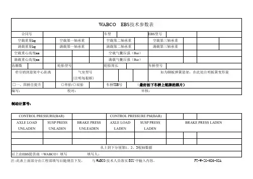
□一、四桥自提升
○单胎/○双胎
车桥TDB号
(最好拍下车桥上铭牌的照片)
编写: 校对:审核:
制动计算号:
CONTROL PRESSURE(BAR)
CONTROL PRESSURE PM(BAR)
AXLE LOAD UNLADEN
SUSP PRESS UNLADEN
WABCO EBS技术参数表
合同号
车型
EBS型号
空载重量kg
空载第一轴承重
空载第二轴承重
空载第三轴承重
满载重量kg
满载第一轴承重
满载第二轴承重
满载第三轴承重
空载重心高度mm
空载气囊压强(Bar)
满载重心高度mm
满载气囊压强(Bar)
齿圈数
轮胎型号
轮胎周长
车桥型号
牵引销到悬架中心距离
气室型号
(注明每根桥)
BRAKE PRESS UNLEADEN
AXLE LOAD LADEN
SUSP PRESS LADEN
BRAKE PRESS LADEN
从上到下分别第1、2、3根轴数据
以上由EBS提供商(WABCO)填写填写人:
注:此表上面部分由工程部填写后随规范下发, 与WABCO技术人员落实ECU中输入内容。FT-W-ZG-H26-02A
ECAS-空气悬架知识介绍
紧凑式ECAS。
2001年:批量生产新一代电磁阀(ECAS III,取代 ECAS I)和新一代ECU (ECAS CAN 2)。
15032002.ppt/D.M. G. Meise
88
48
1999年:开始生产ELM,一种将高度传感器集合在一个模块中的主要用于挂车的
汽
1999年:开始研制新一代的被称为“ECAS CAN2”的ECU。
学
苑
4
WABCO
Vehicle Control Systems
ECAS开发过程和客户
15032002.ppt/D.M. G. Meise
DC
88
MAN
48
汽
DAF Scania Iveco
5
车
学
RVI
苑
Kässbohrer
WABCO
Vehicle Control Systems
15032002.ppt/D.M. G. Meise
常规客车空气悬挂系统(带kneeling 功能)
88
ECAS 优 点 举 例
15032002.ppt/D.M. G. Meise
14
48
汽
车
学
苑
WABCO
Vehicle Control Systems
苑 学 车
WS
4. 气囊 5. 遥控器
ECU
正常高度
MV
1 5 3
2
1. 电子控制器 (ECU) 2. 电磁阀 3. 高度传感器
15032002.ppt/D.M. G. Meise
88
3.高度传感器
48
电磁阀通常安装在车架或车架横梁上。ECAS电磁阀是高度集成化和模块化的设 计。取决于不同的配置,在通用的外部壳体内可以布置不同数量的电磁阀部件。 ECAS组合电磁阀可大大节省了零部件数量和安装空间以及装配费用。为了降低排气 噪声,电磁阀排气口带有消音器。
WABCO传动系统(1)
Nov.12
便捷的维修
18
WABCO离合器控制系统价值
使用WABCO离合器助力缸的益处 更长的免维护寿命 => 成本降低: 成本降低 WABCO: 大于2,000,000 次正常使用寿命 免维护系统=>无需初调,自动磨损补偿=>减少日常维护工作量 => 成本降低; 成本降低 磨损指示功能=>直接显示离合器片的磨损状况=>减少日常维护工 作量 => 成本降低; 高的可靠性=>避免离合器和变速器同步器、齿轮的异常磨损,延 长了离合器和变速器的寿命=> 成本降低; WABCO 可以提供完整的离合器控制系统解决方案; 目前,中国的卡车和客车出口市场在不断的发展,匹配WABCO离合器 控制系统可以更大程度的满足全世界客户的需要和期望。
集成ECU的模块 化AMT系统 AMT新一代 ECU 新一代换档 手柄单元与 优化的组件 第一台AMT 在美国市场 应用 1995 GS1 1996 EPS2 1999 Sure Shift 2000 GS3 带拨叉的全集 成化AMT系统 2002 I-Shift 2003 EPS3 2004 AGS2 2008 NM-AMT 2010 新模块化AMT 系统进入中国
Nov.12
方便的磨损指示功能
17
离合器助力缸维护和维修工具包
■ 离合器助力缸的维护 − 正常使用时,威伯科离合器助力缸不 需要任何维护,除了需在车辆维护时 检查制动液液面以及踏板力的大小是 否正常。 − 三年或九十万公里后,建议使用对应 的维修工具包,根据说明更换助力缸 内全部的橡胶件和润滑油 − 制动液须每两年或三十万公里更换一 次. ■ 威伯科提供离合器助力缸的维修工具包, 其内有各种橡胶件、密封件的备件。 ■ 一旦出现了密封失效的故障,经过检查, 可以通过清洁相关部件后更换橡胶密封件 的方式得以解决,有效的降低维护成本。
WABCO 盘式制动器说明
磨损指示传感器安装在制动衬块底 板上,传感器头部是一个线圈,把 线圈固定到合适的位置。 可以提供两个信号: 1-当线圈接触制动盘时 2- 当线圈磨穿时 这样就可以提供预先报警信号。
WABCO Confidential and Proprietary
电子磨损指示功能
电线支撑板
剩余厚度 2 mm 可磨损厚度
WABCO Confidential and Proprietary
商用车市场浮钳盘制动器的技术趋势
亚洲 日本 - 楔块式制动或者盘式制动器正在取代S凸轮鼓式制动器 - 总重小于15 t的车辆使用液压盘式制动器 中国 - 空气式盘式制动器取代S凸轮鼓式制动器 - 系统/模块供应
WABCO Confidential and Proprietary
更换时间
鼓式制动器
拆卸车轮 (10min.) 拆除制动鼓 拆除制动蹄片等等 (共10min.) 安装新零件 (10min.) 加工制动片 (15min.) 安装车轮 (10min.) 时间: 55 分钟/车轮
盘式制动器
拆卸车轮 (10min.) 拆卸固定弹簧 拆卸制动衬片 安装新零件 (共 6min.) 安装车轮 (10min.)
3
1
WABCO Confidential and Proprietary
推杆密封
双推杆
密封
WABCO Confidential and Proprietary
单推杆
可降低温度100°C ! 推盘可以减少传递到密封圈的热量
电子式磨损指示器
不管制动盘的厚度是多少,有电子磨损指示器的帮助,可以保证制动衬块 磨损到2mm才进行更换,从而避免损坏制动盘。
零件数量更少, 可靠性更高
WABCO ECAS系统 培训
前轴
后桥
前后桥均为空气悬挂的4×2车系统布置
15032002.ppt/D.M. G. Meise
17
Vehicle Control Systems
pair-suspension
ECU 446 055 50. 0
指
标 高 度 的 控 制。 正 常 高 度 I/II。 用 开 关 / 按 键 进 行 手 动 高 度 调 节。 Kneeling。 监 视 供 气 压 力,如 只 有 特 定 的 环 境 下 允 许 Kneeling。 借 助 压 力 传 感 器 对 轴 荷 进 检 测。 35 Pin ECU
ECAS 附 加 优 点
15032002.ppt/D.M. G. Meise
7
Vehicle Control Systems
常规客车空气悬挂系统(带kneeling 功能)
ECAS 优 点 举 例
15032002.ppt/D.M. G. Meise
8
Vehicle Control Systems
5
Vehicle Control Systems
ECAS - Electronically Controlled Air Suspension
系 统 部 件
15032002.ppt/D.M. G. Meise
6
Vehicle Control Systems
ECAS 的 优 点 :
15032002.ppt/D.M. G. Meise
12
Vehicle Control Systems
Main Customers
WABCO ECAS Systems Sold World - Wide