IP-ASI适配器RTP说明书
isysNet EtherNet IP 适配器,Series A(PSSCENA)用户手册说明书
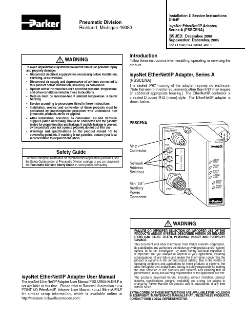
IntroductionFollow these instructions when installing, operating, or servicing the product.isysNet EtherNet/IP Adapter, Series A(PSSCENA)The sealed IP67 housing of the adapter requires no enclosure. (Note that environmental requirements other than IP67 may require an additional appropriate housing.) The EtherNet/IP connector is a sealed D-coded M12 (micro) style. The EtherNet/IP adapter is shown below.Installation & Service Instructions E104PisysNet EtherNet/IP Adapter, Series A (PSSCENA)ISSUED: December, 2006 Supersedes: December, 2005Doc.# E104P, EN# 060961, Rev. 3Pneumatic DivisionRichland, Michigan 49083isysNet EtherNet/IP Adapter User ManualThe isysNet EtherNet/IP Adapter User Manual PSS-UM004A-EN-P is not available at this time. Please refer to Rockwell Automation 1734 POINT I/O EtherNet/IP Adapter User Manual 1734-UM011A-EN-P for similar setup information, which is available online at /.WARNINGFAILURE OR IMPROPER SELECTION OR IMPROPER USE OF THE PRODUCTS AND/OR SYSTEMS DESCRIBED HEREIN OR RELATED ITEMS CAN CAUSE DEATH, PERSONAL INJURY AND PROPERTY DAMAGE.This document and other information from Parker Hannifin Corporation, its subsidiaries and authorized distributors provide product and/or system options for further investigation by users having technical expertise. It is important that you analyze all aspects of your application, including consequences of any failure and review the information concerning the product or systems in the current product catalog. Due to the variety of operating conditions and applications for these products or systems, the user, through its own analysis and testing, is solely responsible for making the final selection of the products and systems and assuring that all performance, safety and warning requirements of the application are met.The products described herein, including without limitation, product features, specifications, designs, availability and pricing, are subject to change by Parker Hannifin Corporation and its subsidiaries at any time without notice.EXTRA COPIES OF THESE INSTRUCTIONS ARE AVAILABLE FOR INCLUSION IN EQUIPMENT / MAINTENANCE MANUALS THAT UTILIZE THESE PRODUCTS. CONTACT YOUR LOCAL REPRESENTATIVE.!Safety GuideFor more complete information on recommended application guidelines, see the Safety Guide section of Pneumatic Division catalogs or you can download the Pneumatic Division Safety Guide at: /safetyWARNINGTo avoid unpredictable system behavior that can cause personal injury and property damage:• Disconnect electrical supply (when necessary) before installation, servicing, or conversion.• Disconnect air supply and depressurize all air lines connected to this product before installation, servicing, or conversion.• Operate within the manufacturer’s specified pressure, temperature, and other conditions listed in these instructions.• Medium must be moisture-free if ambient temperature is below freezing.• Service according to procedures listed in these instructions.• Installation, service, and conversion of these products must be performed by knowledgeable personnel who understand how pneumatic products are to be applied.• After installation, servicing, or conversion, air and electrical supplies (when necessary) should be connected and the product tested for proper function and leakage. If audible leakage is present, or the product does not operate properly, do not put into use.• Warnings and specifications on the product should not be covered by paint, etc. If masking is not possible, contact your local representative for replacement labels.!isysNet EtherNet/IP Adapter, Series A (PSSCENA) E104P2Important User InformationSolid state equipment has operational characteristics differing from those of electromechanical equipment. Safety Guidelines for the Application, Installation and Maintenance of Solid State Controls (available online at /pneu/isysNet) describes some important differences between solid state equipment and hard-wired electromechanical devices. Because of this difference, and also because of the wide variety of uses for solid state equipment, all persons responsible for applying this equipment must satisfy themselves that each intended application of this equipment is acceptable.In no event will Parker Hannifin Corporation be responsible or liable for indirect or consequential damages resulting from the use or application of this equipment.The examples and diagrams in this manual are included solely for illustrative purposes. Because of the many variables and requirements associated with any particular installation, Parker Hannifin Corporation cannot assume responsibility or liability for actual use based on the examples and diagrams.No patent liability is assumed by Parker Hannifin Corporation with respect to use of information, circuits, equipment, or software described in this manual.Reproduction of the contents of this manual, in whole or in part, without written permission of Parker Hannifin Corporation is prohibited.Throughout this manual we use notes to make you aware of safety considerations.isysNet EtherNet/IP Adapter, Series A (PSSCENA) E104P3Mount the Adapter and I/O BaseT o mount the adapter on a wall or panel, use the screw holes provided in the adapter.A mounting illustration for the adapter with I/O bases is shown below.(137.0)for M4 Screw(76.6)for M6 ScrewInstall the Mounting Base as Follows:1. Lay out the required points as shown above in the drillingdimension drawing.2. Drill the necessary holes for #8 (M4) machine or self-tappingscrews.3. Mount the adapter using #8 (M4) screws.4. Ground the system using the ground lug connection in the I/Obase. (The ground lug connection is also a mounting hole.)Before You BeginT o effectively use your adapter, note the following considerations.Determine CompatibilityIf using the adapter with an Allen-Bradley 1756-ENBT module or 1788-ENBT module, use the following required firmware versions for these bridge modules:• 1756-ENBT firmware version 2.3 or greater • 1788-ENBT firmware version 1.33 or greaterIf you use the BootP Utility to assign IP addresses to the adapter, use version 2.3.2 or greater.Understanding MessagingClass 3 (Explicit Message) requests through the adapter to a specific I/O module may not always receive a response from the I/O module. In the case where the I/O module does not reply to the request, the adapter responds with an error code indicating a time-out.Establish I/O ConnectionsWhen you power up an isysNet I/O system and establish I/O connections, the outputs transition to the Idle state, applying Idle state data before going to RUN mode. This occurs even when the controller making the connection is already in RUN mode.Configure AutobaudThe adapter cannot reconfigure an I/O module that you previously configured to operate at a fixed baud rate. When you reuse an isysNet I/O module from another isysNet I/O system, configure the module to autobaud before using it with the adapter.Open Configuration MethodFor using isysNet EtherNet/IP Adapters without RSNetWorx™ or RSLogix™ 5000, refer to document “User Guide: Configuration of the isysNet™ Pneumatics Platform using Explicit Messaging", which is available at /pneu/isysnet.* Depending on the type and number of manifolds, this dimension may vary. Refer to Catalog 0600P-# for additional information.GroundingEach isysNet base has two mounting holes, with the one on the right being the means to ground each module. Each module must be grounded.Set the Network AddressT o set the network address, you can:• Adjust the switches on the front of the module• Use a Dynamic Host Configuration Protocol (DHCP) server • Retrieve the IP address from nonvolatile memoryThe adapter reads the switches first to determine if the switches are set to a valid number. Y ou set the node address by adjusting the 3 switches on the front of the module (refer to the illustration on page 1). Use a small blade screwdriver to rotate the switches. Line up the small notch on the switch with the number setting you wish to use. Valid settings range from 001 through 254.will be 192.168.1.xxx (where xxx represents the number set on the switches). The adapter’s subnet mask will be 255.255.255.0 and the gateway address will be set to 0.0.0.0. When the adapter is readingthe network address set on the switches, the adapter will not have a host name assigned to it or use any Domain Name System.If the switches are set to an invalid number(i.e., 000 or a value greater than 254), the adapter checks to see if DHCP is enabled. If DHCP is enabled, the adapter asks for an address from a DHCP server. The DHCP server will also assign other T ransport Control Protocol (TCP) parameters.If DHCP is not enabled, the adapter will use the IP address (along with other TCP configurable parameters) stored in nonvolatile memory.EDS File RequirementsThe EDS file is available online at /pneu/isysNet.isysNet EtherNet/IP Adapter, Series A (PSSCENA) E104P4This example shows the network address set at 163.Add EtherNet/IP Adapter to RSLogix 5000 I/O ConfigurationT o add your PSSCENA to RSLogix 5000 I/O configuration, follow these steps:• In RSLogix 5000, highlight the EtherNet/IP Scanner , right clickand select New Module .If your RSLogic 5000 is Version 15.X or greater:• Choose the PSSCENA module from the list of Parker modules.• Enter a name, an appropriate I/P address and chassis size.• Choose Next to set RPI .• Choose Finish . Notice that the PSSCENA is now under the I/Oconfiguration.If your RSLogic 5000 is Version 13.X:• Choose the 1738-AENT/A from the list of modules.• Enter a name, an appropriate IP address, and chassis size. Makesure to choose Compatible Module for Electronic Keying setting.• Choose Next to set RPI.• Choose Finish . Notice that the 1738-AENT is now under theI/O configurationisysNet EtherNet/IP Adapter, Series A (PSSCENA) E104P5Wire the EtherNet/IP AdapterFollowing are wiring instructions for the EtherNet/IP Adapter.Female In ConnectorPSSCENA Network Connector (D-Coded M12)(view into connector)Pin 1 - Tx +Pin 2 - Rx +Pin 3 - Tx -Pin 4 - Rx -Male In ConnectorPSSCENA Auxiliary Power (Mini 7/8")(view into connector)Pin 1 - User Power +Pin 2 - Adapter Power +Pin 3 - Adapter Power -Pin 4 - User Power -NOTE: User power is the 24VDC power for field devices.Adapter power is the 24VDC power for adapter. It is converted to 5VDC to power isysNet modules.isysNet EtherNet/IP Adapter, Series A (PSSCENA) E104P6Troubleshoot with the IndicatorsPSSCENAAdapter Status Indicator Network Activity Indicator Network Status Indicator PointBus Status Indicator System Power Indicator Adapter Power IndicatorIndicationProbable CauseAdapter Status OffNo power applied to deviceFlashing Red/Green LED power up test (module self-test)GreenDevice is operating normally Flashing Red Recoverable fault has occurred: - Firmware (NVS) update- Network IP address changed- CPU load exceededSolid Red Unrecoverable fault has occurred: - Self-test failure (checksum failure at power up, ramtest) failure at power up- Firmware fatal error IndicationProbable CauseNetwork Activity OffNo link establishedFlashing Green/Off T ransmit or receive activity GreenLink established IndicationProbable CauseNetwork Status Off Device is not initialized. The moduledoes not have an IP address.Flashing Green No CIP connections. Device has an IP address, but no CIP connections areestablished.Green CIP connections. Device on line, has an IP address, and CIP connections areestablished.Flashing Red One or more Ethernet ® connections has timed out.Red No link. The module is not physically connected to a powered Ethernetdevice.Flashing Red/Green The module is performing a self test(only occurs during power up test).IndicationProbable CausePointBus Status Off Device not powered -check module status indicator Flashing Red/Green Recoverable fault has occurred: - At power up the number ofexpected modules does not equal the number of modules present - A module is missing- Node fault (I/O connection timeout)Red Unrecoverable fault has occurred: - The adapter is bus off- Controller in program/idle mode- Ethernet cable openGreen Adapter is on line with connections established (normal operation,run mode)IndicationProbable CauseSystem Power*Off Not active - Field power is off, overloaded backplane or dc-dcconverter problemGreen System power on - dc-dc converteractive (5V)IndicationProbable CauseAdapter Power**Off Not active - Field power is off GreenPower on - 24V present* System Power Indicator shows the 5V power output from the dc-dc converter.** Adapter Power Indicator shows the 24V power input to the dc-dc converter.isysNet EtherNet/IP Adapter, Series A (PSSCENA) E104P SpecificationsFollowing are specifications for the PSSCENA EtherNet/IP adapter.EtherNet/IP Adapter - PSSCENAExpansion I/O Capacity • Maximum of 63 modules• Maximum of 5 Rack Optimized connections (for digital modules only)• Maximum of 25 Direct connections• PSSCENA backplane current output = 1.0A maximum. The actual number of modulescan vary. Add up the current requirements of the modules you want to use to make surethey do not exceed the amperage limit of 1.0A for the PSSCENA.• Backplane current can be extended beyond 1.0A with a PSSSE24A Backplane ExtensionPower Supply. Add multiple PSSSE24A modules to reach the 63 module maximum.Cat. No. PointBus Current RequirementsPSSN8xxx 75 mAPSSP8xxx 75 mAPSST8xxx 75 mAPSSTR4M12A 90 mAPSSNACM12A 75 mAPSSNAVM12A 75 mAPSST ACM12A 75 mAPSST AVM12A 75 mAPSSS23A 75 mAPSSV32A 75 mAEtherNet/IP Communication Rate 10/100Mbits /s, half or full-duplexPower Supply SpecificationsPower Supply Note: In order to comply with CE Low Voltage Directives (LVD), you must use either aNEC Class 2, a Safety Extra Low Voltage (SELV) or a Protected Extra Low Voltage (PELV)power supply to power this adapter. A SELV supply cannot exceed 30V rms, 42.4V peakor 60VDC under normal conditions and under single fault conditions. A PELV supply hasthe same rating and is connected to protected earth.Input Voltage Rating 24VDC nominal10-28.8VDC rangeInrush Current 6A maximum for 10msField Side Power Requirements, Maximum 24VDC (+20% = 28.8VDC) @ 400 mAInterruption Output voltage will stay within specifications when input drops out for10ms at 10V with maximum loadGeneral SpecificationsLED Indicators 1 green/red Adapter status1 green Network activity1 green/red Network status1 green/red PointBus status1 green System Power (PointBus 5V power)1 green Adapter Power (24V from field supply)Power Consumption, Maximum ************Power Dissipation, Maximum ************Thermal Dissipation, Maximum 9.5BTU/***********PointBus Output Current, Maximum 1A @ 5VDC ±5% (4.75 - 5.25)Input Overvoltage Protection Reverse polarity protectedIsolation Voltage 50V rms(continuous-voltage withstand rating) Tested to withstand 1250VAC rms for 60sField Power BusNominal Voltage 24VDCSupply Voltage 10-28.8VDC rangeSupply Current 10A maximumDimensions Inches (Millimeters) 4.41H x 2.83W x 2.56D (112H x 72W x 65D)7isysNet EtherNet/IP Adapter, Series A (PSSCENA) E104PGeneral Specifications (continued)Operating Temperature IEC 60068-2-1 (T est Ad, Operating Cold),IEC 60068-2-2 (T est Bd, Operating Dry Heat),IEC 60068-2-14 (Test Nb, Operating Thermal Shock):-20 to 60°C (-4 to 140°F)Storage Temperature IEC 60068-2-1 (Test Ab, Un-packaged Non-operating Cold),IEC 60068-2-2 (T est Bb, Un-packaged Non-operating Dry Heat),-40 to 85°C (-40 to 185°F)Relative Humidity IEC 60068-2-30 (Test Db, Un-packaged Non-operating Damp Heat):5-95% non-condensingShock IEC60068-2-27 (T est Ea, Unpackaged Shock):Operating 30gNon-operating 50gVibration IEC60068-2-6 (T est Fc, Operating):5g @ 10-500HzESD Immunity IEC 61000-4-2:6kV contact discharges8kV air dischargesRadiated RF Immunity IEC 61000-4-3:10V/m with 1kHz sine-wave 80%AM from 30MHz to 2000MHz10V/m with 200Hz 50% Pulse 100%AM at 900Mhz10V/m with 200Hz 50% Pulse 100%AM at 1890MhzEFT/B Immunity IEC 61000-4-4:±4kV at 5kHz on power ports±2kV at 5kHz on communications portsSurge T ransient Immunity IEC 61000-4-5:±1kV line-line(DM) and ±2kV line-earth(CM) on power ports±2kV line-earth(CM) on unshielded communications port (tested as balanced circuits) Conducted RF Immunity IEC 61000-4-6:10Vrms with 1kHz sine-wave 80%AM from 150kHz to 80MHzEmissions CSPR 11:Group 1, Class AEnclosure T ype Rating Meets IP65/66/67 (when marked)Mounting Base Screw T orque #8 screw, 7.5 in. lbs. in Aluminum, 16 in. lbs. in SteelWiring Category1 1 - on power ports1 - on communications portsWeight Imperial (Metric) 0.80 lb. (0.36 kg)Certifications: (when product is marked) c-UL-us UL Listed Industrial Control Equipment, certified for US and CanadaCE European Union 89/336/EEC EMC Directive, compliant with:EN 61000-6-4; Industrial EmissionsEN 50082-2; Industrial ImmunityEN 61326; Meas./Control/Lab., Industrial RequirementsEN 61000-6-2; Industrial ImmunityC-Tick Australian Radiocommunications Act, compliant with:AS/NZS CISPR 11; Industrial EmissionsEtherNet/IP ODVA conformance tested to EtherNet/IP specifications1. Use this Conductor Category information for planning conductor routing. Refer to Publication E115P, “Industrial Automation Wiring andGrounding Guidelines”.8。
IP-ASI适配器RTP说明书

IP-ASI适配器RTP说明书IP/RTP->ASI⽹关使⽤说明书⽬录1安全注意事项 (2)2概述 (3)2.1产品功能及⽤途 (3)2.2外形尺⼨(1U机箱) (3)3主要特点 (4)4技术规格与指标 (4)4.1数据接⼝ (4)4.1.1IP数据接⼝ (4)4.1.2ASI输出接⼝ (4)4.2⽹管接⼝ (5)4.3辐射及安全要求 (5)5系统组成及⼯作原理 (5)5.1系统组成 (5)5.2⼯作原理 (7)6安装指南 (7)6.1安装准备 (7)6.2设备安装流程 (7)6.3环境条件要求 (8)6.4接地要求 (8)6.4.1机柜接地 (9)6.4.2设备接地 (9)6.5线缆的连接 (9)6.5.1电源线的连接 (9)6.5.2信号线的连接 (9)7前⾯板操作指南 (10)7.2菜单选择 (10)7.2.1锁定状态显⽰ (10)7.2.2主菜单显⽰ (10)7.2.3基本参数设置 (11)7.2.4⽹络设置 (13)7.2.5保存当前设置 (14)7.2.6加载设置 (14)7.2.7版本号 (14)7.2.8选择语⾔种类(中⽂和英⽂) (15)7.2.9错误信息 (15)7.2.1常见故障排除 (15)7.3系统运⾏错误及排除 (15)7.3.1指⽰灯状态 (15)8⽹络管理器操作指南 (16)8.1NMS登陆 (16)8.2添加频点 (18)8.3添加设备 (18)8.4修改设备 (19)8.5查看和设置设备参数 (22)8.5.1TS IP⽹关 (23)8.6⽹管软件公共功能 (23)前⾔感谢您选⽤本公司的产品。
本⼿册详细介绍了产品的性能、安装及操作⽅法,⽆论您是第⼀次使⽤该产品,还是以前接触过很多类似产品,都必须在使⽤前仔细阅读本⼿册。
收货检查打开设备包装箱校验物品,务必检查⼩部件的包装材料,对照产品装箱清单或者下列项⽬检查包装箱中的物品:IP/RTP->ASI ⽹关 1台交流输⼊电源插线 1根ASI线 2根如果这些项⽬与清单不符合,请⽴即通知我公司。
KuVision柯维新统计复用器说明书

1.电源指示灯2.方向按键及中间确认按键3.返回键统计复用器正面数据网口ASI 输入口ASI 输出口统计复用器背面远程控制网口按确认键1.设备配置按确认键2.设备状态3.系统时间按确认键1.设备配置按确认键2.设备状态3.系统时间按确认键选择要配置的网口,按确认键按确定键可选择自动/手动IP 模式手动设置IP 地址,上下键选择数字,左右键移动光标,按确定键修改。
手动设置网关地址,上下键选择数字,左右键移动光标,按确定键修改。
自动手动将设备网管端口连至电脑,设置电脑IP与编码器网管口IP同一网段,然后在WEB端输入编码器网管口IP地址,进入WEB配置界面。
在浏览器地址栏输入IP地址,按回车打开全部展开/全部闭合Licese :为授权的信息System :系统工具Network Setting :网络设置Network (1-4):指4个网口Debug Out Setting :排错设置System Status :系统工作状态FirmwareUpdate :软件升级,日志和配置的导出导入System Version:系统版本Kernel Version:核心版本License Valid:是否授权Support StatMuxer:是否支持统计复用Max Mux Pool Count:统计复用池个数Max Stream Count Per Pool:统计复用池最大输入码流数Clear Alarm Log:清空Alarm日志Clear Debug Log :清空Debug日志Reboot:重启Factory Reset:恢复出厂设置选择IP模式,点击可更改自动或手动模式。
自动模式手动模式手动模式下可以手动设置IP地址与网关地址。
此处选项为排错信息输出设置,信息是以单播形式发送,Enable 默认值为No ,是关闭的。
电源工作状态更新版本导入参数配置导出Debug 日志文件更新授权文件导出授权文件导出ALARM 日志文件导出参数配置运行“StatMuxerRemoteControlPanel.exe”程序,打开客户端程序统计复用的版本号启动客户端后,输入统计复用的IP地址,点击连接按钮添加复用池此处显示客户端连接状态输入统计复用池名称,然后点击“添加按钮”复用池名称添加或者删除复用池添加输入源,选择源类型后,点击添加按钮除了支持复用KuVision 的编码器,还支持复用UDP,ASI,RTP 的码流添加编码器输入编码器连接复用器的网口的IP 地址添加UDP 码流在“编码器IP”栏输入需要统计复用的设备的IP 地址,再单击“添加”按钮。
IP 系列单相逆变器操作说明书
IP系列单相逆变器操作说明书迅昌电气(上海)有限公司CINTRONG ELECTRICITY(SHANGHAI)CO.,LTD.苏州迅昌电力电子有限公司SUZHOU CINTRONG POWER ELECTRONICS CO.,LTD.重要提示:该设备符合以下参考标准IEC60950-1,IEC62040-1-1使用操作区一般安全IEC/EN62040-2EMC要求IEC62040-3性能要求和测试方法设备的安装应遵照以上要求并使用厂家指定附件。
本手册涉及IP工频逆变电源的相关安装与运行资料,请在安装前详细阅读本手册。
该设备内部有整流滤波电容,是储能元件,在关断输入交流电源后,直流部分可能仍有电压,请注意人身安全。
该设备安装有射频干扰(RFI)滤波器。
对地漏电流在3.5mA~1000mA之间。
在选择瞬变漏电流断路器(RCCB)或其它漏电检测仪器(RCD)时应考虑设备启动时可能出现的瞬态和稳态对地漏电流。
必须选择对单向直流脉冲(A级)和瞬态电流脉冲不敏感的RCCB。
请注意负载的对地漏电流也将流过RCCB或RCD。
目录1产品介绍 (1)1.1概述 (1)1.2设计思想 (1)1.3产品特点 (2)2搬运放置 (2)3使用环境 (2)4安装说明 (3)4.1初检 (3)4.1产品外形图 (3)5电气原理图(仅供参考) (4)6参数说明 (5)7电气连接 (5)8操作说明 (6)8.1准备开机 (6)8.2开机过程 (6)8.3关机过程 (6)9LCD说明 (6)9.1按键说明 (6)9.2参数显示 (7)10故障检修 (7)申明该手册仅适用于IP系列工频逆变电源产品,属通用版本。
技术指标详见技术合同或产品铭牌。
1产品介绍1.1概述IP工频逆变电源是迅昌公司采用ARM新一代32位处理器为核心,IGBT为执行元件,隔离变压器进行电压转换设计而成。
IP工频逆变电源采用DC-AC(直流-交流)的方式通过SPWM(正弦波脉宽调制)变换将输入电源转换成世界任何电源,以满足不同电压、不同频率的需要。
IP-ASI适配器UDP说明书

IP/UDP->ASI网关使用说明书目录1安全注意事项 (2)2概述 (3)2.1产品功能及用途 (3)2.2外形尺寸(1U机箱) (3)3主要特点 (4)4技术规格与指标 (4)4.1数据接口 (4)4.1.1IP数据接口 (4)4.1.2ASI输出接口 (4)4.2网管接口 (5)4.3辐射及安全要求 (5)5系统组成及工作原理 (5)5.1系统组成 (5)5.2工作原理 (7)6安装指南 (7)6.1安装准备 (7)6.2设备安装流程 (7)6.3环境条件要求 (8)6.4接地要求 (8)6.4.1机柜接地 (9)6.4.2设备接地 (9)6.5线缆的连接 (9)6.5.1电源线的连接 (9)6.5.2信号线的连接 (9)7前面板操作指南 (10)7.1键盘功能 (10)7.2菜单选择 (10)7.2.1锁定状态显示 (10)7.2.2主菜单显示 (10)7.2.3基本参数设置 (11)7.2.4网络设置 (13)7.2.5保存当前设置 (14)7.2.6加载设置 (14)7.2.7版本号 (14)7.2.8选择语言种类(中文和英文) (15)7.2.9错误信息 (15)7.3系统运行错误及排除 (15)7.3.1指示灯状态 (15)7.3.2常见故障排除 (15)8网络管理器操作指南 (16)8.1NMS登陆 (16)8.2添加频点 (18)8.3添加设备 (18)8.4修改设备 (19)8.5查看和设置设备参数 (22)8.5.1TS IP网关 (23)8.6网管软件公共功能 (23)前言感谢您选用本公司的产品。
本手册详细介绍了产品的性能、安装及操作方法,无论您是第一次使用该产品,还是以前接触过很多类似产品,都必须在使用前仔细阅读本手册。
收货检查打开设备包装箱校验物品,务必检查小部件的包装材料,对照产品装箱清单或者下列项目检查包装箱中的物品:IP/UDP->ASI 网关 1台交流输入电源插线 1根ASI线 2根如果这些项目与清单不符合,请立即通知我公司。
GM-2730M_使用说明书资料
多功能ASI-to-IP适配器GM-2730M使用说明书高斯贝尔数码科技股份有限公司安全须知在开启设备前一定要阅读使用说明书私自打开机盖可能造成对人体的伤害,并导致设备无法保修勿剧烈碰撞或从高处摔落本设备,这样的操作可能损坏设备内部硬件设备机箱内不得落入易燃物、金属物液体等,这些东西会损坏设备不要将设备安装在热源附近、阳光直射处、灰尘过多处或有机械振动的场所在操作时确保设备机箱后部的接地柱和大地相连请使用正确的外部接线端口与设备的网络接口相连请不要快速而频繁地开启和关闭电源,这样容易使半导体芯片产生损伤请顺着电源插座方向进行电源线插拔不要用湿手触摸电源插座,以免触电对带电设备进行操作前,请摘下指环、项链、手表、手链等装饰品。
因为金属物品接触到设备的电源与地时可能引起短路导致元器件损坏对机箱进行操作或接近电源工作前,请拔掉交流电源输入电缆只允许经培训合格的人员对设备进行带电操作和维护请保证设备在工作时有良好的通风环境,否则会导致设备因过热而发生损坏长期不使用本设备时,请一定要拔下电源插头目录安全须知 (2)目录 (3)§1 产品介绍 (5)§1.1 GM-2730M的功能 (5)§1.2 GM-2730M的主要技术特点 (5)§1.3 GM-2730M的前面板 (5)§1.4 GM-2730M的后面板 (6)§1.5 应用 (6)§2 使用前须知 (8)§2.1 设备要求 (8)§2.1.1 对相关数字电视设备的需求 (8)§2.1.2 对网络设备的需求 (8)§2.2 系统需求 (8)§3 设备使用 (9)§3.1 第一次使用:快速入门 (9)§3.2 GM-2730M的Web管理操作 (9)§3.2.1 登录 (10)§3.2.2 用户管理 (12)§3.2.2.1 创建新用户 (13)§3.2.2.2 修改已有账户信息 (14)§3.2.2.3 删除已有用户账户 (14)§3.2.3 系统基本参数设置 (15)§3.2.3.1 以太网参数设置 (15)§3.2.3.2 MAC地址设置 (16)§3.2.3.3 系统时间相关参数设置 (16)§3.2.4 系统基本参数设置 (17)§3.2.4.1 参数导入/导出/重置设置 (17)§3.2.4.2 参数备份/恢复 (20)§3.2.4.3 软件升级/备份 (20)§3.2.4.4 设备授权 (23)§3.2.4.5 设备控制 (23)§3.2.5 输入输出设置 (24)§3.2.5.1 TUNER参数查询与设置 ........................................ 错误!未定义书签。
阿布拉康网络转换器产品说明书

ALANC100014.6 x 3.4 x 3.5 mmRoHS/RoHS II CompliantMSL Level = 1Request Samples Check InventoryPart Number Insertion Loss(dB Max)Return Loss (dB Min) 1-100 MHz100-200MHz 1-40 MHz40 -200MHzALANC10001-EEB30.81.22514.5Part NumberInductance (uH Min) Leakage Inductance (uH ) Interwinding Capacitance (pF Max) DC Resistance (Ω Max) Hi Pot (VAC) Weight (g) Test Condition @100kHz, 0.1V, 0mA DC Bias@ 100KHz, 0.1V@ 100KHz, 0.2VPins 1-2 Pins 4-5 60 sec. Per Piece ALANC10001-EEB31500.5351.21.215000.228ALANC10001 series is RoHS/ RoHS II Compliant and Pb free. Moisture Sensitivity Level (MSL) – Level 1Applicable Standards: IEEE 802.3u and 802.3ab Operating Temperature: -40˚C ~ +85˚CStorage Condition: -40˚C ~ +85˚C (on board),• Uniform transformer windings • Fully automated production lines • Meets IEEE 802.3u and 802.3ab standards • Compatible with 10 BASE-T, 100 BASE-TX and 1000 BASE-T • Symmetric Orientation • Operating temperature range up to -40°C to +85°C •RoHS Compliant•1CT:1CT Transformer • Fast and gigabit Ethernet • Servers, switches and routers• IP cameras, surveillance, and phone • Access points• Industrial computers and robotics • Networking and communications • Broadcast video •Set top boxFeaturesElectrical Specifications @25ºCApplicationsALANC10001 4.6 x 3.4 x 3.5 mmRoHS/RoHS II CompliantMSL Level = 1Request Samples Check InventoryALANC10001 -Marking Method = Ink MarkingOperating Temp. D: -40°C ~ +85°CSchematic EB3Package Size E:6-Pin Packaging T: 2.0K pcs/reel B: BulkPart Identification Polarity MarkingALANC10001 4.6 x 3.4 x 3.5 mmRoHS/RoHS II CompliantMSL Level = 1Request Samples Check InventoryE: 6-pinDimensions: mmA B C 4.60 ±0.203.40 ±0.20 3.50 ±0.20Coplanarity 0.10 MAXMechanical SpecificationsRecommended Land PatternALANC10001 4.6 x 3.4 x 3.5 mmRoHS/RoHS II CompliantMSL Level = 1Request Samples Check Inventory6 - Pin EB3SchematicALANC10001 4.6 x 3.4 x 3.5 mmRoHS/RoHS II CompliantMSL Level = 1Request Samples Check InventoryZone Description Temperature Times 1 Preheat T SMIN ~ T SMAX 150°C ~ 200°C60 ~ 120 sec. 2 Reflow T L 217°C 60 ~ 150 sec. 3Peak heatT P 260°C20 ~ 40 sec. MAXReflow ProfileALANC100014.6 x 3.4 x 3.5 mmRoHS/RoHS II CompliantMSL Level = 1Request Samples Check InventoryTape and Reel: 2,000 pcs/reel Pieces Per Carton: 20,000 pcs Weight Per Carton: 6 kg (approx.)Dimensions of Carton:345 x 345 x 220 mmDimensions: mmA0 B0 W E F P0 P1 P2 D0 T K0 3.704.9012.00 1.75 5.50 4.00 8.00 2.00 1.50 0.40 3.70PackagingALANC10001 4.6 x 3.4 x 3.5 mmRequest Samples Check InventoryRoHS/RoHS II CompliantMSL Level = 1 Dimensions: mmATTENTION:Abracon LLC’s products are COTS – Commercial-Off-The-Shelf products; suitable for Commercial, Industrial and, where designated, Automotive Applications. Abracon’s products are not specifically designed for Military, Aviation, Aerospace, Life-dependent Medical applications or any application requiring high reliability where component failure could result in loss of life and/or property. For applications requiring high reliability and/or presenting an extreme operating environment, written consent and authorization from Abracon LLC is required. Please contact Abracon LLC for more information.。
Cisco SPA112 122系列电话适配器快速安装指南说明书

Quick Start GuideCisco SPA100 Series Analog Telephone AdaptersSPA112 Two Port Phone AdapterSPA122 ATA with RouterPackage Contents•Analog T elephone Adapter•Ethernet Cable•Power Adapter•Quick Start Guide•Product CD-ROMWelcomeThank you for choosing a Cisco SPA100 Series Analog T elephone Adapter. This product family includes the following models:•SPA112 Two-Port Phone Adapter: 2 FXS ports and 1 10/100 WAN port.•SPA122 ATA with Router: 2 FXS ports, 1 10/100 WAN port, 1 10/100 LAN port, and built-in router.This guide describes how to physically install the equipment and how to get started with the configuration.Before You Begin1Before you begin the installation, make sure that you have the following equipment and services:•An active Internet account and Voice over IP account•Ethernet cable to connect to your broadband network device•Phone to connect to your SPA112/122•Phone cable to connect your phone•Optional: Uninterruptible Power Supply (UPS) to provide backup power Product Features2Top Panel2Cisco SPA100 Series Analog Telephone AdaptersBack PanelFeature DescriptionReset Using a paperclip or similar object, press this buttonbriefly to restart the unit. Press and hold for 10seconds to restore the factory default settings.Phone 1, Phone2 (Gray)Connect to an analog phone, using an RJ-11 phone cable.Ethernet (Yellow) SPA122 Only Can be used to connect to a device on your network, such as a computer, using an Ethernet cable.Internet (Blue)Connect to a broadband network device (DSL orcable modem) or a network router, using an Ethernetcable.Power Connect to a power source, using the providedpower adapter.Cisco SPA100 Series Analog Telephone Adapters 34Cisco SPA100 Series Analog Telephone AdaptersConnecting the EquipmentN OTE For wall-mounting instructions, see Mounting the ATA, page 9.S TEP 1Connect one end of the provided Ethernet cable to the Internet(Blue) port. Connect the other end directly to your broadband network deviceConnect one end of a phone cable to the Phone 1 (Gray) port. Connect the other end to your analog phone or fax machine.S TEP 2Connect one end of another phone cable to another analog phoneor fax machine. Connect the other end to the Phone 2 (Gray) port.S TEP 3SPA 122 Only: Optionally, connect one end of an Ethernet networkcable to the ETHERNET (Yellow) port of the ATA. Connect the other end to a device on your network, such as a computer.S TEP 4Connect the provided power adapter to the Power port.3239795WANConfiguration and Management of the ATA 4You can use the web-based configuration utility to set up your ATA. You also can use the built-in Interactive Voice Response (IVR) system.Using the Web-Based Configuration UtilityS TEP1Connect your computer to the same subnet as the ATA. For example, if the AT A is connected to a LAN port on your router, alsoconnect your computer to a LAN port on your router.Note: On SPA122, you can connect your computer to theETHERNET (Yellow) port of the AT A.S TEP2Power on your computer.NOTE: Make sure your computer’s Ethernet adapter is set to obtainan IP address automatically. For more information, refer to the Helpfor your operating system.S TEP3Start a web browser on your computer.S TEP4In the Address bar, enter the IP address of the ATA.•SPA112: Use the ATA’s IVR or your router’s configuration utility to find the dynamically assigned IP address of the ATA. Forinformation about the IVR, see Using the IVR forAdministration, page6.•SPA122: In the Address bar, enter: 192.168.15.1Note: 192.168.15.1 is the default local IP address of the AT A.S TEP5T o log in for the first time, enter the default username, admin, and the default password, admin. The password is case sensitive.S TEP6E nter the Connection Type and settings required by your Internet Service Provider. Types include DHCP (the default option),Static IP, and PPPoE (required for most DSL service). Afterentering these settings, click Submit to establish yourInternet connection.S TEP7Use the menus to configure your settings, as needed. For more information, see the A TA Administration Guide. (Documentationlinks are provided in Where to Go From Here, page11.)Cisco SPA100 Series Analog Telephone Adapters 5Using the IVR for AdministrationAn IVR system is available to help you to configure and manage your AT A. You can use the telephone keypad to select options and to make your entries.T o access the IVR menu:S TEP1Connect an analog phone to the Phone port of the AT A.S TEP2Press the star key four times: ****S TEP3After the greeting plays, press the keys on the phone keypad to select your options.S TEP4Enter the code for the desired action. See the IVR Actions table for details.TIPS:•Enter the numbers slowly, listening for the audio confirmation before entering the next number.•After you select an option, press the # (pound) key.•T o exit the menu, hang up the telephone or enter 3948# to exit.•After entering a value, such as an IP address, press the # (pound) key to indicate that you have finished your selection. T o save the new setting, press 1. T o review the new setting, press 2. T o re-enter the new setting, press 3. T o cancel your entry and return to the main menu, press * (star). •While entering a value, you can cancel the changes by pressing the * (star) key twice within half a second. Be sure to press the key quickly, or the * will be treated as a decimal point entry.•If the menu is inactive for more than one minute, the ATA times out. You will need to re-enter the menu by pressing the star key four times: ****.Your settings take effect after you hang up the telephone or exit the IVR.The ATA may reboot at this time.•T o enter the decimal points in an IP address, press the * (star) key. For example, to enter the IP address 191.168.1.105, perform the following tasks:–Press these keys:191*168*1*105.–Press the# (pound) key to indicate that you have finished entering the IP address.–Press 1 to save the IP address or press the * (star) key to cancel your entry and return to the main menu.6Cisco SPA100 Series Analog Telephone AdaptersIVR ActionsChoices and InstructionsIVR Action MenuOptionEnter IVR Menu****Check Internet Connection100TypeSet Internet Connection Type101DHCP: 0Static IP: 1PPPoE: Press 2PPPoE, DHCP: Press 3DHCP, PPPoE: Press 4Check Internet IP Address110(WAN port)Set Static IP Address (WAN)111Enter the IP address by usingnumbers on the telephonekey pad. Use the * (star) keywhen entering a decimalpoint.Note: This option is availableonly after you choose StaticIP as the Internet ConnectionType, through option 101. Check Network Mask120Set Network Mask121T o enter the value, pressnumbers on the telephonekey pad. Press the *(star) keyto enter a decimal point.Note: This option is availableonly after you choose StaticIP as the Internet ConnectionType, through option 101. Check Gateway IP Address130Cisco SPA100 Series Analog Telephone Adapters7Set Gateway IP Address131T o enter the value, pressnumbers on the telephonekey pad. Press the *(star) keyto enter a decimal point.Note: This option is availableonly after you choose StaticIP as the Internet ConnectionType, through option 101. Check MAC Address140Check Firmware Version150Check Primary DNS ServerSetting160Set Primary DNS Server161T o enter the value, pressnumbers on the telephonekey pad. Press the *(star) keyto enter a decimal point.Note: This option is availableonly after you choose StaticIP as the Internet ConnectionType, through option 101. Check Internet web serverport170SPA122 only: Check LAN IPaddress (Ethernet port)210Announce Line 1 SIPTransport1910Set Line 1 SIP Transport 19110: UDP1: TCP2: TLSCheck Line 2 SIP Transport 1920Set Line 2 SIP Transport19210: UDP1: TCP2: TLSExit IVR3948Allow or prevent WAN access to the administration web server 79321: Enable0: DisableIVR Action MenuOptionChoices and Instructions8Cisco SPA100 Series Analog Telephone AdaptersCisco SPA100 Series Analog Telephone Adapters 9Mounting the ATAYou can place the AT A on a desktop or mount it on a wall.C AUTIONT o prevent the ATA from overheating, do not operate it in an area that exceeds an ambient temperature of 104°F (40°C).Desktop PlacementPlace the ATA on a flat surface near an electrical outlet.W ARNING Do not place anything on top of the ATA; excessive weightcould damage it.Wall MountingThe ATA has two wall-mount slots on the bottom panel. T o mount the ATA on a wall, you need mounting hardware (not included). Suggested hardware is illustrated (not true to scale).Factory Reset of Unit WARNING: All non-default settings will be lost. Thisincludes network and service provider data.73738RESET When prompted, press 1 to confirm, or press * (star) to cancel. After you hear “Option successful,” hang up the phone. The ATA reboots.Reboot of Voice System 732668REBOOTAfter you hear “Option successful,” hang up the phone. The ATA er Factory Reset of Unit WARNING: All user-changeable non-defaultsettings will be lost. This may include network and service provider data.877778When prompted, press 1 to confirm, or press * (star) to cancel. After you hear “Option successful,” hang up the phone. The ATA reboots.IVR ActionMenu Option Choices and Instructions 5Recommended hardware (not included): Two number-six pan-head tapping screws, 5/8-in. length, with anchors for sheet rock installation.5/8 in. (15.8 mm)W ARNING Insecure mounting might damage the ATA or cause injury. Cisco is not responsible for damages incurred by insecure wall-mounting.T o mount the unit to the wall:S TEP1Determine where you want to mount the unit. Verify that the surface is smooth, flat, dry, and sturdy.S TEP2Drill two pilot holes into the surface 58mm apart (about 2.28 in.).S TEP3Insert a screw into each hole, leaving a gap of 5mm (0.1968 in.) between the underside of each screw head and the surface of thewall.S TEP4Place the unit wall-mount slots over the screws and slide the unit down until the screws fit snugly into the wall-mount slots.10Cisco SPA100 Series Analog Telephone AdaptersWhere to Go From HereSupportCisco Small BusinessSupport Community/go/smallbizsupportCisco Small BusinessSupport and Resources/go/smallbizhelp Phone Support Contacts /go/sbscCisco Small BusinessFirmware Downloads/go/softwareCisco Small Business Open Source Requests /go/smallbiz_opensource_ requestProduct DocumentationCisco Small BusinessAnalog T elephoneAdapters/go/smallbizvoicegatewaysCisco Small BusinessCisco Partner Centralfor Small Business(Partner Login Required)/web/partners/sell/smbCisco Small Business Home /smb6Cisco SPA100 Series Analog Telephone Adapters11Americas HeadquartersCisco Systems, Inc.170 West T asman DriveSan Jose, CA 95134-1706USASmall Business Support, Global: /go/sbsc78-19933-01 Cisco and the Cisco Logo are trademarks of Cisco Systems, Inc. and/or its affiliates in the U.S. and other countries. A listing of Cisco's trademarks can be found at /go/ trademarks. Third party trademarks mentioned are the property of their respective owners. The use of the word partner does not imply a partnership relationship between Cisco and any other company. (1005R)© 2011 Cisco Systems, Inc. All rights reserved.。
- 1、下载文档前请自行甄别文档内容的完整性,平台不提供额外的编辑、内容补充、找答案等附加服务。
- 2、"仅部分预览"的文档,不可在线预览部分如存在完整性等问题,可反馈申请退款(可完整预览的文档不适用该条件!)。
- 3、如文档侵犯您的权益,请联系客服反馈,我们会尽快为您处理(人工客服工作时间:9:00-18:30)。
IP/RTP->ASI网关使用说明书目录1安全注意事项 (2)2概述 (3)2.1产品功能及用途 (3)2.2外形尺寸(1U机箱) (3)3主要特点 (4)4技术规格与指标 (4)4.1数据接口 (4)4.1.1IP数据接口 (4)4.1.2ASI输出接口 (4)4.2网管接口 (5)4.3辐射及安全要求 (5)5系统组成及工作原理 (5)5.1系统组成 (5)5.2工作原理 (7)6安装指南 (7)6.1安装准备 (7)6.2设备安装流程 (7)6.3环境条件要求 (8)6.4接地要求 (8)6.4.1机柜接地 (9)6.4.2设备接地 (9)6.5线缆的连接 (9)6.5.1电源线的连接 (9)6.5.2信号线的连接 (9)7前面板操作指南 (10)7.1键盘功能 (10)7.2菜单选择 (10)7.2.1锁定状态显示 (10)7.2.2主菜单显示 (10)7.2.3基本参数设置 (11)7.2.4网络设置 (13)7.2.5保存当前设置 (14)7.2.6加载设置 (14)7.2.7版本号 (14)7.2.8选择语言种类(中文和英文) (15)7.2.9错误信息 (15)7.2.1常见故障排除 (15)7.3系统运行错误及排除 (15)7.3.1指示灯状态 (15)8网络管理器操作指南 (16)8.1NMS登陆 (16)8.2添加频点 (18)8.3添加设备 (18)8.4修改设备 (19)8.5查看和设置设备参数 (22)8.5.1TS IP网关 (23)8.6网管软件公共功能 (23)前言感谢您选用本公司的产品。
本手册详细介绍了产品的性能、安装及操作方法,无论您是第一次使用该产品,还是以前接触过很多类似产品,都必须在使用前仔细阅读本手册。
收货检查打开设备包装箱校验物品,务必检查小部件的包装材料,对照产品装箱清单或者下列项目检查包装箱中的物品:IP/RTP->ASI 网关 1台交流输入电源插线 1根ASI线 2根如果这些项目与清单不符合,请立即通知我公司。
阅读用户手册请仔细阅读用户手册,并遵从所有操作及其它说明事项。
1安全注意事项●在开启IP/RTP->ASI网关前一定要阅读使用说明书。
●绝对不要私自打开机盖,否则不予保修,另外触摸机内时有触电可能,十分危险。
●长期不使用IP/RTP->ASI网关时,请一定要拔下电源插头,另外请不要使用破坏的电源插座,以免发生火灾和触电。
●电源插座不要用湿手触摸,有触电的可能。
●拔掉连接导线时,应拔插头不要拉导线本身。
●机内不得落入易燃物、金属物、液体等,这些东西会损坏该装置。
●为了防止雷电引起的损坏,请在避雷装置场合下使用本设备,这样可有效防止雷电或电网波动造成损失。
●不要将IP/RTP->ASI网关安装在有散热或热空气管道等热源附近,也不要IP/RTP->ASI 网关安装在阳光直射处、灰尘过多处或有机械振动的场所。
●IP/RTP->ASI网关工作时,要有良好的通风环境,否则会损坏该设备。
●保存好原来的纸箱和包装材料,这样一旦需要搬运IP/RTP->ASI网关,可随手获得这些材料,按工厂的原包装方式包装可以获得最好防护。
2概述2.1产品功能及用途IP网关是有线数字电视前端的主要设备之一,接收来自编码器、复用器、DVB网关、加扰器、视频服务器等设备的DVB传输码流,转化为IP码流(UDP封装),或者接收来自于网络的码流,转化成ASI码流。
2.2外形尺寸(1U机箱)高:44mm宽:482mm深:280mm重:约4 Kg3主要特点●支持输入、输出信号的实时监测:●支持中英文液晶显示,前面板按键操作和远程网管控制: ●高可靠性设计,运行稳定:4技术规格与指标4.1数据接口4.1.1IP数据接口以太网接口:IEEE802.3以太网,RJ45接口软件协议:采用IP/RTP协议4.1.2ASI输出接口输入接口:1路DVB标准ASI接口连接器:BNC 阻抗:75传输流标准:ISO13818-1输入有效码率:最大214Mbps (每路) TS 包格式:188/204bytes (自动识别) TS 输入模式:均匀/包突发/不规则4.2 网管接口以太网接口:IEEE802.3以太网,RJ45接口 软件协议:采用IP/UDP 协议4.3 辐射及安全要求符合GB13837-92和GB8898-88标准。
5 系统组成及工作原理5.1 系统组成IP/RTP->ASI 网关 原理图如下:结构示意(1U机箱为例)前面板示意图后面板示意图5.2工作原理IP网关是有线数字电视前端的主要设备之一,接收来自编码器、复用器、DVB网关、加扰器、视频服务器等设备的DVB传输码流,转化为IP码流(RTP封装),或者接收来自于网络的码流,转化成ASI码流。
6安装指南6.1安装准备安装设备时,应按以下步骤:∙检查运输期间,可能发生的设备的丢失或损坏;∙准备装机的合适环境;∙安装IP/RTP->ASI网关;∙信号线的连接;设备安装时每个细节将在这一章的其余部分描述,具体的位置可参照后面板示意图。
6.2设备安装流程6.3环境条件要求6.4接地要求●各功能模块良好的地线设计是整机工作稳定,可靠的基础,是防雷击、抗干扰的首要保障。
因此系统接地必须遵循以上的原则;●同轴电缆的外导体和屏蔽层两端均应和所连接设备的金属机壳的外表面保持良好的电气接触;●接地线两端的连接点应确认电气接触良好,并应做防腐处理;●严禁利用其他设备作为接地线电气连通的组成部分;●机柜接至防雷单元的地线连接截面积必须大于或等于25mm2。
6.4.1机柜接地同一机房各机柜的接地端应分别接到局方提供的保护地铜排上,要求接地线尽量短,工程安装时如果接线过长,应截断,避免接地线盘绕。
接地端到地排上的导线截面积必须大于或等于25mm2。
6.4.2设备接地设备接地时,用导线将保护地接线柱连接到总装机柜的保护地线接排上。
6.5线缆的连接6.5.1电源线的连接●电源插孔位于后面板的右侧(从背面看),电源插孔的左面为电源开关,在电源插孔右侧为保护地线的连接螺钉。
●连接电源线:将电源线一端插入交流电源插孔,另一端连接交流电源。
连接地线:当单独接到机房中的保护地时,即采用独立接地的方式,即与其他设备(如传输设备)共同接地,联接地时的接地电阻小于16.5.2信号线的连接操作前,用户应该连接所有需要的电缆的装置。
7前面板操作指南7.1键盘功能左、右键:移动光标;上、下键:菜单翻页及参数修改;确认键(ENTER):进入子菜单及确认新参数更改;返回键(Exit ):返回上一级菜单或参数更改放弃。
注:A、在键盘锁定状态下,按任意键激活面板,然后先按确认键,再按返回键就可以解键盘锁,进入主菜单;B、在不操作键盘60秒钟后,键盘将自动锁定;C、在锁定状态下,按任意键激活面板,然后按上键可查看设备软硬件版本号、按下键可查看设备的IP地址、按左键可查看设备的MAC地址。
7.2菜单选择7.2.1锁定状态显示7.2.2主菜单显示初始化完成后,系统显示如下菜单:7.2.3 基本参数设置如果选择基本参数设置,系统显示如下菜单(按‘上下键’选择,然后按‘确认键’生效):按确定键(ENTER )进入各个菜单的下一级菜单如下:7.2.3.1 输出设置如果选择输出设置,按确定键(ENTER )进入各个菜单的下一级菜单如下(按‘上下键’选择,然后按‘确认键’生效):再次按‘确认键’,可进行数值更改,移动‘左右键’到想要更改的位置,按‘上下键’可更改值大小,改好之后,再次按‘确认键’使参数生效,若要取消设置,按‘返回键(Exit )’。
7.2.3.2输入设置如果选择输入设置,按确定键(ENTER)进入各个菜单的下一级菜单如下(按‘上下键’选择,然后按‘确认键’生效):再次按‘确认键’,可进行数值更改,移动‘左右键’到想要更改的位置,按‘上下键’可更改值大小,改好之后,再次按‘确认键’使参数生效,若要取消设置,按‘返回键(Exit )’。
7.2.3.3本地设置如果选择本地设置,系统显示如下菜单:再次按‘确认键’,可进行数值更改,移动‘左右键’到想要更改的位置,按‘上下键’可更改值大小,改好之后,再次按‘确认键’使参数生效,若要取消设置,按‘返回键(Exit )’。
7.2.4网络设置当用户选择此项设置后,系统显示如下菜单。
移动‘上下键’到要更改的选项,按‘确认键’进入改选项,再次按‘确认键’,可进行数值更改,移动‘左右键’到想要更改的位置,按‘上下键’可更改值大小,改好之后,再次按‘确认键’使参数生效,若要取消设置,按‘返回键(Exit )’。
7.2.5 保存当前设置选择此项设置后,按“Enter ”键直接进行保存,系统显示如下菜单:掉电状态保存可保存上次使用状态,在停电恢复后可以自行正确启动。
7.2.6 加载设置进入加载设置后,系统显示如下菜单(按‘上下键’选择,然后按‘确认键’生效),进行此操作之后不能重启设备,否则加载无效,重启设备之后,设备按之前保存的参数进行工作:7.2.7 版本号进入版本号菜单后,界面显示如下:7.2.8选择语言种类(中文和英文)进入语言选择菜单后,利用上、下方向按键选择语言种类。
默认值是中文显示界面,示意图如下(按‘上下键’选择,然后按‘确认键’生效):完成所有设置后,系统正常运行。
7.2.9错误信息进入错误信息菜单后,会显示设备是否工作正常,以及错误的信息,该选项会显示总错误信息数目,按‘上下键’可依次查看详细错误信息,示意图如下:7.2.1常见故障排除7.2.1.1“POWER”电源指示灯不亮请检查电源线是否插入电源插座内;电源开关是否处于接通位置。
7.2.1.2“ALARM”灯亮(红色)设备工作不正常,有故障报警,查看故障信息,并做相应处理。
7.3系统运行错误及排除7.3.1指示灯状态面板上有2个LED指示灯,分别表述如下。
1“POWER”为电源指示,当打开电源开关时,指示灯亮(绿色),表示设备电源工作正常。
2“ERROR”指示灯亮(红色),表示设备工作异常。
3“Lock”输入信号锁定8网络管理器操作指南网络管理器能够对该设备进行远程参数配置,状态监测。
但必须通过授权之后才能使用。
除了能通过设备的前面板操作设置设备参数以外,还可以用电脑设备通过网络管理软件()配置和监测设备的各项参数。
大部分的前端设备(卫星接收机,编码器,复用器,加扰机,调制器,网关等)都可以通过该NMS软件管理。
软件使用的通讯协议是UDP协议, 操作系统:Windows 系列。
8.1NMS登陆NMS登陆界面默认用户名和密码都为‘admin’。
可以通过‘设置’->‘用户配置’进行修改.登陆NMS 软件,如果是第一使用,还未添加任何设备信息,则显示如图:输入正确的用户名和密码后,点击“确认”登陆NMS软件。