万国奥西晒图机说明书
sBK1150一GM4晒版机使用手册

sBK1150一GM4晒版机使用手册一、工作原理:SB-型系列晒版机的晒版过程可能理解为:利用真空泵抽出室内空气,使室内形成真空负压迫使印版与稿件紧贴向玻璃平面,然后在预定的曝光时间内光源对印版感光层进行曝光,曝光结束自动放气晒版等过程来完成整个程序。
二、机械机构本机有电脑面板,机架,晒版架,真空装置,灯具,遮光保护帘,电器控制件等组成。
1. 电脑面板及说明:电源开关:通/断整机电源(1) 显示窗:三位显示晒版时间和执行过程。
(2) 曝光键:与数字键清零键组合使用,预置,查询,修改显示的主要曝光参数(3) 真空1键和真空2键:与数字键清零键组合使用,预置,查询,修改显示的一次抽气和二次抽气的延时时间。
调整真空1和真空2的时间组合,有利于消除抽气过程中的气泡,从而达到最佳的抽气效果。
(4) 数字键0-9:预置和修改参数时的键入数字。
(5)清零键: 预置和修改参数时,可用于显示器的清零。
(6)复位键: 将程序置为初始状态(即开机状态)2.机架整机采用箱式结构,内部铁皮钢管焊接而成,外表静电喷塑.从而保证了整机美观化.和稳定性长期使用。
3.晒版架该部分位于机架的上方。
通过铰链、阻尼器与机架连接成。
晒版机架压收紧时,玻璃和橡胶封垫形成一个供放版材的装夹的密闭室。
4.真空装置由真空泵,真空显示表,电磁阀和吸气管组成,其作用是抽出密闭室内的空气,提供合适负压。
5.灯具灯具在机架上方。
灯具是本机的核心部件,由高功率紫外线灯管,触发器,反光照装置,冷却风机、6.遮光保护帘防止紫外光光源外泄灼伤操作者,操作时请注意使用。
7.电器控制件与电脑面板组合使用,来实现整个程序的自动完成。
Master Manufacturing 15或25加仑地点喷洒器与拖车套装说明书

Boom Mounting 1.) Following directions provided with boom manufacturer, mount boom to boom brackets on trailer.
WARRANTY PARTS SERVICE Products sold shall be warranted from defects in workmanship and material when used within the service and scope for which they were designed for a period of one year from date of purchase. Contact your distributor/ dealer for replacements parts or warranty work. Please have your original sales receipt or other proof of purchase date when requesting any warranty work. To ensure the correct parts are acquired always provide the model number of your sprayer/attachment and the part number and description obtained from the illustrated parts breakdown in this manual.
晒图机的操作方法

晒图机的操作方法
1. 打开晒图机的电源开关,等待晒图机启动。
2. 准备要晒图的物品,将其放置在晒图机的工作台上。
3. 打开晒图机的控制面板,选择晒图的参数,如时间、温度等。
4. 将晒图机的活动台向下移动,使其与物品紧密接触。
5. 按下开始按钮,晒图机开始工作,根据设定的参数进行晒图。
6. 在晒图过程中,可以观察晒图机的显示屏上的进度,以确保晒图进程正常。
7. 晒图完成后,晒图机会发出提示音,关闭自动移动的活动台。
8. 打开晒图机的盖板,将晒图完成的物品取出。
9. 关闭晒图机的电源开关,结束晒图操作。
注意事项:
- 在操作晒图机时,需要注意安全,避免触摸热表面。
- 在选择参数时,需要根据物品的特性进行合理的设定,以保证晒图效果。
- 在更新晒图机的操作方法之前,请确保阅读并理解晒图机的用户手册,以确保安全操作和最佳效果。
奥图码投影机说书

使用注意事项......................................................................源自.................2
安全说明 ................................................................................................................................. 2
SC-2
8. 更换部件 当需要更换部件时,务必使用制造商指定的更换部件。未经授权的更换 可能导致火灾、触电或其他危险。 9. 水汽凝结 将投影机从寒冷的地点移到温暖的地点后,切勿立即使用。当投影机经 历此温度变化时,湿气可能在镜头和内部关键部件上凝结。为防止损坏 投影机,当温度发生急剧或突然变化时,应等待至少 2 小时,然后再使 用。
SC-1
使用注意事项
安全说明
在使用投影机前,请阅读所有这些指导说明,并妥善保管以备日后参考。 1. 阅读指导说明 在使用设备前,应阅读所有安全和使用指导说明。 2. 注意和警告 应遵循使用指导说明中的所有注意和警告。 3. 清洁 在清洁之前,从墙壁电源插座上拔掉投影机电源线插头。使用湿布擦拭 投影机外壳。请勿使用液体或烟雾清洁剂。 4. 附件 切勿将投影机置于不稳的推车、架子或桌子上。产品可能掉落,导致其 严重损坏。 将 (投影机、附件和选配件)的塑料包装材料放在儿童够不到的地方, 否则包装袋可能导致窒息死亡。对于婴幼儿更要特别注意。 5. 通风 此投影机配有进气和排气通风孔。请勿堵塞这些开口或者在开口附近放 置任何物品,否则内部可能积聚热量,并导致画面质量下降或投影机损 坏。 6. 电源 确认本机的工作电压与您当地电源的电压相同。 7. 维修 请勿尝试自行维修此投影机。委托专业技术人员进行维修。
IWC5-10858使用说明书

电阻焊接控制装置IWC5-10858使用说明书PH :交流IWC:逆变----- 重 要 -----在使用这个装置之前,先看一下说明书。
如果不看说明书就使用的话,有可能发生事故。
在这本说明书里,有关于注意事项根据危险度以下列标记分类说明。
在预测使用者有死亡或者受重伤的危险情况下表示。
在估计使用者有死亡或者受重伤的可能性时表示。
在估计使用者受重伤的情况以及东西损害的发生的情况下表示。
触电注意表示有触电的可能性。
首先为了能安全的使用,在使用的时候,且在装置的周围按照以下的安全确认进行操作。
一旦忽视了安全确认,将关系到发生装置的破损,伤害,人命的事故。
但是,下列项目是其中一例,并非全部。
经常注意安全。
1.这个装置是使用高电压的。
确认在打开门扇之前关闭电源,在关闭门扇后放电。
如果在有电源的状 态下打开门扇的话,将导致触电等事故的发生。
2.逆变器式电阻焊接控制装置本装置使用电容器,即使断开电源也存储有高电压。
要在确认放电后进行点检。
疏忽了确认的话会导 致事故的发生不仅是「Charge」灯,也要通过测电棒等来确认安全。
放电的确认:1.有「放电SW」时连续按住「放电SW」,确认「Charge」灯灭。
2.没有「放电SW」时断开电源的话就开始放电,所以要确认「Charge」灯灭。
1.在接通电源前要确认正规的电源电压设备是否连接着。
如果连接以及电压有异常的话,将关系到装置的破损。
2.在接通电源期间,即使装置没有在操作也不要接近可动部分。
如果不注意的话,将导致事故.3.在切断电源前先确认根据气压水压等可动部周围是否有人。
如果忽视了确认,将导致事故的发生。
4.在电源切断期间操作时要设置警告标识。
如果没准备时通入电源的话,将导致事故。
5.遮断器断开时的注意(只限逆变器式电阻焊接控制装置)发生遮断器断开的情况时,请检查(a)焊接变压器的内部有无漏气(b)是否由于焊接变压器一次电缆的摩擦导致了短路事故(c)焊接变压器的二次二极管有无破损(d)一次电缆有无短路。
C-Nav World DGPS 730 用户指南说明书

Junction Box Wiring GuideC-Nav® World DGPS730 East Kaliste Saloom Rd. Lafayette, La. 70508 USA Tel: +1 337 210 0000 Fax: +1 337 261 0192E-mail: ************************®Contact the C-Nav office or dealernearest you:C-Nav Regional Office and Regional Distributor Contacts:North America:Lafayette (Head Office): +1 337 210 0000Houston: +14681536713South America:4000212172Janeiro: +55deRioAfrica:212741705+27SouthAfrica:222330202Angola: +244Asia:+65 6295 9738Singapore:11780036+86139China:2761997522+91India:383552121Indonesia:+62460031235Japan: +814419642U.A.E.: +971507543216Vietnam: +844Europe:UK – Bury St. Edmunds: +44 1284 7038006070Norway: +4757790665763095Russia: +7Copyright Pagei i CopyrightThe entire contents of this manual and its appendices, includingany future updates and modifications, shall remain the property ofC & C Technologies, Inc. at all times. The contents must not,whether in its original form or modified, be wholly or partly copiedor reproduced, nor used for any other purpose than the subject ofthis manual.ii DisclaimerWhile reasonable care has been exercised in the preparation of thisinstallation guide, C & C Technologies, Inc. shall incur noliability whatsoever based on the contents or lack of contents in theinstallation guide.iii Validity of this DocumentThis installation guide is valid for the J4N Junction Box, partnumber 7000 109-121iv Installation Guide Part Number and RevisionPart number 7000 109-126, revision A1CONTENTS Pageii CONTENTS1 INTRODUCTION 11.1 About this installation guide 1equipment 1the1.2 UnpackingINFORMATION 1 2 GENERAL2.1 Physical Size (mm) 12.2 Cabling 2Supply 22.3 Power(mm) 3area2.4 ClearanceRelay 3 Alarm2.5 J4NCircuitBoard 32.6 J4N3 MOUNTING THE BOX 54 CONNECTING R4 NAVIGATION SENSOR AND DISPLAY CABLES 54.1 Installing the R4 Navigation Sensor Power and Data Cable 54.2 Installing the R4 Display Power Cable 64.3 Installing the R4 Display Signal Cable 65 REDUNDANT & COMBINED AIS/NAV INSTALLATIONS 7Installation 75.1 RedundantSystem5.2 Combined AIS/Nav System Installation 86 TECHNICALSPECIFICATIONS 10 Appendix A: J4N Schematic 12Appendix B: J4N PCA Layout 131 INTRODUCTION Page1INTRODUCTION1.1About this installation guideThis installation guide provides information to facilitate installationof the Saab TransponderTech J4N Junction Box for the R4 (D)GPSNavigation System.As the J4N Junction Box is intended for use with the R4 NavigationSystem, this installation guide contains information that is relevantfor this type of installation. It is important to note that more details ofthe R4 Navigation System installation are found in the InstallationManual for the R4 Navigation System (part number 7000 109-009).The main part of this installation guide concerns the basic stand-alone navigation configuration. Additional information related todual redundant and combined AIS/navigation installations areprovided in chapter five.1.2Unpacking the equipmentWhen unpacking the equipment, please check that the following isincluded in the delivered package, if any parts are missing, pleasecontact the Saab TransponderTech dealer.Standard J4N package:Name Qty.J4N Unit 14Mounting Screws (In plastic bag locatedinside the box)2GENERAL INFORMATION2.1Physical Size (mm)2.2 CablingThis guide details how to mount the standard cables that are includedin the standard delivery package for the R4 Navigation System.•R4 Navigation Sensor Power and Data Cable, part number 7000 109-011.•R4 Display Power Cable, part number 7000 108-132.•R4 Display Signal Cable, part number 7000 108-133.The basic configuration is shown below.Figure 1: Overview of R4 Navigation System installationSupply2.3 PowerThe R4 Navigation System (sensor and display) is designed tooperate on 24 volts DC. The nominal power used by the display andsensor is 11.2 W.The J4N Junction Box includes the required fuses for the display andnavigation sensor (2 and 1 Amperes respectively).2.4Clearance area (mm)Leave a clearance around the J4N Junction Box to facilitate serviceand installation. See recommended clearance area below.Figure 2: Recommended clearance area2.5J4N Alarm RelayThe J4N junction box includes a relay (RE1) driven by the discretealarm output of the R4 Navigation Sensor. The relay switch may beconnected to an audible alarm device or the ship’s alarm system. Anexternal switch for acknowledge of alarms may also be connected.The R4 Navigation System also facilitates alarm messages andacknowledge of alarms in serial ‘NMEA’ format. Refer to the R4Navigation System installation manual for details.2.6J4N Circuit BoardThe components and available connections of the J4N circuit boardare shown in figure 3 and listed in table 1 below. The schematic forthe J4N circuit board is included in Appendix A of this installationguide.Figure 3: J4N Circuit Board LayoutItem DescriptionK1 Terminal block for R4 Display power cable.K2 Terminal block for R4 Navigation Sensor power and data cable.K3 Terminal block for R4 Display signal cable.K4 Terminal block for common external grounding of cable shields, if required.K5 Terminal block for R4 Display front plug (Pilot Port).K6 Terminal block for User Port 3.K7 Auxiliary terminal block for User Port 3 Tx lines.K8 Terminal block for User Port 2 (This port is Tx only).K9 Auxiliary terminal block for User Port 2.K10 Auxiliary terminal block for R4 Navigation Sensor System Port Tx lines.K11 Terminal block for User Port 1.K12 Auxiliary terminal block for User Port 1 Tx lines.K13 Terminal block for speed log pulse output.K14 Terminal block for external alarm acknowledge switch.K15 Terminal block for alarm relay. ‘NC’ (normally closed) /’NO’ (normally open) refers to the normally powered state of the relay under no-alarm conditions.K16 Terminal block for 24V DC power. Dual terminals are available for re-distribution of power in multi-system configurations.JP1 Jumper point for connection of signal shields to the junction box chassis, if required. Per default unpopulated (open).relay.RE1 AlarmF1 1 Ampere fuse for R4 Navigation Sensor.F2 2 Amperes fuse for R4 Display.Table 1: J4N Circuit Board ComponentsMOUNTING THE BOX Page 53MOUNTING THE BOX1.Open the lid of the J4N Junction Box2.Fix the box on an appropriate surface with the 4 supplied screws.Use the four holes that are located in each corner of the bottomplate.3.Connect the R4 Navigation Sensor power and data cable, the R4Display power cable and the R4 Display signal cable as describedin the next section below.4.Connect cables to external equipment as required in accordancewith table 1 and indications on the J4N board. Refer to theinstallation manual for the R4 Navigation system for detailsrelating to the external interfaces if required.5.Clamp the cables to the clamp area located on the front of the box.6.Fix the lid to the box casing7.If needed, also clamp the cable outside the box.4CONNECTING R4 NAVIGATION SENSOR AND DISPLAY CABLES4.1Installing the R4 Navigation Sensor Power and Data CableConnect the R4 Navigation Sensor power and data cable to the J4NJunction Box terminal block K2 as indicated in figure 4 below.Note: The shield of the R4 Navigation Sensor power and data cableis connected to power supply return. It is not connected to the othershields in J4N and may be left unconnected (and properly isolated ifso required).Figure 4: Connection between J4N and the R4 Navigation SensorCONNECTING R4 NAVIGATION SENSOR Page 64.2 Installing the R4 Display Power CableConnect the power cable for the R4 Display to the J4N Junction Boxterminal block K1 as indicated in figure 5 below.Note: The ‘shield’ of the R4 Display power cable is not used in thecable or display. It is not connected to the other shields in J4N andmay be left unconnected.Figure 5: Power connection between J4N and the R4 Display4.3Installing the R4 Display Signal CableConnect the signal cable for the R4 Display to the J4N Junction Boxterminal block K3 as indicated in figure 6 below.Figure 6: Signal connection between J4N and the R4 Display5REDUNDANT & COMBINED AIS/NAV INSTALLATIONS5.1Redundant System InstallationTwo R4 Navigation Systems may be interconnected in a ‘redundantconfiguration’ thus enabling them to automatically share databaseand navigation settings.In order to accomplish this, the Tx lines of the User 3 port on onesystem shall be connected to the Rx lines of the other system andvice versa. Refer to figure 7 for a suggested configuration using twoJ4N Junction Boxes.In order to enable synchronized operation, one unit must beconfigured as ‘master’ and the other unit as ‘slave’. For furtherdetails refer to the operators manual for the R4 Navigation System.Figure 7: Dual redundant system installation5.2Combined AIS/Nav System InstallationThe R4 Combined AIS and Navigation system combines the R4Navigation System with the R4 AIS Transponder system using asingle display. A suggested installation using the J4N Junction Boxand a J4 Junction Box for the AIS transponder system (part number7000 100-165) is outlined in figure 8.Figure 8: R4 Combined AIS and Navigation System installation Optionally, the R4 Display signal cable leads can be connecteddirectly to the terminal blocks of J4 & J4N Junction Boxes asfollows.Figure 9: Optional Combined AIS/Nav system installationFigure 8: Optional display connection in combined AIS and Navigation System installationIn this case, the leads of the R4 Display signal cable shall be connected according to the table below.Junction Box / Terminal Block Terminal Display data cable lead Display connector pin J4N / K3 R4 Display R4 Sensor port Rx A Gray 11 J4N / K3 R4 Display R4 Sensor port Rx B Pink 10 J4N / K3 R4 Display R4 Sensor port Tx A White 5 J4N / K3 R4 Display R4 Sensor port Tx B Brown 2 J4 / K3 - Pilot Rx A Red/Blue 15 J4 / K3 - Pilot Rx B Gray/Pink 18 J4 / K3 - Pilot Tx A Violet 13 J4 / K3 - Pilot Tx B Black 16 J4 / K6 - Display Rx A Green 3 J4 / K6 - Display Rx B Yellow 1 J4 / K6 - Display Tx A Blue 8 J4 / K6 - Display Tx BRed7Table 2: Connection of R4 Display signal cable in a combined AIS/Nav installation.6TECHNICAL SPECIFICATIONSPHYSICALmillimeters Dimensions: Height:37Width: 262 millimetersmillimetersDepth: 130kilograms Weight: 0.95J4N ALARM RELAYMax switching current: 3 AMax switching voltage: 250 VDC or 230 VACMax switching power: 60W (DC) or 120 VA (AC) resistiveload。
晒图机-的使用方法﹎Birg﹎
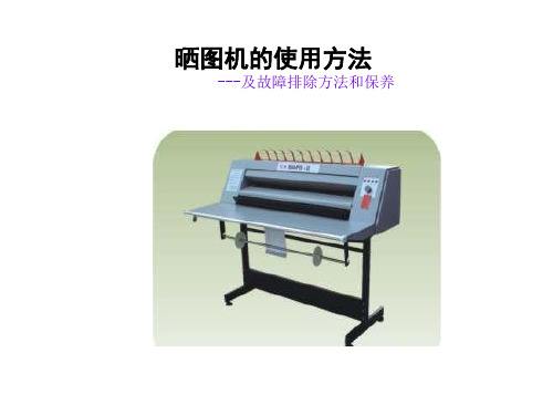
晒图机的使用方法
---及故障排除方法和保养
一、产品说明:
860PD产品特性 1.无氨,无须预热,适合小批量,经常晒图的单位使用。 2.压力式刮板显影,循环供液,可无限量一次晒图,涂布均匀, 分辨率高。
最好用有人操作着的照片
晒图纸入口
• 将硫酸纸拿走放好,然后, 把晒图纸平直的送进晒图纸 入口,最后,晒制好的图纸 就从上方的出纸口出来。
• 晒图纸和硫酸纸从出纸口出 来后,将硫酸纸拿走,只将 晒图纸放进入纸口
• 机器使用完毕, 将调速旋转 至0,稍等片刻,按下“电源” 按钮,机器停止运转,切断 电源。
硫酸纸和晒图纸进纸口
晒图机的保养
• 1:机器荧光灯,玻璃滚管应定期清洗保养。 • 2:显影液应定期更换,更换周期为一个月。 • 3、要经常清洁显影液糟保持干净。 • 谢谢O(∩_∩)O谢谢
3.方便的无级调速旋钮,根据原稿的深浅和晒图纸的感光速度调
节旋钮,晒出的图纸线性好,分辨率高。 4.操作方便,荧光灯棒,使用寿命长,可靠性好。
5.机器造型新颖美观,220V电源可适宜放置任何办公环境及个体
使用。 6.机器上方的出纸架,可以前后出纸,用户可以自由选择。
二、晒图机的注意事项:
• 开机前务必先检查是否需 要添加显影液,如需添加, 不能超过刻度线。添加之 后才可开启机器。 • 在机器运行中如果需要添 加显影液,必须停止机器 再添加或可以少添加。 • 再观察一下三支荧光灯棒 是否亮着。
最好用有人操作着的照片
进纸口
• 晒图前应将机器启动片刻,使 显影液能够循环回流。
晒图机知识

国内晒图机品牌大全及以品质分析来划分:
一线品牌:海军上将、海上旗舰,主要为中高档氨熏及水溶性无氨晒图机
二线品牌:万奥(中高档氨熏及水溶性晒图机)
三线品牌:中美合资休斯敦(中低档油性无氨晒图机),延中(中低档氨熏及油性无氨晒图机),飞星(中低档氨熏晒图机),和平(中低档氨熏及油性无氨晒图机)
1ห้องสมุดไป่ตู้晒图机分类及性能使用分析:
晒图机以显影方式的不同分氨熏晒图机及无氨晒图机二大类。
高档氨熏晒图机以线条清晰、存档期长受用户欢迎,缺点是有氨水味,耗电量大,需要预热和散热,且因国内大多数品牌晒图机密封性能差,除氨不彻底,氨水耗损大而受制约。
无氨晒图机又分二小类:油性无氨显影晒图机及水溶性无氨显影晒图机。油性无氨晒图机相对来说机型小巧,设计简单,不需预热,开机即用,耗电量小,无味道受要求不高的小型客户欢迎,缺点是晒图清晰度差,晒出的图纸潮湿,存档期短(一年左右,且自晒制图之日线条起越变越淡,直至消失看不到线条,如在市外施工使用的话期限更短)不适合长时间工作和批量作业,显影不匀且容易漏显影液;水溶性无氨晒图机都属中高档晒图机类别,显影效果清晰,无味,存档期长,缺点是结构复杂,耗电量大,需要预热和散热 ,维护费用高,购入成本高。
2.国内外晒图机品牌大全及性能分析:
国外晒图机品牌主要有荷兰奥西、意大利海军上将、日本理光、德国迈特、ARS、韩国龟映,美国蓝图、除韩国龟映、美国蓝图属于二线品牌外,理光、奥西、迈特都以质量性能稳定,晒图效果好,晒图负荷量大为国内大型设计院及知名企业广泛使用,并具极高声誉。但因购买需求量小,使用周期长,进口海军上将、奥西、迈特、龟映、理光都已停产,仅海军上将在天津纯国产化生产,剩下的进口原装的晒图机品牌中听闻日本理光还有一点存货。