电站电缆技术要求-1
电力生产防止电力电缆损坏事故的重点要求-V1
电力生产防止电力电缆损坏事故的重点要求-
V1
电力生产是现代社会经济发展与人民生活的重要保障。
然而,电力电缆损坏事故时常发生,对电网安全和稳定运行产生了严重的影响。
因此,防止电力电缆损坏事故是电力生产和管理的重点工作之一。
以下是电力生产防止电力电缆损坏事故的重点要求:
一、电缆的安装应严格按照设计方案、规范、标准进行,特别是在易受到外力冲击和挤压的地方。
二、电力电缆的质量应符合国家相关标准。
在使用前,应检查电缆的绝缘、屏蔽和金属护套情况,以确保电力电缆的安全运行。
三、在架空输电线路和敷设电缆时,应考虑周边环境的特点,避免路基沉降、洪涝灾害等自然因素对电缆造成损坏。
四、对于埋地电缆,在施工和检修工作前应做好详细的保存记录和定位标识,以便后期管理和维护。
五、电力电缆敷设时应注意保持一定的距离,以避免电缆之间相互干扰和受到热量的影响。
六、电力电缆的敷设和接头应更换或修补完整、准确缓和的记录。
请及时发现和处理故障,防止造成二次损害。
七、应加强员工的安全意识,确保员工在电力设备周围的安全操作,并规定有关防护措施。
八、对于末端用户的用电设备,除了要关注设备本身的情况外,还需要了解其电源电压、电流电压、电阻值等参数,并且每年进行一次检查和维修,避免电力安全隐患。
总的来说,防止电力电缆损坏事故需要全社会的重视和共同努力。
通过加强安全培训、拓宽技术路线、严格执行责任制,一定能够减少电力事故的发生,确保人民生活和国家经济的持续发展。
低压电缆标准 iec 60502-1

低压电缆标准iec 60502-1摘要:1.低压电缆的定义和分类2.IEC 60502-1 标准概述3.低压电缆的绝缘电阻标准4.低压电缆的判定标准及其应用正文:一、低压电缆的定义和分类低压电缆是指额定电压在0.6/1kv 以下的电缆,包含0.3/0.5kv、0.45/0.75kv 控制电缆以及0.6/1kv 低压电力电缆。
低压电缆以上还有3.6/6kv、8.7/10kv、8.7/15kv 和21/35kv 高压电力电缆,以及超高压100kv 的电缆。
低压电缆广泛应用于住宅、商业和工业等领域的电力传输和配电系统。
二、IEC 60502-1 标准概述IEC 60502-1 是国际电工委员会(IEC)颁布的一项关于低压电缆标准的国际标准。
该标准主要规定了低压电缆的额定电压、尺寸、绝缘材料、绝缘电阻、耐热性、防水性等技术要求和测试方法。
IEC 60502-1 标准对于保证低压电缆的安全性能和可靠性具有重要的指导意义。
三、低压电缆的绝缘电阻标准根据IEC 60502-1 标准,低压电缆的绝缘电阻应满足一定的数值要求。
在常温下(20 摄氏度),电缆芯线对地及各芯线之间的绝缘电阻应不小于以下数值:1.当电缆长度为500 米时,3kv 以下为200 兆欧;2.当电缆长度为500 米时,6kv-10kv 为400 兆欧;3.当电缆长度为500 米时,20kv-35kv 为600 兆欧。
当电缆长度大于500 米时,其绝缘电阻应按照实际长度以上述数值为基数进行换算。
此外,电缆头及铅包接地电阻不应大于10 欧姆。
四、低压电缆的判定标准及其应用低压电缆的判定标准主要依据其绝缘电阻值。
对于低压电气装置的交接试验,常温下电动机、配电设备和配电线路的绝缘电阻不应低于0.5m(对于运行中的设备和线路,绝缘电阻不应低于1m/kv)。
低压电器及其连接电缆和二次回路的绝缘电阻一般不应低于1m;在比较潮湿的环境不应低于0.5m;二次回路小母线的绝缘电阻不应低于10m。
配电网N-1供电安全准则
配电网N-1供电安全准则N-1安全准则:在正常运行方式下,电力系统中任一元件无故障或因故障断开,电力系统能保持稳定运行和正常供电,其他元件不过负荷,且系统电压和频率在允许的范围之内。
这种保持系统稳定和持续供电的能力和程度,称为“N-1”准则。
其中N指系统中相关的线路或元件数量。
近年来,随着电网的不断壮大,对电网稳定性及设备可靠性的要求越来越高,电网稳定导则和有关电网规划建设的技术导则对电网安全运行的N-1准则均提出了不同要求。
然而,由于规划、设计、运行及经营等不同部门、相关技术人员对这一准则的理解和认识不同,供电可靠性与电价未形成有效的利益互动关系,造成电网规划建设、生产运行中不可避免地产生先天性安全隐患,对电网的长远发展也造成了不利影响。
因此,有必要澄清对N-1准则的一些错误认识,提高电网投资效益和安全性、可靠性,在确保电网可持续发展的前提下,稳步提高供电可靠性。
1 N-1准则的本质按照电网稳定导则有关定义,N-1准则是指正常运行方式下电力系统中任意一元件(如线路、发电机、变压器等)无故障或因故障断开后,电力系统应能保持稳定运行和正常供电,其他元件不过负荷,电压和频率均在允许范围内。
N-1准则用于单一元件无故障断开条件下电力系统静态安全分析,或单一元件故障断开后的电力系统稳定性分析即动态安全分析。
当发电厂仅有一回送出线路时,送出线路故障可能导致失去一台以上发电机组,此种情况也按N-1原则考虑。
由此可见,N-1准则包含两层含义:一是保证电网的稳定;二是保证用户得到符合质量要求的连续供电。
从目前情况看,保证电网的稳定由于涉及整个电网安全,无论在资金投入、运行方式还是技术措施上均得到足够的重视,但在保证用户特别是边远地区用户连续供电方面仍存在认识上的不足,造成局部电网生产运行长期处于被动局面。
2N-1与系统稳定性要求电力系统稳定分为静态稳定、暂态稳定、动态稳定、电压稳定。
电力系统中单一元件无故障断开后,直接影响其静态稳定和电压稳定,使正常输变电能力受到限制,其中以发电机组和输电线路停运较为明显,尤其是单电源线路或单台主变压器供电的变电站,当线路或变压器停电检修时,影响最直接;电力系统中单一元件故障断开后,直接影响其暂态稳定、动态稳定和电压稳定,其中以发电机组故障、母线故障和输电线路故障较为突出,特别是枢纽变电站母线和网间联络线路。
电力电缆技术(1)

统包型电缆
l 在每相导电线芯上包缠称为相绝缘纸的 油浸纸绝缘带,在各相线芯绞合成缆的 同时,在各相线芯之间的空隙填以纸绳, 外面再包缠称为统包纸的油浸纸绝缘带,
l 在统包纸外挤压上铅包作防水密封 l 根据安装场地的需要在其外部再加上不
同的保护层 l 在15kV及以下电压等级 。
电力电缆技术(1)
分相铅包型纸绝缘电缆
用于6kV及以下电压等级,将被淘汰。 4.聚乙烯绝缘:熔融温度低(70℃),最高工作电压达500kV 5.交联聚乙烯:通过化学或物理方法将聚乙烯分子链间
相互交联。最高运行温度可达90℃,短路时导电线芯 允许的最高温度可达250℃。极大地提高了电缆的安 全载流量和短路容量。其最高工作电压达500kV。 从1 kV到220 kV的各种电力电缆中,交联聚乙烯是当前应 用最广的一种绝缘材料,几乎完全取代了纸绝缘。
l 介质损耗tgδ20 ℃ 0.0005
0.003
l 体积电阻 Ω.cm
1015
1013
l 最高运行温度 ℃ 90
65
l 允许高差
无
有
l 安装工艺
简单
复杂
l 制造工艺
简单
复杂
l 金属防水层中
低压无 全有
电力电缆技术(1)
电缆额定电压(UO/U)的选定
l 中性点的接地方式
l 1) 直接接地
l 2) 小电阻接地
电力电缆技术(1)
XLPE电缆例行试验项目
l 导体直流电阻测定 l 交流耐压试验 l 局部放电试验 l 外护层耐压试验(对护层绝缘有要
求的电缆)
电力电缆技术(1)
XLPE电缆交接试验项目
l 五阻值测量: (主绝缘电阻、外护套绝缘电阻、内衬层绝缘 电阻、铜屏蔽电阻和导体电阻)(后四项仅对 10kV~35kV 等级电缆)
电缆技术标准
电缆技术标准
电缆技术标准是指在电缆制造、安装和使用过程中所需遵循的技术规范和要求。
电缆作为输电、通信和控制系统中不可或缺的部分,其质量和性能直接影响着整个系统的稳定运行。
因此,制定和遵循电缆技术标准显得尤为重要。
首先,电缆技术标准应包括对原材料的要求。
电缆的导体、绝缘材料、护套材
料等都需要符合一定的标准,以确保电缆的导电性能、耐热性能、耐候性能等符合要求。
此外,对于电缆的结构和工艺也应有详细规定,包括导体的结构、绝缘层和护套的厚度、绝缘和护套的加工工艺等,这些都直接关系到电缆的使用寿命和安全性能。
其次,电缆技术标准还应包括对电缆的安装和使用的规范。
电缆的安装应符合
国家相关的建筑电气规范,包括敷设方式、敷设环境要求、敷设深度、敷设间距等。
在电缆使用过程中,还应有相关的监测和检测标准,以确保电缆在使用过程中的安全可靠。
另外,电缆技术标准还应包括对电缆的试验和检验的要求。
电缆在出厂前需要
经过一系列的试验和检验,包括导体电阻测试、绝缘电阻测试、耐电压测试、外观质量检验等,以确保电缆的质量符合标准要求。
在电缆使用过程中,还应有相应的定期检测和维护标准,以确保电缆的性能稳定和安全可靠。
总之,电缆技术标准对于保障电缆质量、确保电缆安全使用具有重要意义。
制
定和遵循电缆技术标准,不仅可以提高电缆的质量和性能,还可以保障电力、通信和控制系统的正常运行。
因此,各个相关行业的企业和机构都应高度重视电缆技术标准的制定和执行,以推动整个行业的健康发展。
电缆技术要求
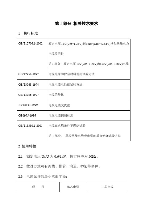
第1部分相关技术要求1 执行标准2 使用特性2.1 额定电压U0/U为0.6/1kV,额定频率为50Hz。
2.2 敷设方式可有沟槽、排管、沟道、桥架等多种。
2.3 电缆允许的最小弯曲半径:3 工作特性及条件3.1 电缆导体的长期允许工作温度为70℃。
3.2 短路时(最长持续时间不超过5s)电缆导体的最高温度不超过160℃。
4 技术要求4.1 导体4.1.1 导体结构、性能及外观符合GB/T3956-1997的规定。
4.1.2 导体表面光洁、无油污、无损伤绝缘的毛刺、锐边以及凸起或断裂的单线。
4.2 绝缘4.2.1 绝缘紧密挤包在导体上,且容易剥离而不损伤导体。
绝缘表面平整,色泽均匀。
绝缘层的横断面上无目力可见的气泡和砂眼等缺陷。
4.2.2 绝缘采用PVC/A型聚氯乙烯混和物,绝缘的平均厚度不小于GB/T12706.1-2002中规定的标称值,绝缘的最薄点厚度不小于标称值的90%-0.1mm。
4.2.3 绝缘线芯采用颜色识别,分色规则符合GB6995-1986的规定。
4.3 缆芯、填充及内衬层4.3.1 电缆绝缘线芯成缆方向为右向。
4.3.2 电缆的缆芯中用非吸湿性材料填充。
4.3.3 VV22型电缆成缆线芯外绕包两层PVC黑带作为内衬层,其厚度符合GB/T12706.1-2002的规定。
4.4 铠装4.4.1 单芯电缆采用双层不锈钢带铠装,多芯电缆铠装采用双层镀锌钢带铠装。
4.4.2 钢带螺旋式绕包,绕包间隔不超过钢带宽度的50%。
4.4.2 钢带厚度符合GB/T12706.1-2002的规定,钢带绕包圆整光滑。
4.5 外护套4.5.1 电缆外护套紧密挤包在铠装层上,护套表面光洁,色泽均匀。
4.5.2 电缆外护套材料采用PVC/ST1聚氯乙烯混和物;护套厚度符合GB/T12706.1-2002的规定,其任一点的最小厚度不小于标称厚度80%-0.2mm。
5 成品电缆5.1 成品电缆的机械物理性能等技术指标符合表1的规定。
电缆招标文件技术要求(一)2024
电缆招标文件技术要求(一)引言概述:电缆招标文件中的技术要求是指在招标过程中,对电缆产品的技术性能和质量要求进行明确和具体规定的内容。
技术要求的合理设置可以有效保证电缆产品在使用过程中的可靠性和安全性,同时也是电缆招标过程中评审供应商资格和选定最合适供应商的重要依据。
本文将从五个大点出发对电缆招标文件的技术要求进行详细阐述。
正文:一、电缆性能要求1. 电缆导体的导电性能要求2. 绝缘层的绝缘性能要求3. 外护层的耐磨性能要求4. 耐压性能和耐火性能要求5. 电缆的机械性能要求二、电缆尺寸要求1. 电缆截面面积和导体数量的要求2. 外径和壁厚的要求3. 弯曲半径和拖拉应力的要求4. 电缆长度和接头的要求5. 电缆重量和负载能力的要求三、电缆安装要求1. 电缆铺设方式和走线布局的要求2. 电缆接地和绝缘措施的要求3. 电缆附件和固定装置的要求4. 电缆引入和接头箱的要求5. 电缆标识和防护措施的要求四、电缆试验要求1. 传统试验和特殊试验的要求2. 电缆性能参数测量和测试方法的要求3. 电缆样品的选择和送检要求4. 试验报告的编制和审核要求5. 试验结果的评定和记录要求五、电缆质量控制要求1. 电缆材料和零部件的供应审核要求2. 电缆生产工艺和过程控制要求3. 电缆产品出厂检验和质量报告的要求4. 电缆追溯和控制文件的要求5. 电缆质量责任和售后服务的要求总结:电缆招标文件的技术要求是确保供应商提供合格电缆产品并满足工程建设和用户需求的重要保证。
通过对电缆性能、尺寸、安装、试验和质量控制五个大点的详细阐述,可以有效指导和规范供应商在电缆招标过程中的设计、生产和交付工作。
合理设置技术要求,不仅可以提高电缆产品的质量和可靠性,还可以提高供应商的竞争力和用户满意度。
电缆技术要求精编
电缆技术要求精编电缆是现代电力传输和通信领域中必不可少的设备,对电缆技术要求精编,以保证其安全可靠的运行。
以下是电缆技术的一些主要要求。
首先,电缆的导电材料应具有良好的电导性能和导电稳定性。
电缆的导电材料通常采用铜或铝等金属材料,这些材料具有良好的导电性能和机械强度。
在制造过程中,需要进行严格的电导率测试和导电稳定性测试,以确保导电材料的质量。
其次,电缆的绝缘材料应具有良好的绝缘性能和耐热性能。
绝缘材料的选择对电缆的绝缘性能有着至关重要的影响。
常见的电缆绝缘材料有聚乙烯、交联聚乙烯、聚氯乙烯等。
这些材料在制造过程中需要进行绝缘性能测试和耐热性能测试,以确保绝缘材料的质量。
另外,电缆的屏蔽层应具有良好的屏蔽性能和导电性能。
屏蔽层主要用于防止电磁干扰的影响,保证电缆信号的传输质量。
常见的屏蔽层材料有铝箔、铜箔等金属材料。
在制造过程中,需要进行屏蔽性能测试和导电性能测试,以确保屏蔽层的质量。
此外,电缆的外护层应具有良好的耐磨性和耐腐蚀性。
外护层主要用于保护电缆的内部结构不受外界因素的损害。
常见的外护层材料有聚氯乙烯、聚乙烯等。
在制造过程中,需要进行耐磨性测试和耐腐蚀性测试,以确保外护层的质量。
最后,电缆的安装和维护要求也是电缆技术要求的重要组成部分。
电缆的安装和维护应按照相关标准和规范进行,以确保电缆的正常运行和使用寿命。
在安装过程中,要注意电缆的弯曲半径、接头的可靠性等问题;在维护过程中,要定期进行电缆的巡检和维护,及时发现和处理故障。
综上所述,电缆技术要求精编,需要对导电材料、绝缘材料、屏蔽层材料、外护层材料等进行严格的质量控制和测试,同时要按照相关标准和规范进行安装和维护。
只有这样,才能确保电缆的安全可靠运行,满足电力传输和通信的需求。
- 1、下载文档前请自行甄别文档内容的完整性,平台不提供额外的编辑、内容补充、找答案等附加服务。
- 2、"仅部分预览"的文档,不可在线预览部分如存在完整性等问题,可反馈申请退款(可完整预览的文档不适用该条件!)。
- 3、如文档侵犯您的权益,请联系客服反馈,我们会尽快为您处理(人工客服工作时间:9:00-18:30)。
Ref. No. 300985Date December, 2009STANDARD SPECIFICATION E – 210CABLES AND WIRESSTANDARD SPECIFICATIONSE-210 CABLES AND WIRESTABLE OF CONTENTS1SCOPE OF WORK (1)2CODES AND STANDARDS (1)3DESIGN AND OPERATING CONDITIONS (1)3.1GENERAL (1)3.2CABLE SIZING CRITERIA (2)3.2.1Voltage Drop (2)3.2.2Cable Ratings (2)3.2.3Short Circuit Current Capacity (3)4DETAILED REQUIREMENTS (3)4.1GENERAL (3)4.2CABLE CONSTRUCTION (3)4.2.1Conductors (core) (3)4.2.2Insulation (4)4.2.3Conductor Jacket (4)4.2.4Bedding (inner covering and fillers) (4)4.2.5Armour (4)4.2.6Lead Sheath (4)4.2.7Outer Jacket (5)4.2.8Cable Splice and Rework (5)4.3SPECIFIC REQUIREMENTS (5)4.3.1Power Cables (5)4.3.2Control Cables (6)4.3.3Instrumentation Cables (6)4.3.4Thermocouple Extension Cables (7)4.3.5Special Application Cables (7)4.4CABLE INSTALLATION (7)4.4.1General (7)4.4.2Cable Splices (8)4.4.3Draw Pits and Joint Pits (8)4.4.4Preparation of Cable Trays and Trenches (9)4.4.5Preparation of Conduits and Ducts (9)4.4.6Cable Pulling Equipment (9)4.4.7Cable Pulling and Installation (10)4.4.8Pulling Tensions (12)4.4.9Protecting and Supporting Cables (13)4.4.10Cable Trenches and Cable Ducts (14)4.5CABLE FIRE BARRIERS (14)5TESTING AND FUNCTIONAL GUARANTEES (14)5.1CABLE TESTS AND TEST REPORTS (14)5.2MANUFACTURING TESTS (15)5.2.1Routine Tests (15)5.2.2Type Tests (15)5.3TEST AFTER INSTALLATION (15)5.4GUARANTEE (15)6CABLE NUMBERING SYSTEM (15)7QUALITY ASSURANCE/QUALITY CONTROL (QA/QC) (17)1SCOPE OF WORKThe work shall include the design, supply, manufacturing, factory testing, delivery to site, in-stallation, commissioning and testing of all cable and wires for power, control and instrumen-tation cables for this Project.The Bidder shall give clear and comprehensive information concerning the power, control andinstrumentation cable types that are to be provided, by completing Technical Schedule TS E-210, together with manufacturer's catalogues and technical information publications etc.2CODES AND STANDARDSThe Contractor shall comply with the requirements of Volume II, Part I, Section 2, Clause 2.5"Codes and Standards" and the following specific standards.IEC 60227 Polyvinyl chloride insulated cables of rated voltages up to and including450/750 VIEC 60228 Conductors of insulated cables.IEC 60230 Impulse tests on cables and their accessories.IEC 60245 Rubber-insulated cables of rated voltage up to and including 450/750 V.IEC 60287 Calculation of the continuous current rating of cables (100 % load factor).IEC 60332 Tests on electric cables under fire conditions.IEC 60502 Extruded solid dielectric insulated power cables for rated voltages from1 kV up to 30 kVIEC 60584-3 Thermocouples - Extension and compensating cable. Tolerances and identi-fication system.IEC 60811 Common test methods for insulating and sheathing materials of electric ca-blesIEC 60885 Electrical test methods for electric cables3DESIGN AND OPERATING CONDITIONS3.1GENERALPower, control, instrumentation, communication, thermocouple extension and special applica-tion cables shall have a minimum design life of 30 yrs when used under the following operat-ing and design conditions.Operating Voltages:System operating voltage levels are in accordance with Standard Specification E-001.Operating Temperatures:The maximum operating temperature of XLPE insulated conductors shall be 90 ºC.An emergency overload temperature of 130 ºC and a maximum short circuit tempera-ture of 250 ºC will be permitted for duration and frequencies as specified in the refe-renced IEC standards.Load Factor:The maximum load factor shall be 100 %.Installation:The cables shall be suitable for indoor and outdoor installations exposed in air, in con-duits, in cable trays, in underground concrete encased steel or plastic conduits, in un-derground trenches and for direct burial. Un-armoured cables shall be suitable for in-stallation in steel conduits.Environmental Conditions:The meteorological, seismic and environmental conditions for the Site are as indicatedin Volume II, Part I, Section 1, Clauses 1.3 “Site Conditions”.For cables installed in air the maximum continuous ambient temperature shall be assumed tobe 50 ºC.3.2CABLE SIZING CRITERIAThe Contractor shall use the following criteria for selecting and sizing the cables:3.2.1Voltage DropThe total voltage drop between main bus and the final equipment terminals in feeder andbranch circuits shall not exceed 5 % of bus nominal voltage. Individual branch circuit voltagedrop shall be a maximum of 3 % during normal operation and 10 % during motor starting.The voltage drop calculation for equipment shall be based on the rated nominal voltage of thedistribution bus feeding the equipment, full load current of the equipment being fed at its ratedvoltage and maximum feeder cable impedance.The voltage drop in control circuit wiring shall not exceed a value that may cause contractorsto drop out, or cause auxiliary relays or contractors to fail to pick up or the control system tomalfunction in other way under any auxiliary system voltage condition, including during thestarting of large motors. In critical cases, voltage drop calculations shall be done for controlcircuits and larger size conductors shall be used as necessary to ensure proper operation of thecontrol system.3.2.2Cable RatingsThe nominal cable ratings shall be rated based on the method of installation and groupings inaccordance with the cited standards as follows:•Cables ratings in concrete duct banks shall be calculated in accordance with IEC 60287, based on a soil thermal resistivity of not less than 1.2 K.m/W(Kelvin-metre/Watt) and a soil temperature of not less than 30 o C.•Cables in cable trays shall be sized in accordance with IEC 60287 applying appropriate derating factors according to a recognised standard which take ac-count of the ambient conditions and installation conditions. The depth of fillshall not exceed 50 mm for power cables. Sufficient design margin shall beprovided in sizing the cable trays so that 10 % more cables can be added by theOwner in the future. The effect of covers and solar radiation on outdoor cabletrays shall be taken into account in sizing calculations.•Cables in conduits shall be sized in accordance with IEC 60287.Other de-rating factors, which shall be considered, are as follows:a. The ambient temperature at the termination point shall be considered to be 50 ºC.b. 10 % de-rating factor due to current unbalance when two or more conductors per phaseare used.c. The Contractor's cable rating calculations shall be submitted to the Owner for review.All cables shall have adequate conductor sizes to carry the full starting current of the motors,during the period of motor acceleration without exceeding the specified short duration con-ductor temperature of 130 ºC.3.2.3Short Circuit Current CapacityThe cable designs shall be fully co-ordinated so that they are fully capable of sustaining theSpecified ground fault currents without damage to the metallic screen, metallic sheath or ar-mouring etc.The short-circuit capability shall be based on using the total operating time for protective re-lays and breaker fault clearing time or on the fuse let-through current and energy.Under worst conditions, the conductor temperature shall not exceed its maximum short circuittemperature of 250 ºC.The Contractor's calculations for cable short circuit current capacity shall be submitted to theOwner for review and approval.4DETAILED REQUIREMENTS4.1GENERALInterconnecting wiring to control components such as flow, pressure and limit switches, tem-perature devices, solenoids, 230 V a.c. motor drives, etc., local control cabinets or junctionboxes shall be wired in strict accordance with Contractor's Drawings. Refer to Volume II, PartI, Section 2, Clause 2.2 "Data and Drawing Submission".All terminals and wires shall have identifications as shown on Contractor's schematic and wir-ing diagrams. All wiring shall be installed exactly as shown on the "for construction" wiringdiagrams.Wiring between equipment, or equipment and terminal blocks mounted on the same skid orshipping section shall be continuous with no splices.Single conductor control cables shall not be run in cable trays.Cables outside of an enclosure or junction box shall be protected by conduit or shall be ar-moured. If armour is used without conduit it shall meet the requirements of Clause 4.2.5.4.2CABLE CONSTRUCTIONThe cables shall be single conductor or multi-conductor assemblies, as specified.4.2.1Conductors (core)All conductors, except thermocouple extension cables, shall be Class 2, annealed strandedcopper in accordance with IEC 60228.Thermocouple extension cable conductors shall be solid and conductor materials shall be perIEC-60584-3.Conductors shall be coated or other means shall be provided to ensure clean stripping of insu-lation and/or conductor shield.The medium-voltage power cable conductors shall be provide with a layer of extruded semi-conducting compound with an average thickness of 0.38 mm and minimum thickness of notless than 0.30 mm.4.2.2InsulationThe insulation shall be a high quality, non-flame propagating, ozone resistant extruded soliddielectric of either ethylene propylene rubber (EPR) or cross-linked polyethylene (XLPE) forPower Cable and PVC (coaxial or not) for instrument control and communication.For high temperature (125-150 ºC) applications silicone rubber or Tefzel insulation shall beused as reviewed by the Owner.The average insulation thickness for power cables shall not be less than the nominal valuesspecified in Tables III and IV of IEC 60502. The thickness of any separator or screen on theconductor or over the insulation shall not be included in the thickness of the insulation.4.2.3Conductor JacketAll power cables shall be provided with a fire retardant and low acid and gas evolution jacketover the individual conductors. This jacket shall be of heavy duty chlorosulfonated polyethyl-ene (Hypalon) or polychloroprene (Neoprene) or PVC.The details of the fire retardancy and related tests shall be submitted with the Tender Proposal.4.2.4Bedding (inner covering and fillers)Multi-conductor cables shall have bedding, which shall be suitable for the specified operatingtemperature and insulating material. The bedding material shall be termite resistant.All cables shall be provided with water-blocking material.4.2.5ArmourAll multi-conductor cables shall be provided with continuous, close fitting, galvanised steelwire armour unless otherwise indicated or accepted in writing by the Owner. The armourgrounding shall be in accordance with Standard Specification E-217 "Building and EquipmentGrounding and Lightning Protection".Single conductor power cables shall be armoured with non-magnetic corrosion resisting ar-mour. The maximum armour voltage to ground shall not exceed 25 V.The armour shall be impervious to attack by termites, rats and other vermin.4.2.6Lead SheathCables subject to permanent or prolonged contact with water shall be provided with a leadsheath.4.2.7Outer JacketAll cables shall be provided with a fire retardant and low acid gas evolution outer jacket overthe armour. This jacket shall be of heavy-duty chlorosulfonated polythylene (Hypalon) orpolychloprene (Neoprene). Polyvinyl chloride (PVC) outer jackets may be used for cables inoutside trenches or ducts provided they do not enter a building or similar enclosure.The details of fire retardancy and related tests shall be submitted with Tender Proposal.All cables shall be permanently identified by permanent surface printing or indenting (not toexceed 15 % of the outer jacket thickness) to show the following:•Manufacturer’s Name•Rated Circuit Voltage•Conductor Size•Number of Conductors•Insulation Material (not trade name)•Jacket Material (not trade name)•Year of ManufactureThe distance between the end of one complete set of marks and the beginning of the next shallnot exceed 500 mm. All marking shall be legible and shall be made with colours in contrastwith the outer jacket colour.4.2.8Cable Splice and ReworkFactory cable splices and/or rework of the insulation and jacket is prohibited unless agreed toby the Owner in writing, in which case the following shall apply:a. Splices and/or rework of the insulation and jacket may be required during manufacturingto eliminate defects, obtain specified shipping lengths, etc. Any such rework of splicesshall conform to the material, dimensional and test requirements of the cable.Conductors and cables, which have been reworked or spliced, shall be tested as requiredfor the specified cable and manufacturer shall include with his test reports the results ofany tests for such rework and splices. Factory splices shall be made so that individualstrands of the conductor are butt-brazed and the brazes are staggered at intervals of atleast 5 mm.b. Materials for splices and rework shall be controlled and documented in accordance withthe quality assurance/ quality control requirements as referenced in Clause 6.Field cable splicing and/or rework is prohibited in all but exceptional cases4.3SPECIFIC REQUIREMENTS4.3.1Power CablesMedium-voltage cable:•10 kV rated 8.7/15 kV (highest system voltage 12 kV)Earthing conditions are in accordance with Category A of IEC 60502.Low-voltage power cables may be single, two, three or four conductor cable with a voltage rating of 0.6/1 kV.The minimum conductor size for power cables shall be 2.5 mm².All power cable conductors shall be identified by colouring the individual conductor jackets as follows:Number of Conductor PhaseLetterDesignationColourThree 1, 2, 3 L1, L2, L3 Red, Yellow, Blue- Neutral N Black- Protective Earth PE Green-Yellow DC - cables- Positive L+ Grey- Negative L- Blue The outer jacket shall be coloured black for medium-voltage cables and black for low-voltagecables.4.3.2Control CablesControl cables shall be rated 600 V.The minimum conductor size for control cables shall be 1.5 mm².The minimum conductor size for current transformer secondary circuits shall be 2.5 mm².Each conductor shall be identified by numbering and/or colour codes.The insulation of all individual conductors shall be the same colour (black, white or natural),with surface printing of numbers in sequence.The outer jacket shall be coloured black.4.3.3Instrumentation CablesInstrumentation cables shall be rated 600 V. Instrumentation cables shall be shielded twistedpairs.The minimum conductor size shall be 0.5 mm². Conductors shall be chosen as stranded type,suitable for connection via Maxi-Termi-Point technique.Each pair shall be twisted with a lay of approximately 50 mm.The cable shall be composed of conductor bundles, each bundle comprising 4 pairs (excep-tion: 2-pair cable shall have two bundles). The 4 pairs of each bundle shall be twisted (1twist/m) and the bundles shall be twisted to form the cable (1 twist/m).Each multiple pair cable shall be provided with an overall shield of copper or plastic coatedaluminium foil and one drain wire.The minimum drain wire conductor size shall be 0.5 mm² for all instrument cables. The drainwire shall be in intimate contact with the metal part of its shield.The conductor-ident-code shall be as follows:Pair-No. Conductor A Conductor B1 blue red2 grey yellow3 green brown4 white blackIdentification of different bundles shall be made by numbered plastic foilFor instrumentation cables the outer jacket shall be coloured grey.4.3.4Thermocouple Extension CablesThe cables shall be rated for 600 V and shall consist of single or multiple twisted pairs withindividual drain wires and shields (plastic coated aluminium foil or copper). The cables shallalso have an overall shield, drain wire and jacket and be of similar construction to instrumentcables, Clause 4.3.3.Multiple-pair thermocouple extension cables may use a minimum conductor size of 0.75 mm².The thermocouple extension cable conductor materials shall be thermocouple materials as re-quired for the application chromel-constantan, chromel-alumel, etc.The colours shall be in accordance with IEC-60584-3 and as follows:Cable TypeColour of InsulationPositive - Negative Colour of Overall JacketChromel-Alumel Yellow – Red YellowChromel-Constantan Purple – Red PurpleMultipair cables shall consist of pairs of conductors with colours as indicated above. The pairsshall be identified by surface printing of numbers in sequence on each conductor of each pair(same number on each conductor of a given pair).4.3.5Special Application CablesThe Contractor shall provide all special application cables required for various equipmentprovided as part of the Work.In general, the cables shall meet the requirements specified herein for a 30 yrs design life ofthe Power Plant.The Contractor's recommendations on the type and construction of the cable for these applica-tions shall be given due consideration.4.4CABLE INSTALLATION4.4.1General。