johnson-cook模型原始论文-1983-johnson-cook
Johnson-Cook 材料模型及失效模型

;1.0E+06 3.0E+09 4.1+09 8.2E+09 4.3E+10 1.0
$ D1 D2 K1 K2 K3 FS 1 L7 b3 X/ ^6 z2 c# w" ?$ S
;0.01 1.0 1.6E+11 2.6E+11 3.6E+11 -0.1 % l) V& @; J/ g* d9 t
[2] G. Kay. Failure modeling of titanium 6Al-4V and aluminum 2024-T3 with the Johnson-Cook material model. Tech. Rep. DOT/FAA/AR-03/57. US department of Transportation, Federal Aviation Administration, September, 2003.
D = Σ (Δε/εf) (4)
式中
εf = [D1 + D2exp(D3σ*)][1+D4lnε*][1+D5T*] (5)
Δε - increment of effective plastic strain during an increment in loading
σ* - mean stress normalized by the effective stress
D1, D2, D3, D4, D5 - constants
当D = 1时发生失效。失效应变εf和损伤的累积,是平均应力、应变率和温度的函数。
材料 Ti-6Al-4V TitaMQUIST_CERAMICS
铝合金ansysjohnson-cook数值模拟参数
铝合金ansysjohnson-cook数值模拟参数
铝合金的Johnson-Cook本构模型是常用的金属材料本构模型之一,其参数包括材料的流变应力指数(n)、材料的强化指数(m)、材料的屈服应变(ε0)、材料的塑性应变速率敏感指数(C)、材料的弹性模量(E)以及材料的热膨胀系数(α)。
这些参数是通过实验测量或者模拟求解得出的,具体数值因材料而异,需根据实际情况进行确定。
常用的Johnson-Cook本构模型公式如下:
σ = σ0 +
Kε^n[1+(ε/ε0)^m][(1+ln(ε/ε0))/ln(ε̇/ε̇0)]^C 其中,σ为铝合金的应力,ε为应变,σ0为流变应力,K为强化系数,ε0为屈服应变,m为强化指数,n为流变应力指数,C为塑性应变速率敏感指数,ε̇0为参考应变速率,ln为自然对数。
激光冲击Johnson-Cook模型材料参数优化
2 1 年 4月 02
兰
州
理
工
大
学
学
报
VD 8 L3 No 2 . Ap . 0 2 r2 1
J u n l fL n h uUnv riyo c n lg o r a a z o iest fTeh oo y o
文章编号 : 635 9 (0 2 0 -0 50 1 7 -1 6 2 1 ) 20 1 -4
数优化方法简单易行. 关键词 : 激光冲击强化 ; 残余应力 ; o no - o k模 型;材料参数 ; 交率 Jh snC o 应
中 图分 类 号 :T 1 Gl3 文献 标 识 码 :A
J l o - o k mo e fma e il a a tro t z t n frlsrs ok r c si oms n C o d l tra r mee p i ai o e h c p o esn o p mi o a
m ae ilp r m ee ss o l eo t ie r e o o ti o ea c rt eu ta dt a sf rh rv r— t ra a a t r h u db p i z di o d rt b an m r c u aer s l n h twa u t e ei m n
光冲击强化残余应力场 的数值仿真. 通过仿 真分析及 试验结果 对照 , 明以 Jh s nC o 说 o no - ok模型作 为本 构关 系是可 行的, 激光冲击能形成残余压 应力层, 提高疲劳寿命 , 由于 应变率 的差异 , 但 必须对 J C模 型材 料参数进行 优化 , 才
能取得较精确的结果 , 并从激光功率密度 对残余 应力场的分 析进 一步加 以验证. 结果表 明, 出的 J 提 C模型 材料参
Q235B钢Johnson_Cook模型参数的确定_林莉
变率的关系可写为 σ eq = A( 1 + C lnε ) 。 温度软化参数 m 可以通过研究在不同温度下的屈服应力获得; 同样 地, 应变率敏感参数 C 可以通过标定材料在不同应变 率下的屈服应力获得。 此外, 还应该考虑高应变率造成的温度升高。 假 设加载过程为绝热的, 材料温度的升高可以用塑性功 的消耗来表示, 即 ΔT = χ ρ 是材料密 其中, ∫ σ dε , ρC p eq eq
[3 ]
等
[9 ]
, Mackenzie 等[10], Johnson 等[11]。 塑 性 变 形 引 起
[9 , 11 ]
的延性断裂极大地依赖于应力三轴度
, 同时应变
率和温度也对材料的延性断裂有不可忽略的影响。 另 外, 最近 的 一 些 研 究 展 示 了 断 裂 应 变 可 能 也 依 赖 于 Lode 参数[12], 但其与断裂准则的关系还在进一步的研 J-C断 究之中。在涉及到材料动态断裂的计算领域, 裂准则
[11 ]
在数值仿真中通常用两类模 所述,
50978077 , 51078103 ) ; 黑 基金项目: 国家自然科学基金项目( 51378164 , 龙江省教育厅科学技术研究面上项目( 12531135 ) 收稿日期: 2013 - 02 - 17 修改稿收到日期: 2013 - 10 - 16 1973 年 1 月生 第一作者 林莉 女, 博士生,
* * 向压缩试验 σ = - 1 / 3 , 纯剪切试验 σ = 0 , 单向拉伸 * [17 ] 试验 σ = 1 / 3 。对缺口拉伸试验, 通过 Bridgman 的 * 初始应力三轴度可以通过下式计算: σ0 = 1 / 3 + 研究,
数。为了更精确地拟合实验数据, 对 J - C 强度和失效 模型进行了适当的修改。 最后通过 Taylor 试验验证了 所获取参数的有效性。
johnson—cook模型参数
《探寻Johnson-Cook模型参数的深度与广度》1. 引言在材料科学和工程领域中,Johnson-Cook模型是一种常用的材料本构模型,用于描述金属材料在高应变率和高温条件下的本构行为。
该模型的参数对于模拟和预测材料的力学性能至关重要。
本文将围绕Johnson-Cook模型参数展开讨论,深入探究其深度与广度。
2. Johnson-Cook模型简介Johnson-Cook模型是由Johnson和Cook在1983年提出,用于描述金属材料在动态加载和高温条件下的本构行为。
该模型基于实验数据,并考虑了材料的应变率、温度和应变硬化效应。
在Johnson-Cook模型中,参数包括A、B、n、C和m等,它们分别代表了材料的流动应力、应变硬化指数、热软化指数和材料的温度敏感性等重要性质。
3. 参数A的理解和研究3.1 参数A表示了材料的流动应力,在Johnson-Cook模型中具有重要的意义。
对于不同金属材料,参数A的取值不同,反映了材料的强度特征。
通过实验测试和数值模拟,研究人员可以获得不同条件下参数A的数值,从而深入理解材料的力学性能和变形行为。
3.2 个人观点:对于参数A的研究需要综合考虑材料的微观结构和宏观性能,通过建立参数A与其他参数的关联模型,可以更深入地理解材料的强度特征和动态响应。
4. 参数B、n的相关性研究4.1 参数B和n分别代表了材料的应变硬化指数和变形行为。
它们的取值对于描述材料的塑性变形过程至关重要,而且彼此之间存在一定的相关性。
通过实验测试和数值模拟,研究人员可以探究参数B、n 与材料微观结构和塑性变形特征之间的关联,以期深入地理解材料的本构行为。
4.2 个人观点:参数B和n的研究不仅需要考虑材料的单调拉伸试验数据,还需要结合压缩试验、扭转试验等多种试验数据,以全面、深入地评估材料的塑性变形特征和本构行为。
5. 参数C、m的温度敏感性研究5.1 参数C和m代表了材料的热软化指数和温度敏感性。
镍johnsoncook 参数

文章标题:探秘镍的Johnson-Cook参数1. 引言镍是一种常见的金属元素,具有良好的耐腐蚀性和热稳定性,因此在工业生产中得到广泛应用。
而Johnson-Cook参数是描述镍材料在高速、高温条件下的变形和破裂行为的重要参数。
本文将从镍材料的特性、Johnson-Cook参数的定义和作用、实验测定方法以及应用领域等方面进行探讨。
2. 镍的特性镍是一种银白色的金属元素,具有良好的延展性和导电性。
在高温环境下,镍仍能保持较高的稳定性,因此在石油化工、航空航天、汽车制造等领域得到广泛应用。
然而,镍材料在高速冲击和高温条件下的变形和破裂特性对材料的工程应用具有重要影响。
3. Johnson-Cook参数的定义和作用Johnson-Cook模型是一种常用的材料本构模型,用于描述金属材料在高速冲击条件下的变形和破裂行为。
该模型通过Johnson-Cook参数来描述材料的动态力学行为,包括应变硬化、温度效应和应变率效应等。
Johnson-Cook参数包括流变应力、硬化指数、材料常数和断裂应变等,它们对材料的动态变形和破裂性能起着重要作用。
4. 实验测定方法为了准确描述镍材料的Johnson-Cook参数,需要进行一系列的实验测定。
常用的实验包括高速冲击试验、高温拉伸试验和压缩试验等,以获取材料在不同条件下的应力应变曲线。
通过曲线拟合和参数识别的方法,可以得到镍材料的Johnson-Cook参数,从而为材料的工程应用提供重要参考。
5. 应用领域镍材料的Johnson-Cook参数对于飞行器、火箭发动机、汽车零部件等高速高温环境下的结构件设计和性能预测具有重要意义。
通过准确描述材料的动态变形和破裂特性,可以指导工程师设计更安全、可靠的材料结构,降低事故风险和维护成本,推动高温高速领域的科学研究和工程应用。
6. 个人观点和理解作为我作为你的文章写手,我对镍的Johnson-Cook参数有着浓厚的兴趣。
通过深入研究和撰写本文,我进一步了解了镍材料的特性和Johnson-Cook参数的重要性。
johnson-cook断裂准则及参数获取方法
johnson-cook断裂准则及参数获取方法全文共四篇示例,供读者参考第一篇示例:Johnson-Cook断裂准则及参数获取方法是一种用来描述材料在高应变速率下的变形行为和断裂过程的数学模型。
该准则在工程领域广泛应用于弹塑性材料的高速冲击和爆炸加载等工况下的数值模拟分析。
本文将详细介绍Johnson-Cook断裂准则的基本原理、模型表达式以及参数获取方法。
Johnson-Cook断裂准则基本原理\[\sigma =[A+B(\varepsilon_p)^n][1+C\ln(\dot{\varepsilon}_p)](1+D\ln\left (\frac{T-T_0}{T_m-T_0}\right))\]\sigma表示材料的等效应力,\varepsilon_p表示有效应变,\dot{\varepsilon}_p表示有效应变速率,T表示温度,T_0表示材料的参考温度,T_m表示材料的熔点,A、B、n、C和D为Johnson-Cook模型的参数。
Johnson-Cook断裂准则的参数获取是构建数学模型的关键步骤,在实际工程应用中,一般通过试验数据拟合的方法获取参数。
常用的获取方法包括材料拉伸试验、冲击试验、压缩试验等。
下面将介绍几种常用的参数获取方法:1. 材料拉伸试验:将材料制备成标准试样,在材料拉伸试验机上进行拉伸试验,得到应力-应变曲线。
通过拟合实验数据,可获取Johnson-Cook模型的参数A、B和n。
2. 冲击试验:冲击试验是一种用高速冲击加载材料获取其变形和断裂性能的试验方法。
通过对不同应变速率下的材料进行冲击试验,可以获取Johnson-Cook模型的参数C。
在实际工程应用中,有时候通过单一试验无法获取所有的参数,需要结合多种试验数据进行参数拟合。
还可以通过有限元数值模拟方法,利用试验数据进行参数优化拟合,以获得更精确的Johnson-Cook断裂准则参数。
第二篇示例:Johnson-Cook断裂准则是一种用于描述材料在高应变速率下破坏行为的经验模型。
johnson-cook力学本构模型
johnson-cook力学本构模型约翰逊-库克力学本构模型是一种描述固体材料的非线性变形和失效行为的力学模型,广泛应用于机械工程、材料科学、爆炸动力学等领域。
约翰逊-库克力学本构模型是由美国犹他大学的两位研究人员约翰逊和库克于1983年提出的。
它是一种经验性本构模型,适用于金属等大变形材料的失效特点研究。
该模型的优点是描述了材料的很多失效行为,如塑性、蠕变、断裂等。
缺点是需要较多的材料实验数据,且选取参数较困难。
该本构模型的核心在于使用一个修正的强度函数,该函数可以反映材料的动态增强和动态软化特性。
其中,强度函数表示为:σ=ε[(A+Bεp)(1-Clnεp)+Dln(εp/εp0)](1+ε˙/ε˙0)^n其中,σ为应力,ε为应变,εp为塑性应变,A、B、C、D、n、ε˙0、εp0均为本构模型参数。
该强度函数的特点如下:1.描述了动态增强和动态软化特性。
随着应变率的增加,材料的强度增加,但塑性应变也随之增加,达到一定程度后,材料变脆并出现软化。
2.考虑了材料的压缩和拉伸特性。
A和B参数控制材料在拉伸和压缩下的应力响应。
3.考虑了材料的应变率效应。
n参数表示应变率对材料强度的影响程度。
在该本构模型中,还引入了力学损伤参数D和反应率参数C。
D表示材料的累积剪切变形量对材料强度降低的影响,C则描述了材料在应变程度超过某一界限时出现的软化过程。
该本构模型的参数选择需要依据材料实验数据,通过拟合实验结果来确定,要求较高的实验技术和分析能力。
同时,该本构模型适用于大变形材料的研究,对于其他类型材料的研究需要进一步改进和完善。
- 1、下载文档前请自行甄别文档内容的完整性,平台不提供额外的编辑、内容补充、找答案等附加服务。
- 2、"仅部分预览"的文档,不可在线预览部分如存在完整性等问题,可反馈申请退款(可完整预览的文档不适用该条件!)。
- 3、如文档侵犯您的权益,请联系客服反馈,我们会尽快为您处理(人工客服工作时间:9:00-18:30)。
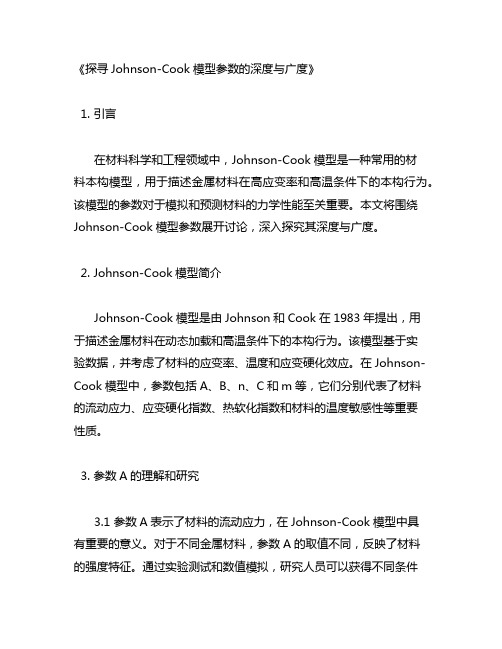
HARDNESS GRAIN ELASTIC SIZE
___~
o.D%-0.150 d
PROPERTIES E (GPaJ 0.34 IGPal (GPa) I 207 0.29 200 0.29
ELASTIC MODULUS, POISSON’S
RATIO, Y E/2(1 + VI E/3(1 -2 Y i _”
Air Force Armament
Ahstrac-This paper considers fracture characteristics of OFHC copper, Armco iron and 4340 steel. The materials are subjected to torsion tests over a range of strain rates, Hopkinson bar tests over a range of temperatures, and quasi-static tensile tests with various notch geometries. A cumulative-damage fracture model is introduced which expresses the strain to fracture as a function of the strain rate, temperature and pressure. The model is evaluated by comparing computed results with cylinder impact tests and biaxial (torsion-tension) tests.
31
32
G. R. JOHNSON Table I. Physical properties of OFHC
and W. H. COOK
copper,
Armco
iron and 4340 steel
HEAT TREATMENT TEMPERATURE -__ TIME AT TEMPERATURE tK) (MINUTES) e~OCKWELL~ (mm1 F-30 0.060-0.090 j -__ F-72 j c -30 < 0.010
HEAT, cp k/pi+, COEF.
MELTING TEMPERATURE,
cannot be accurately evaluated after necking occurs in the tensile specimen. While these data can be helpful in examining strength characteristics, fracture characteristics can be determined only by examining post-tested specimens as shown in Fig. 4. The photographs of Fig. 4 and the metallographic sections of Fig. 5 both show the relatively ductile fracture of the OFHC copper and Armco iron, when compared to the 4340 steel. In Fig. 5, voids are most evident in the Armco iron and some are present in the OFHC copper. The 4340 steel also shows some void formation at elevated temperatures. Quasi-static tensile data are shown in Fig. 6. The notched geometry specimens are identical to those used elsewhere and give a concentration of hydrostatic tension in the test specimen [6]. This is clearly shown in the data of Fig. 6. For a specified true strain, the stress (including hydrostatic tension) increases as the notch becomes more severe. It can also be seen that the presence of the hydrostatic tension significantly decreases the strain at which the material fractures. Figure 7 shows metallographic sections of the quasi-static tensile test specimens. The OFHC copper and Armco iron fail in a more ductile manner than the 4340 steel, as expected. The formation of voids is apparent in the unnotched OFHC specimen and all of the Armco iron specimens. No voids are evident in the 4340 steel specimens.
INTRODUCTION WHENMATERIALS are subjected to dynamic loading conditions such as high velocity impact, explosive detonation or metal forming operations, a wide range of strains, strain rates, temperatures and pressures may be experienced. In some instances there has been a tendency to distinguish “dynamic” material properties from “static” material properties. The underlying assumption is that the differences between the “dynamic” and “static” properties must be due to strain rate effects only. Often associated with high strain rates, however, are large strains, high temperatures and high pressures. Therefore, it is important that the effects of each variable be properly assessed, rather than assuming all distinguishing characteristics are due to strain rate alone. This paper considers fracture characteristics of OFHC copper, Armco iron and 4340 steel. A series of laboratory tests has been performed to determine the effects of strain rate, temperature and pressure on the strain to fracture. A cumulative-damage fracture model is developed and evaluated with an independent series of tests and computations. TEST DATA A description of the three materials is given in Table 1. All of the test specimens were fabricated from the same material stock and the heat treatment was always as specified in Table 1. The torsion test data are shown in Fig. 1. The torsion tester is described in Ref. [I] and the procedure for analyzing the data is given in Ref. [2]. Data for a wide range of other materials are presented in Refq. [3] and [4]. For the data in Fig. 1 the average shear strain, 7, is assumed to occur only in the thin test section, and to occur uniformly along that section. At the higher strain rates, however, there may be some localizations of strain due to adiabatic heating[2]. The average shear strains at fracture are clearly shown for the Armco iron and the 4340 steel. None of the OFHC copper specimens in Fig. 1 fractured due to rotational limitations of the torsion tester. Another shorter-gage, OFHC copper specimen was tested at 3 = 0.008 s-’ and it fractured at 7 = 8.7. Metallographic sections of three torsion specimens are shown in Fig. 2. The OFHC copper specimen appears to exhibit a strain localization near the center of the gage section. There are no voids evident in any of the sections. The tensile Hopkinson bar data are shown in Fig. 3. A representative Hopkinson bar apparatus and data for various materials are presented in [5]. The specific Hopkinson bar used for the data of Fig. 3 is located at the Air Force Armament Laboratory (AFATL) at Eglin Air Force Base. The elevated temperatures were obtained by surrounding the in-place test specimen by an oven such that the temperatures were applied for several minutes prior to testing. The true tensile strain in Fig. 3 is based on the assumption that there is uniform axial strain in the tensile specimen. The stress-strain data are shown only for relatively small strains because they