转动极板控制器使用手册_V1.3
单杆 单位位置或三路(多位置)旋转调节器120VAC, 60Hz说明书

fuse. Installation is complete.
Connect wires per WIRING DIAGRAM as follows: Screw wire nuts on clockwise making sure no bare conductors show below the wire connectors. Secure each connector with electrical tape. NOTE: Control can be installed on either the Load or Line side. • Green dimmer Ground lead to Green or bare copper
wires.
• Remaining Red dimmer lead to remaining wall box wire.
• Proceed to Step 6.
Step 5b 3-Way Wiring Application:
Black Red Green Red
Neutral Ground
Insert wires straight then
twist clockwise
Electrical Tape
Step 7 Dimmer Mounting:
leads.
• Make sure that the ends of the wires from
the wall box are straight (cut if
necessary).
• Remove 5/8" (1.6 cm) of insulation from
Eaton XT电机控制器系列产品说明说明书

Win-win with push-in: XT motor controlEaton’s XT motor control now offers push-in technology. This new tool-free connection technology makes wiring even faster, safer, more efficient and reliable. The XT motor control solution with push-in technology offers maximum reliability, can be used anywhere in the world, and integrates seamlessly into existing control panel designs.No screws needed—just one clickThe push-in terminals enable safe and easycontrol-panel wiring with just one click with ferrule. Or if you’re not using ferrule wires, it’s still quick and easy to connect without using the screw. With our modular system and wide range of accessories, you’ll always find the right solution for your application.Because of their compact, space-saving size, these devices can be easily integrated into existing control cabinet designs.XT motor control, the win-win effectFaster, more cost-effective and reliable at the same timeFuture-proof your control panel the simple way Technicians and purchasers alike benefit from Eaton’s push-in range of devices. Eaton’s tried and tested XT motor control and state-of-the-art push-in technology makes wiring more efficient and reliable. Y ou too can benefit from this win-win effect by future-proofing your control panel the simple way.C frame contactors B frame manual motor protectorsB frame contactor andcontactor relays2EATON XT contactors and manual motor protectors with push-in technologyXT motor control overview3EATON XT contactors and manual motor protectors with push-in technologySystem expansion with push-in technologySimplify and optimize the installation and design of your machines and systems by using Eaton’s tool-free push-in technology, which is suitable for use without restrictions anywhere in the world.With the simplified wiring process, establishing the connection is up to 50% faster (compared to screw terminals), thereby increasing the competitiveness of your products.ote: N Secure connections can still be made without a ferrule by simply using a screwdriver to help the wire slide into place.XT contactorsThe XT contactors are powerful, efficient and versatile and can be combined with Eaton’s entire product range. The XT contactors are suitable for global use and cover the entire output range, from mini contactor relays (up to 7 A) to vacuum contactors (up to 3180 A).Eaton has extended the rated current of the contactors with push-in connection technology to 38 A (AC-3).Through the expansion of our product range and the use of the new push-in technology, we’ve made wiring even easier, faster, safer and more reliable.Protecting and switching IE3 motorsThe latest update of the Energy-related Products (ErP) Directiverequires increasingly energy-efficient electric motors, with important implications for their design and protection systems. Eaton’s contactors, motor-protective circuit breakers and motor-starter combinations meet the challenges associated with protecting and switching IE3 motors.More features, same frame widthThe base unit of the contactors with screw technology from our XT family previously contained either an NC or NO auxiliary contact. The contactors with push-in technology are now equipped with two auxiliary contacts (1NC contact and 1NO contact) as standard. Thefootprint, however, remains the same.Faster commissioning• Tool-free and simplified installation•Time savings of 50% compared to screw terminalsImproved machines and systems•High level of vibration and shock resistance, i.e., no need to retighten the cable connections after transport; immediately ready for use •Maintenance-free over the entire service lifeA future-proof wiring system• Using the next generation of cage clamp terminals •Can be automatically installed by robots and robotic technologyEasy integration• No need to adapt the control panel design •Screw/push-in combination device for use with a three-phase bus bar link4EATON XT contactors and manual motor protectors with push-in technologyA11351321A22461422Existing accessories can simply be re-used The existing XT accessories can be easily connected to the new, screw-free devices.Energy savings made easy with the integrated suppressor circuitThe suppressor circuit is already integrated in every DC-operated contactor from Eaton. The contactors can be controlled directly from a PLC.C u r r e n t I (A )Time t (ms)5010015020025030000,10,20,30,40,50,6New contactor, same dimensionsThe new XT contactors with push-in technology have the same footprint as the contactors with conventional screw terminals and can therefore easily be installed in existing systems. This also simplifies the planning of new systems, as thedimensions are identical.68 mm85 mm45 mm 45 mmA1A2-+DC / PLC controlledIntegrated suppressor circuit5EATON XT contactors and manual motor protectors with push-in technologyXT manual motor protectorsEaton’s fuseless motor-protective circuit breakers combineshort-circuit and overload protection in a single device. Withintegrated electronic wide-range protection, the XTPE is able tocover the current range from 0.3 A to 32 A with only four types,which saves storage space and simplifies project planning. The 13different models of the electromechanical XTPR cover the currentrange from 0.1 A to 32 A.The motor-protective circuit breakers are fully compatible withEaton’s XT contactor series and are ideally suited for use inmotor-starter combinations. All accessories, including the integrated auxiliary contact switches, trip indicators, voltage releases and door coupling rotary handles, can be used.Suitable for motor-starter combinations• Wiring kits for motor starters up to 32 A• Mechanical connecting element• Pre-assembled connecting cablesIntegration into existing control panel designsfor global export—Eaton makes it possibleEaton’s push-in range boasts a winning combinationmodel that integrates both screw and push-inconnection in a single device. This means that thenew devices can also be easily incorporated intoexisting control panel designs.6EATON XT contactors and manual motor protectors with push-in technologySystem overview41. XTPR motor-protective circuit breaker up to 32 A—screw terminal2. XTPR motor-protective circuit breaker up to 16 A—screw/push-in terminal3. XTPR motor-protective circuit breaker up to 32 A—screw/push-in terminal4. XTPR motor-protective circuit breaker up to 32 A—push-in terminal5. XTPE motor-protective circuit breaker / circuit breakerup to 32 A—push-in terminal6. Undervoltage / shunt release—push-in terminal7. I EC/UL T power supply terminal for three-phasebus bar link—screw terminal8. T hree-phase bus bar link—screw terminal9. XTPR…-PI phase isolator / UL Type E andType F applications10. Trip indicator for overload and short circuit—push-in terminal11. Side-mounting auxiliary contact—push-in terminal12. Overload relay module—screw terminal13. Modbus T RTU networking module for XTPE14. SmartWire-DT T networking module for XTPE15. Door-coupling rotary handle16. F ront-mounting auxiliary contact—push-in terminal17. Mechanical connection module for motor starters18. X TRE contactor relay / XTCE contactors up to 7.5 kW—push-in terminal19. XTCE contactor up to 18.5 kW—push-in terminal20. Side-mounting auxiliary contact—push-in terminal21. Coil protection circuits22. SmartWire-DT networking module23. Electronic timer module—screw terminal24. Front-mounting auxiliary contact, four-pole—push-in terminal25. Front-mounting auxiliary contact, two-pole—push-in terminal26. Adapter for motor-protective circuit breakers/motor starters7 EATON XT contactors and manual motor protectors with push-in technologyAt Eaton, we believe that power is a fundamental part of just about everything people do. Technology, transportation, energy and infrastructure—these are things the world relies on every day. That’s why Eaton is dedicated to helping our customers find new ways to manage electrical, hydraulic and mechanical power more efficiently, safely and sustainably. To improve people’s lives, the communities where we live and work, and the planet our future generations depend upon. Because that’s what really matters. And we’re here to make sure it works.See more at /whatmattersWe make what matters work.*Follow us on social media to get the latest product and support information.Eaton is a registered trademark. All other trademarks are property of their respective owners.Eaton1000 Eaton Boulevard Cleveland, OH 44122United States © 2023 EatonAll Rights Reserved Printed in USAPublication No. BR034015EN / Z27662August 2023。
Victron Energy MPPT控制器产品说明说明书

Victron Energy B.V. | De Paal 35 | 1351 JG Almere | The Netherlands General phone: +31 (0)36 535 97 00 | Fax: +31 (0)36 535 97 40 E-mail:***********************|Ultra-fast Maximum Power Point Tracking (MPPT)Especially in case of a clouded sky, when light intensity is changing continuously, an ultra-fast MPPTcontroller will improve energy harvest by up to 30% compared to PWM charge controllers and by up to 10% compared to slower MPPT controllers.Load outputOver-discharge of the battery can be prevented by connecting all loads to the load output. The load output will disconnect the load when the battery has been discharged to a pre-set voltage.Alternatively, an intelligent battery management algorithm can be chosen: see Battery Life. The load output is short circuit proof.Some loads (especially inverters) can best be connected directly to the battery, and the inverter remote control connected to the load output. A special interface cable may be needed, please see the manual. Battery Life: intelligent battery managementWhen a solar charge controller is not able to recharge the battery to its full capacity within one day, the result is often that the battery will continually be cycled between a ‘partially charged’ state and the ‘end of discharge’ state. This mode of operation (no regular full recharge) will destroy a lead-acid battery within weeks or months.The Battery Life algorithm will monitor the state of charge of the battery and, if needed, day by day slightly increase the load disconnect level (i.e. disconnect the load earlier) until the harvested solar energy issufficient to recharge the battery to nearly the full 100%. From that point onwards the load disconnect level will be modulated so that a nearly 100% recharge is achieved about once every week.Programmable battery charge algorithmSee the software section on our website for detailsDay/night timing and light dimming option See the software section on our website for detailsProgramming, real-time data and history display options- Modern Apple and Android smartphones, tablets, macbooks and other devices: see theVE.Direct Bluetooth Smart dongle and the MPPT app discovery sheet for screenshots. - ColorControl panelSolar Charge ControllerMPPT 75/15BlueSolar Charge ControllerMPPT 75/10MPPT 75/15MPPT 100/15Battery voltage 12/24V Auto SelectRated charge current 10A 15A 15A Nominal PV power, 12V 1a,b) 145W 220W 220W Nominal PV power, 24V 1a,b) 290W 440W 440W Max. PV short circuit current 2) 12A20A20A Automatic load disconnect Yes, maximum load 15AMaximum PV open circuit voltage 75V100VPeak efficiency 98%Self-consumption12V: 20 mA 24V: 10 mA Charge voltage 'absorption' 14,4V / 28,8V (adjustable) Charge voltage 'float' 13,8V / 27,6V (adjustable) Charge algorithmmulti-stage adaptiveTemperature compensation -16 mV / °C resp. -32 mV / °CContinuous/peak load current 15A / 50ALow voltage load disconnect 11,1V / 22,2V or 11,8V / 23,6V or Battery Life algorithm Low voltage load reconnect 13,1V / 26,2V or 14V / 28V or Battery Life algorithm ProtectionBattery reverse polarity (fuse)Output short circuit / Over temperature Operating temperature -30 to +60°C (full rated output up to 40°C)Humidity95%, non-condensingData communication port VE.DirectSee the data communication white paper on our website ENCLOSUREColour Blue (RAL 5012) Power terminals 6 mm² / AWG10Protection category IP43 (electronic components), IP22 (connection area)Weight0,5 kg Dimensions (h x w x d)100 x 113 x 40 mmSTANDARDSSafetyEN/IEC 62109-1, UL 1741, CSA C22.21a) If more PV power is connected, the controller will limit input power. 1b) PV voltage must exceed Vbat + 5V for the controller to start. Thereafter minimum PV voltage is Vbat + 1V2) A PV array with a higher short circuit current may damage the controller.。
太阳能充电滚轮控制器产品说明书
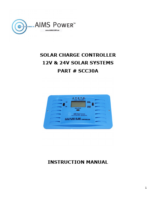
SOLAR CHARGE CONTROLLER 12V & 24V SOLAR SYSTEMSPART # SCC30AINSTRUCTION MANUALIMPORTANT SAFETY INSTRUCTIONSWARNING – BATTERY HANDLINGWorking near lead acid batteries is dangerous. Batteries generate explosive gases during normal battery operation.PERSONAL SAFETY PRECAUTIONSWear proper eye and clothing protection when working with lead acid batteries.Make sure that someone is within range of your voice to come to your aid if needed while you work with or are near lead acid batteries.Have plenty of fresh water and soap nearby for use in case battery acid contacts your eyes, sin or clothing. If this happens, wash immediately with soap and water. Then seek medical attention.Avoid touching your eyes while working with a battery. Acid particles (corrosion) may get into your eyes. If this occurs, flush eyes immediately with running cold water for at least 10 minutes. Then immediately seek medical attention.Never charge a frozen battery.Remove personal metal items such as rings, bracelets, necklaces, and watches when working with a battery. A battery produces a short-circuit current high enough to weld any metal objects and will cause a severe burn.Do not drop a metal tool on the battery. The resulting spark or short-circuit on the battery will cause an explosion.Never smoke or allow a sparks or flames near the battery.Neutralize any acid spills thoroughly with baking soda before attempting to clean up.NOTE: We recommend using AGM, GEL, or sealed lead deep cycle batteries especially in poorly ventilated areas. Not compatible with lithium batteries.The solar charge controller is designed to regulate the charge voltage to your 12 Volt or 24 Volt battery(s) from the solar panels. The controller provides protection against overcharge and battery reverse polarity connection. The unit includes a convenient LCD display, which shows charge current and battery voltage.FRONT PANEL FUNCTIONSLED IndicatorsPower: Solar power has sufficient voltage and connect to the battery(s) LED green.Charging: Indicates the solar power is charging the battery(s).Float: Indicates battery is full and charger is maintaining the charge.Battery reverse: LED yellow when battery connections are reversed.Protection: LED red when temperature of heat sink is up to @ 140°F and LED off when temperature drops down to @ 131°F.Switch24V / 12V selection switch: Set to 12V or 24V battery (s).Battery type switch: Set battery type being charged.Battery check button: When this button is pressed and held the battery voltage with display.INSTALLATIONInstall the charge controller near the battery(S) on a stable surface. This surface should be solid, even, dry and nonflammable. The battery cable should be as short as possible and have a cable diameter size to minimize loss, e.g. 4 mm² at 20 A and 6ft in length (16 AWG).Do not install the controller in direct sunlight.To ensure adequate airflow around the controller, allow a 4 inch clearance around the unit. The temperature at the installation site may never fall below or exceed the maximum permitted ambient temperature range.Connect the individual components according to the labels on the bottom of the controller. CONNECTION DIAGRAM (BOTTOM VIEW OF CONTROLLER)12 Volt24 Volt*Recommended wire = 10 AWG high quality cable*There are no user serviceable parts inside the charge controller. Do not disassemble or attempt to repair the unit. Contact manufacturer.SPECIFICATIONS Specification @ 12V @ 24VMax Solar Panel Array 400W 800WInput Voltage 16.5V-22V 33V-40VMax Voc 25V +/-1V 45V +/-1VMax Charging Current 30A +/- 3A 30A +/- 3AVoc Sealed: 14.55V +/-0.5V Flooded: 14.65V +/-0.5V Sealed: 29.15V +/-0.5V Flooded: 29.5V +/-0.5VVmp Sealed: 14.8V +/-0.5V Flooded: 14.78V +/-0.5V Sealed: 31.8V +/-0.5VFlooded: 31.7V +/-0.5V Output Voltage Sealed: 14.6V +/-0.5V Flooded: 14.8V +/-0.5V Sealed: 29.2V +/-0.5VFlooded: 29.6V +/-0.5V Floating Voltage Sealed: 13.7V +/-0.5V Flooded: 13.8V +/-0.5V Sealed: 27.4V +/-0.5VFlooded: 27.6V +/-0.5VOutput Low Voltage Protection <7.5V <15VOvertemp Protection Yes YesBattery Polarity Protection Yes YesOutput Short Circuit Protection Yes YesOperating Temperature 0°F - 104°F 0°F - 104°FStorage Temperature 14°F - 158°F 14°F - 158°FDimensions 7"L x 4"W x 1.25"H 7"L x 4"W x 1.25"HWeight .6lb .6lbAIMS Power offers a 1 year limited warranty.The following cases are not covered under warranty:1. Disassembled or tampering of any kind2. Incorrect or poor wiring3. Operation in a moist environmentAIMS Power Warranty Instructions:This product is designed using the most modern digital technology and under very strict quality control and testing guide lines. If, however you feel this product is not performing as it should, please contact us: **************************(775)359-6703.We will do our best to resolve your concerns. If the product needs repair or replacement, make sure to keep your receipt/invoice, as that will need to be sent back along with the package and RA# prepaid to AIMS. You have a full 1 year warranty from date of purchase.This warranty is valid worldwide with the exception that freight and duty charges incurred outside the contiguous 48 United States will be prepaid by customer.Except as provided above, AIMS makes no warranty of any kind, express or implied, including without limitation the implied warranties of merchantability and fitness for a particular purpose. In no event shall AIMS be liable for indirect, special or consequential damages. This warranty only applies to AIMS Power branded products. All other name brand products are warranted by and according to their respective manufacturer. Please do not attempt to return non-AIMS Power branded products to AIMS Power.For additional products such as:-Modified sine wave inverters-Pure sine wave inverters-Solar charge controllers-Generators-Inverter chargers with automatic transfer switches-Custom cut cables-Batteries-Solar panelsPlease visit our web site: Tofindoutwheretobuyanyofourproducts,youmayalsoe-mail:************************(775)359-6703.。
多转电动驱动器标准单元(同步器)说明书
OPEN by limit switching / CLOSE by torque switching • CTS and OTS act as overload protection for the whole stroke, they interrupt the
control circuit when reaching the actuator set tripping torque. • OLS interrupts the control circuit when reaching the valve open limit set position. • CTS interrupts the control circuit when closing (seating) the valve. Set the close
MADE BY 26/05/2016 NTS CHECKED 26/05/2016 VEN APPROVED 26/05/2016 JP
WD CK-CKR STD., MSM, 1PH, 2WCPT, HT24V, LIM+ALS,
TOR+ATS, NOIMP
range
FLTI-TURN ELECTRIC ACTUATOR, STANDARD UNIT (SYNCROSET), MECHANICAL SWITCH MECH. A.C. SINGLE PHASE
0/4-20mA CPT CURRENT POSITION TRANSMITTER, 2 WIRES
ANTI-CONDENSATION HEATER, 24 VDC
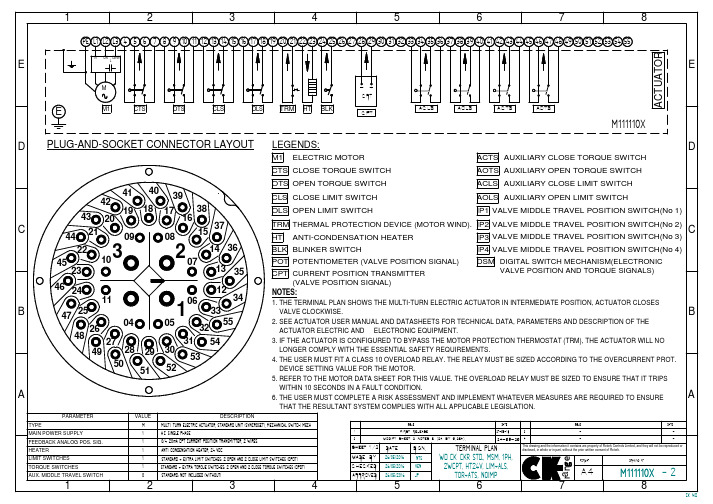
A NOTES: 1. THE TERMINAL PLAN SHOWS THE ELECTRIC ACTUATOR IN INTERMEDIATE POSITION, ACTUATOR CLOSES VALVE CLOCKWISE 2. SEE ACTUATOR USER MANUAL FOR TECHNICAL DATA, PARAMETERS AND DESCRIPTION OF THE ACTUATOR ELECTRIC AND ELECTRONIC EQUIPMENT.
TRIAC双向气动旋转活动器和配件说明书

CONTROLS A Division of A-T Controls, Inc.2Double acting and spring return Dual travel stopsTorques to 36,000 In-lbsDA and SR common end caps ISO 5211 / DIN 3337 mounting pad dimensionsWide base for direct mount to many butterfly valvesSubstantial pinion bearings mean high cycle lifeCorrosion resistant hard anodized finishEach unit serializedVDI/VDE 3845 accessory mounting configurationCustom accessory mountingNAMUR solenoid mounting padFEATURESSee accessory page for detailsTRIAC ® pneumatic actuators are designed and manufactured to provide the highest cycle-life on the market. We can accessorize them to accomplish virtually any control requirement. They are available with various mounting dimension configurations and span eleven models for appropriatetorque compatibility. Our extensive inventory and engineeringcapabilities allow us to respond to your needs with flexibility. We pride ourselves on exceeding customer expectations. Contact us forapplication assistance.0425II 2 GD c IICTorque Curves Double Acting OperationCCWAir is supplied to Port A forcing the pistons away from each other (toward ends), rotating drive pinion counterclockwise and exhausting air out of Port B.CWAir is supplied to Port B forcing the pistonstoward each other (toward center), rotating drive pinion clockwise and exhausting air out of Port A.Spring Return OperationCCWAir is supplied to Port A forcing the pistons away from each other (toward ends), rotating drive pinioncounterclockwise, compressing springs and exhausting air out of Port B.FAIL CWAir failure (loss of pressure) allows compressed springs to force pistons toward each other (toward center), rotating drive pinion clockwise and exhausting air out of Port A.*(Unit is capable of failure in counterclockwise direction by reversing pistons inside of housing.)TR10-2R1750Rack & Pinion Design% OF TORQUE2R2500-2R3500Scotch Yoke Design% OF TORQUEGENERALTECHNICAL DATA• Standard working temperature -5°F to 175°F • Low temperature and high temperature option • Maximum working pressure 150 psig• Operating media - clean, dry air, non-corrosive gas or light hydraulic oil• Air supply 40 psi - 150 psi • Rotation 100°• Dual travel stops standard • Mounting dimensions• A ccessories to NAMUR - VDI/VDE 3845• V alve mounting to ISO 5211 (TR10 - 2R3500)• C ustom configurations available in quantity • Permanently lubricated unitsTORQUE OUTPUTAND OPERA TION INFORMA TION SPRING RETURN TORQUE(In-lbs)TORQUE OUTPUTAND OPERA TION INFORMA TION6Air Consumption (scf per 90 Deg)=xVolume 1,728Supply Pressure + 14.714.7DIMENSIONSTR10-2R1750TR10 & TR20 have travel stops located in the End Caps for travel adjustment in one direction. 2R40 & 2R80 have travel stops on the opposite side as shown. Direct Acting:Pressure at port P1 will result in a clockwise rotationPressure at port P2 will result in a counter clockwise rotation Reverse Acting:Pressure at port P1 will result in a counter clockwise rotation Pressure at port P2 will result in a clockwise rotationNOTES: Accessory mounting holes are not intended for Manual Gear Overrides or StopBlocks. Cycle times are under no load conditions. Air line size, air capacity, and valve torque characteristics affect these cycle times. Faster or slower cycle times can be accomplished using special control components.WEIGHT (POUNDS)VOLUME (CU. IN. PER 90 DEG)CYCLE TIMES (SEC. PER 90 DEG)DIMENSIONS 2R2500-2R35008PART #TKA-012PART #TKA-010PART #TKA-020PART #TKA-030PART #TKA-040PART #TKA-050REQUIRED FOR 2" & 3"REQUIRED FOR 4"FOR 2" & 3"REQUIRED REQUIRED FOR 4"FOR 5" & 6"REQUIRED FOR 8"REQUIRED Adapter Dimensions for 2K SeriesDimensions – 2K SeriesRefer to valve dimensions for actual sizingOther inserts are available on request.2K402K80 - 2K2002K300 - 2K1200Note: 2K850 and 2K1200 have only 5" bolt circleDIRECT MOUNTFOR BUTTERFL Y VAL VES9DIRECT MOUNT ACTUA TORSFOR CENTERLINE BUTTERFL Y VALVESInserts for use with 2R Series Actuators(Refer to V sq. dimension on page 6)Note:»The 2CI Series actuators have five springs per side. »The final number(s) in the 2CI model numbers refers to the size of the Butterfly Valve body for mounting.Aluminum or Stainless Steel housing Weatherproof/explosion proof Captive bolts Many switch options AS-I systems Can be mounted on manual valvesAll Accessory Options AvailableTVCS-X411-4NDirect Mount SolenoidsACCESSORIESAPL-510NCSA ApprovedClass I, Div 1 & 2, Groups B, C, DAPL-310NCSA Approved, Type 4XAPL-210NCSA Approved, Type 4XSee brochure for details & optionsAPL-910NStainless Steel Type 4X, IP 67Lock-up valves Filter regulators Special tubing/fittings Lockout/tagout hardware Flow controls Speed controlsCustom assemblies Dribble control SpecialsComplete mounting and assembly serviceOther Accessories and ControlsSee stainless steel actuatorbrochure for detailed information.See 180° Pneumatic Rack & Pinion brochure for details.PPR, EPR &SS “Smart” Series2R, 2C, and 2K DGO SERIESDeclutchable Gear OverridesPositioners12SPECIFICA TION ANDORDERING INFORMA TIONSample SpecificationActuators shall be of rugged pneumatic Rack & Pinion Design. Actuator body should be hard anodized to promote long cycle life and corrosion resistance. The actuator body shouldincorporate a heavy duty, ISO 5211 valve mounting pad with multiple ISO FO bolt circles for ease of mounting. Actuator internals should include dual aluminum pistons for a balanced torque load and a one-piece plated blow-out proof pinion for operator safety. Actuator drive pinions should incorporate significant body housing bearings with heavy duty O-Ring seals to promote high cycle life. The unit should have a dual travel stop feature, with a minimum of 5° of stroke adjustment on both ends of travel, to accommodate numerous valve and damper designs. All actuator fasteners and hardware should be stainless steel for corrosion resistance. The rack & pinion actuator line should be offered in a broad range of torque outputs. The actuator of choice should be A-T Controls (TRIAC ®) TR/2R Series Rack & Pinions.Viton ® is a registered trademark of E.I. DuPont de Nemours.2Triac Rack & Pinion Actuator with double travel stopsTTriac Rack & Pinion Actuator with single travel stop (TR10DA, TR20DA, TR20SA only)R ISO / DIN mounting configuration CI Direct mount to Centerline BFV**K Direct mount to Keystone / ABZ / Ultraflow BFV N DDirect mount to Nibco BFV (special order: CF)Direct mount to Demco BFV (special order: CF)Note: Others available, call for details0000Actuator size (10, 20, 40, 80, 130, 200, 300, 500, 850, 1200, 1750, 2500, 3500)DA Double acting configurationDAR Double acting (reverse acting) configuration SR Spring return fail clockwise configurationSOSpring return fail counter-clockwise configuration Blank Standard Buna seals (-5˚F to 175˚F)V Viton ®seals (0˚F to 300˚F)LTLow temperature Buna seals (-45˚F to 175˚F)Blank5 springs per side (SR & SO only) (See pg 9 for 2CI model numbers)0Specify number of springs per side (1-6) (SR & SO only) (See pg 9 for 2CI model numbers)EExtra long travel stopsExample : 2R80SRE (TRIAC Model 80 Rack & Pinion Actuator with Travel Stop in both directions, Spring Return fail clockwise, with Extra long travel stops)TRIAC Model Number Matrix**Note: When ordering a 2CI actuator, please specify the valve size per the 2CI model numbers on page 9.Silicone seals (-45°F to 175°F)OPERA TIONAL DETAILS AND FEA TURESEXPLODED VIEW AND BILL OF MA TERIAL14Weatherproof enclosure ISO 5211 mounting kits On-off or modulatingCSA approvedFail-Safe ElectricsTorques to 410,000 in-lbs Declutchable gear overrides ISO 5211 and other mounting Custom mounting availableAutomated Valve AssembliesCustom Mounting and Assembly ServiceHeavy Duty ActuatorsSpring ReturnFeatures stabilizer bar for longer cycle life Torques to 1,600,000 in-lbs Easy accessory mounting Symmetric & Canted YokePneumatic or Electric Pre-engineered assemblies Pre-sized and pre-priced Double Acting or Spring Return Multi-port valves Various End Connection Options150#, 300# and 600# flanged Sanitary endsFiresafe valves and more Tank bottom valves Segmented Control Valves Butterfly Valve packages FM Approved Assemblies15Complete Valve AutomationSee our website for IOM’s & 3D models!9955 International Blvd.Cincinnati, Ohio 45246PH (513) 247-5465FAX (513) 247-5462。
电子检测器旋转推动器双插线电路板说明书
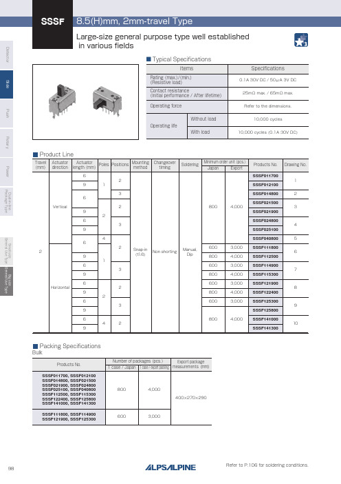
DetectorSlidePushRotaryPowerDual-in-line Package TypeSmall size General Use Type Big size General Use TypePC board mounting hole dimensions(Viewed from direction A)8.57}Operating force with detent : 2.2Nb J a b J c: shaft length14.53NTravelPC boardmounting face Terminal No.1233.30.52215.50.352.5222a b c }a Jbc J bA15.3222.510-ø0.7 hole1.5 1.51.62242-pole, 3-position15.514.5Travel PC boardmounting faceTerminal No.1233.38.52270.352.50.5R Operating force with detent : 2.5NAr : shaft length32-pole, 2-position15.3222.56-ø0.7 hole1.5 1.51.6DimensionsUnit:mmStyleNo.8.57}Operating force with detent : 2.2N b ab c : shaft length14.53NTravelPC boardmounting face Terminal No.1233.30.52215.50.352.5222a b c }a bc bA15.3225-ø0.7 hole1.5 1.51.6221.2521-pole, 3-positionTravelPC boardmounting faceTerminal No.1Operating force with detent : 2.5N233.38.52215.50.5R A71.250.35r : shaft length14.511-pole, 2-position15.3223-ø0.7 hole1.51.51.61.25Vertical Actuator Type17.570.352.5PC boardmounting faceTerminal No. 1Operating force with detent : 2.5N233.38.5222220.5RATravel16.5r : shaft length17.3212-ø0.7 hole1.5 1.51.62222.5254-pole, 2-positionSSSF/8.5(H)mm, 2mm-travel TypeDetectorSlide Push Rotary Power Dual-in-line Package Type Small size General Use Type Big size General Use TypeStyle15.3222.56-ø0.7 hole1.5 1.51.68TravelPC boardmounting faceTerminal No. 1Operating force with detent : 2.5N22215.5353.38.50.5Ar: shaft length14.572.50.35RR-12-pole, 2-position15.3222.510-ø0.7 hole1.5 1.51.6229Travel22a b cPC boardmounting faceTerminal No. 1222215.5353.38.50.5Operating force with detent :3N}}2.2NA: shaft length14.572.50.35-12-pole, 3-position2212-ø0.7 hole1.5 1.51.62222.517.310TravelPC boardmounting faceTerminal No.Operating force with detent : 2.5N22217.5353.38.52220.5172.50.35RR-1Ar: shaft length16.54-pole, 2-positionNo.PC board mounting hole dimensions(Viewed from direction A)15.3225-ø0.7 hole1.5 1.51.6221.257Travel22a b cPC boardmounting faceTerminal No. 1222215.5353.38.5Operating force with detent :2N3N} }0.5A0.351.257-1: shaft length14.51-pole, 3-position6TravelPC boardmounting faceTerminal No. 1Operating force with detent : 2.5N22215.5353.38.50.5A0.351.257RR-1r: shaft length14.51-pole, 2-position15.3223-ø0.7 hole1.5 1.51.61.25Horizontal Actuator TypeDimensionsUnit:mm8.5(H)mm, 2mm-travel TypeSSSFDetectorSlidePushRotaryPowerDual-in-line Package TypeSmall size General Use Type Big size General Use TypeSSSF/8.5(H)mm, 2mm-travel Typec123Circuit Diagram(Viewed from Direction A)1-pole, 2-position Drawing No.1, 6cc123451-pole, 3-position Drawing No.2, 7c c1234562-pole, 2-position Drawing No.3, 8c c c c123456789!02-pole, 3-position Drawing No.4, 9c c cc123456789!1!2!04-pole, 2-position Drawing No.5, 1090˚2.50.050.30.60.60.60.330.05Actuator ConfigurationUnit:mmThickness of PC board t=1.62-R 0.7R0.751.53AShape of Frame LegUnit:mm1 - 21 - 32 - 22 - 34 - 215.515.517.517.5APole - positionVerticalHorizontalDetectorSlide Push Rotary Power Dual-in-line Package Type Small size General Use Type Big size General Use Type300200100A max.BDCETime (s)F max.Pre-heatingRoomtemperatureTemperature(C)1. The condition mentioned above is the temperature on the mounting surface of a PC board. There are cases where thePC board’s temperature greatly differs from that of the switch, depending on the PC board’s material, size, thickness, etc.The above-stated conditions shall also apply to switch surface temperatures.2. Soldering conditions differ depending on reflow soldering machines. Prior verification of soldering condition is highlyrecommended.NotesExample of Reflow Soldering Condition1. Heating method: Double heating method with infrared heater.2. T emperature measurement: T hermocouple φ0.1 to 0.2 CA (K)or CC (T)at soldering portion (copper foil surface).A heat resisting tape should be used for fixed measurement.3. Temperature profileSlide Switches / Soldering ConditionsSSSS8SSSS7SSACSoldering temperature Duration of immersionPreheating temperature Preheating timeSSAG, SSAJ, SSALSSSS9SSSS2SSSF, SSSUSeriesSeries3+1/0s4s max.3s max.3s max.3s max.3s max.2s max.ItemsSoldering timeDip solderingSSSS9SSSS2120℃ max.100℃ max.100℃ max.100℃ max.60s max.60s max.60s max.60s max.260±5℃260±5℃5+0/-1s (2 times)3±1s SSSF, SSSU260±5℃10±1s/5±1s SSAC260±5℃5±1s Reference for Hand SolderingReference for Dip Soldering(For PC board terminal types)330±5℃320±5℃300±10℃350±10℃350±10℃350±10℃350±5℃Soldering temperatureSSSS2Vertical1-pole, 3-positionVertical1-pole, 2-positionHorizontal1-pole, 2-position1-pole, 3-position2-pole, 3-positionSSAG, SSAJ, SSAL, SSSS8, SSS7260150 Series(Reflow type)26025023040180120A(℃)3s max.B(℃)C(s)D(℃)E(℃)F(s)。
MECQ1 系列 技術手冊说明书

CONTROLLERMECQ1 系列技術手冊目錄1.安全須知 (4)1-1.注意事項 (4)1-2.安裝注意事項 (5)2.規格 (6)2-1.特性表 (6)2-2.控制器尺寸 (7)2-3.馬達規格 (7)3.系統配置 (8)3-1.MECQ1的配置 (8)3-2.外部接線圖 (9)4.MECQ1的外部名稱和功能設定 (10)4-1.外觀和零件名稱 (10)4-2.LED狀態顯示 (10)4-3.網路ID指示 (11)4-4.控制器ID選擇開關(SW1) (11)4-5.通訊速度和終端電阻選擇開關(SW2) (12)4-6.連接器(CN1~CN5) (13)5.I/O 控制信號 (14)5-1.信號電纜 (14)5-2.電路連接 (15)5-3.輸入信號 (17)5-4.輸出信號 (26)6.操作 (29)6-1.電源同步 (29)6-2.操作「伺服開啟」 (29)6-3.操作模式 (29)7.其他操作功能 (31)7-1.位置表(PT)操作範例 (31)7-2.吋動操作範例 (32)7-3.原點復位 (33)7-4.停止操作 (36)7-5.觸發脈衝的輸出 (36)7-6.推力動作功能 (38)8.通訊功能 (41)8-1.與PC電腦連接 (41)8-2.通訊界面電路 (42)9.參數 (43)9-1.參數表 (43)9-2.參數說明 (44)10.保護功能 (50)3安全須知10-1.警報類型 (50)10-2.獲取警報資訊 (50)10-3.檢查和解除警報 (51)10-4.警報履歷功能 (52)4 安全須知1.安全須知操作前●感謝您購買金器MECQ1產品。
●MECQ1採用32位元高性能ARM晶片,是一款全方位的數位定位控制器。
●本手冊將說明MECQ1的處理、維護、修理、診斷和故障排除。
●在操作MECQ1之前,請仔細閱讀本手冊以確保安全。
●閱讀完本手冊後,請置放於四周,以便使用者在需要時取用。
- 1、下载文档前请自行甄别文档内容的完整性,平台不提供额外的编辑、内容补充、找答案等附加服务。
- 2、"仅部分预览"的文档,不可在线预览部分如存在完整性等问题,可反馈申请退款(可完整预览的文档不适用该条件!)。
- 3、如文档侵犯您的权益,请联系客服反馈,我们会尽快为您处理(人工客服工作时间:9:00-18:30)。
转动极板控制器使用手册杭州天明电子有限公司版本:V1.3目录1. 概述 (3)1.1.系统结构 (4)1.2.产品特性 (5)2. 使用条件 (6)3.移动极板控制器使用说明 (7)4 TM-Z触摸屏页面描述 (13)4.1触摸屏菜单结构 (13)4.2页面描述 (14)4.2.1【欢迎页面】 (14)4.2.2【运行状态】 (15)运行状态子菜单一:冷却风扇运行状态 (15)运行状态子菜单二:变频电机运行状态 (16)运行状态子菜单三:变频器运行状态 (17)运行状态子菜单四:辅助输入状态 (18)4.2.3【启停控制】 (19)系统登录: (19)启停控制子菜单:变频回路启停 (20)4.2.4【参数设置】 (21)参数设置子菜单一:工作参数设置 (21)参数设置子菜单二:闭环控制设置 (25)参数设置子菜单三:系统参数设置 (26)参数设置子菜单四:参数备份恢复 (28)4.2.5【故障报警】 (29)故障报警子菜单一:当前故障状态 (29)故障报警子菜单二:历史报警记录 (31)4.2.6【?▼】 (31)5 安装与调试 (32)5.1 安装 (32)5.2 调试 (32)6 故障处理 (33)7 参数列表 (34)附录TM-Z与变频器接口示意图 (37)1. 概述随着我国环保领域对节能减排要求指标的日益严格,直接推动了大量有价值新技术应用。
作为一种有效地节能减排方式,我公司研发转动极板除尘技术有美好的应用前景。
同时TM系列工频控制器、TM-HFHV高频高压电源作为我公司主力应用于静电除尘器领域的专用电源,也在国内处于领先地位。
为了将这两项先进技术更加紧密衔接并协同工作,发挥更大的潜力,为客户提供完整的全套解决方案,通过智能/人工控制的方式,调节启停、调速等手段来控制移动极板范畴内的转动电机和刷子电机(统称为变频电机),达到适宜工况的变频电机启停状态和转速,来实现更好的排放效果和节能效果。
转动极板控制器(TM-Z)就是TM系列控制器和高频高压电源等衔接转动极板除尘技术的桥梁和执行机构。
1.1.系统结构移动极板控制系统如下图1-1所示,TM-Z控制器通过交换机和上位机进行连机通信,一台触摸屏最多和16台TM-Z控制器进行通信。
并且每台TM-Z控制器可连接最多6路变频器,及变频电机的冷却风扇。
图1-1 系统结构1.2. 产品特性移动极板控制器(以下统称:TM-Z)具有以下特点:核心控制逻辑采用先进的32位DSP数字信号处理器,具有处理能力强,响应速度快,可靠性好等优点。
网络通信模块采用韩国WIZnet公司的W5300网络芯片,内部集成10/100M以太网控制器,MAC和TCP/IP协议栈。
使用方便、稳定可靠,广泛应用于高性能、低成本的Internet嵌入式领域。
提供RS485通讯接口,和触摸屏进行通讯,用以控制设备的启停,参数的显示/设置和运行方式的切换,报警/故障的显示,实现现场级监控。
一台触摸屏最多可连接16台TM-Z控制器,通过拨码开关设置识别各控制器地址。
提供以态网接口,和上位机进行通讯。
可通过工业以太网进行工厂级监控,降低维护成本。
提供6路电机调速模拟量输出信号:0~10V恒电压。
输出6路变频器的启停信号、6路变频电机冷却风扇的启停信号。
接收6路变频器故障反馈、6路变频电机运行状态反馈、6路电机冷却风扇运行状态反馈等信号。
接收6路辅助输入信号,比如:高料位连锁反馈等。
实时时钟。
可以显示/修改当前年月日和时分秒。
断电保持功能。
设定的参数断电后予以保存,无需重新设定。
2. 使用条件使用的环境温度为0~40℃。
空气最大相对湿度不超过90%(在相当于空气温度20±5℃时)。
控制器周围的气体应无导电尘埃,和含有腐蚀金属或绝缘材料的气体或蒸汽存在。
非爆炸性危险工作环境,控制器周围无剧烈震动和冲击,且垂直倾斜度不超过5%。
主回路输入的交流电压应符合以下规定:波形为正弦波,适合任意频率,波动范围不超过±2%;电压为380V,其幅度变化不超过±5%,瞬时波动范围不超过±10%。
控制器供电电压为DC/AC 24V瞬时波动范围不超过±10%。
3.移动极板控制器使用说明3.1 TM-Z控制器外观图JD1 JM1图3-1 TM-Z控制器外观图(正视图)J1 J2 DC1 DC2DC3 SK1 SM13.2 端口说明及接口定义3.2.1 端口说明:J1:电源输入输出及变频电机速度信号输出J2:变频器故障、电机运行状态、冷却风扇运行状态,料位机状态及备用反馈输入J3:变频电机、电机风扇的启停信号输出及485通信端口SM1:远控、近控切换开关SK1:控制器地址拨码开关,4位JM1:触摸屏接口JD1:以态网接口DC1~DC3:电源指示灯,控制器正常运行灯,报警灯3.2.2 接口定义:J1:1~24按照正视图方向,从板子内侧即左边一列由上到下依次为1~12号端子,右边一列由上到下依次为13~24号端子。
J2:25~72按照正视图方向,从板子内侧即左边一列由上到下依次为25~48号端子,右边一列由上到下依次为49~72号端子。
J3:73~100按照正视图方向,从板子内侧即上面一行由右到左依次为73~86号端子,下面一行由右到左依次为87~100号端子。
端子的接口定义见“表5-1 TM-Z控制器接口定义”。
TM-Z控制器接口定义注[1]:当输出继电器吸合时,继电器触点把提供输出电压的输入端口与输出端口短路,故输出端口与输入端口同电位,均为DC 24V;当输出继电器释放时,继电器触点把输入端口与输出端口断开,两者之间通过压敏电阻连接,故输出端口为高阻态。
4 TM-Z触摸屏页面描述4.1 触摸屏菜单结构上电前,请确保TM-Z控制器和触摸屏可靠连接,然后上电,若要求屏幕校正,请按提示进行操作,校正完毕后进入在线控制器列表;点击需要操作的控制器地址,进入到主界面。
控制器菜单结构如图4-1所示。
图4-1 控制器菜单结构4.2 页面描述4.2.1【欢迎页面】欢迎页面如图所示。
欢迎页面自上而下为:总菜单、欢迎主界面、状态栏总菜单包括:运行状态、启停控制、参数设置、故障报警、其他等,可分别对其进行触摸操作,并弹出相应子菜单。
状态栏包括:返回列表按钮,控制器地址,正常/故障状态显示,远控/近控状态显示,时间显示。
4.2.2【运行状态】运行状态子菜单一:冷却风扇运行状态页面的进入欢迎页面→点击“运行状态”菜单→点击“冷却风扇运行状态”子菜单→进入“冷却风扇运行状态及反馈”页面。
页面内容该页面显示内容包括6路冷却风扇的实时运行状态及反馈信息。
页面的进入欢迎页面→点击“运行状态”菜单→点击“变频电机运行状态”子菜单→进入“变频电机运行状态及反馈”页面。
页面内容该页面显示内容包括6路变频电机的实时运行状态及反馈信息。
页面的进入欢迎页面→点击“运行状态”菜单→点击“变频器运行状态”子菜单→进入“变频器运行状态反馈”页面。
页面内容该页面显示内容包括6路变频器的实时运行状态。
页面的进入欢迎页面→点击“运行状态”菜单→点击“辅助输入状态”子菜单→进入“辅助输入状态”页面。
页面内容该页面显示内容包括6路辅助输入的实时状态。
4.2.3【启停控制】系统登录:在以下的某些菜单的使用过程中,特别是需要更改参数设置的菜单,点击进入前需要进行系统登录,输入用户密码并确认,以防止误操作,并带来某些安全隐患。
初始密码为:000000启停控制子菜单:变频回路启停页面的进入欢迎页面→点击“启停控制”菜单→点击“变频回路启停”子菜单→进入“变频回路启停控制”页面。
页面内容该页面显示内容包括6路风扇及6路变频电机的启动\停止控制,点击“启动”或者“停止”,能够对相应的设备进行控制。
4.2.4【参数设置】参数设置子菜单一:工作参数设置第一页页面的进入欢迎页面→点击“参数设置”菜单→点击“工作参数设置”子菜单→进入“调速控制模拟输出值设置”页面。
页面内容该页面显示内容为6路变频电机的输出模拟值设定,设定值:1%~100%,点击“保存设置”进行参数保存,点击“>>”进入下一页。
第二页页面的进入欢迎页面→点击“参数设置”菜单→点击“工作参数设置”子菜单→进入“调速控制模拟输出值设置”页面→点击“>>”进入“风扇控制方式设置”菜单。
页面内容该页面显示内容为6路冷却风扇的运行方式设定,设定值:自控\联控。
自控为独立控制方式,人工设定风扇的启停,不受相应电机的运行状态控制;联控为受控方式,受电机运行状态的影响,电机运行,则风扇也运行,电机停止,则风扇也停止。
点击“保存设置”进行参数保存,点击“>>”进入下一页。
第三页页面的进入欢迎页面→点击“参数设置”菜单→点击“工作参数设置”子菜单→进入“调速控制模拟输出值设置”页面→点击“>>”进入“风扇控制方式设置”菜单→点击“>>”进入“辅助输入使能设置”菜单。
页面内容该页面显示内容为6路辅助输入的使能设置,设定值:使能\禁止使能,来确定是否接收辅助输入信号的反馈,点击“保存设置”进行参数保存。
第四页页面的进入欢迎页面→点击“参数设置”菜单→点击“工作参数设置”子菜单→进入“调速控制模拟输出值设置”页面→点击“>>”进入“风扇控制方式设置”菜单→点击“>>”进入“辅助输入使能设置”菜单→点击“>>”进入“变频回路使能设置”菜单页面内容该页面显示内容为6路变频回路的使能设置,设定值:使能\禁止使能,点击“保存设置”进行参数保存。
页面的进入欢迎页面→点击“参数设置”菜单→点击“闭环控制设置”子菜单→进入“闭环控制设置”页面页面内容该页面显示内容包括:控制方式选择、控制器类型、采样IP设置、采样时间值,控制器在线状态,最小调速值,当前调速值,采样电压值,采样电流值等。
点击相应的方框,便可对其进行操作。
页面的进入欢迎页面→点击“参数设置”菜单→点击“系统参数设置”子菜单→进入“系统参数设置”页面页面内容该页面显示内容包括:控制器IP地址、控制器网关地址、系统日期、系统时间、屏幕校正、修改密码等内容。
点击相应的方框,便可对其进行操作。
以设置控制器IP地址为例:光标(白底黑字)位置可通过下面的数字键进行设置,通过“<<<”,“>>>”键可对IP地址的不同段进行切换,输入设定IP后,按“确定”键返回,若未进行更改操作,也可按“返回”键返回。
参数设置子菜单四:参数备份恢复页面的进入欢迎页面→点击“参数设置”菜单→点击“参数备份恢复”子菜单→进入“参数备份恢复”页面页面内容该页面显示内容包括:“保存”当前设置参数、“备份”当前设置参数、“加载”之前备份参数、“恢复”出厂默认参数等内容。