e500
林芬电子Power Wave E500操作手册说明书

Operator’s ManualRegister your machine:/registerAuthorized Service and Distributor Locator: /locatorIM10370-A| Issue D a te Oct-16© Lincoln Global, Inc. All Rights Reserved.For use with machines having Code Numbers:12643Save for future referenceDate PurchasedCode: (ex: 10859)SECTION A:WARNINGSC ALIFORNIA PROPOSITION 65 WARNINGSWARNING: This product, when used for welding or cutting, produces fumes or gases which contain chemicals known to the State of California to cause birth defects and, in some cases, cancer. (California Health & Safety Code § 25249.5 et seq.)ARC WELDING CAN BE HAZARDOUS. PROTECTYOURSELF AND OTHERS FROM POSSIBLE SERIOUS INJURY OR DEATH. KEEP CHILDREN AWAY.PACEMAKER WEARERS SHOULD CONSULT WITH THEIR DOCTOR BEFORE OPERATING.Read and understand the following safety highlights. For additional safety information, it is strongly recommended that you purchase a copy of “Safety in Welding & Cutting - ANSI Standard Z49.1” from the American Welding Society, P.O. Box 351040, Miami, Florida 33135 or CSA Standard W117.2-1974. A Free copy of “Arc Welding Safety” booklet E205 is available from the Lincoln Electric Company, 22801 St. Clair Avenue, Cleveland, Ohio 44117-1199.BE SURE THAT ALL INSTALLATION, OPERATION,MAINTENANCE AND REPAIR PROCEDURES ARE PERFORMED ONLY BY QUALIFIED INDIVIDUALS.FOR ENGINE POWERED EQUIPMENT.1.a.Turn the engine off before troubleshootingand maintenance work unless themaintenance work requires it to be running.1.b.Operate engines in open, well-ventilated areas or vent the engineexhaust fumes outdoors. 1.c.Do not add the fuel near an open flame weldingarc or when the engine is running. Stop the engine and allow it to cool before refueling to with hot engine parts and igniting. Do not spill fuel when filling tank. If fuel is spilled, wipe it up and do not start engine until fumes have been eliminated.1.d. Keep all equipment safety guards, coversand devices in position and in good repair.Keep hands, hair, clothing and tools away from V-belts, gears, fans and all other moving parts when starting, operating or repairing equipment.1.e.In some cases it may be necessary to remove safety guards toperform required maintenance. Remove guards only when necessary and replace them when the maintenance requiring their removal is complete. Always use the greatest care when working near moving parts. 1.f. Do not put your hands near the engine fan. Do not attempt tooverride the governor or idler by pushing on the throttle control rods while the engine is running. 1.g.To prevent accidentally starting gasoline engines while turningthe engine or welding generator during maintenance work,disconnect the spark plug wires, distributor cap or magneto wire as appropriate. 1.h.To avoid scalding, do not remove the radiatorpressure cap when the engine is hot.ELECTRIC ANDMAGNETIC FIELDS MAY BE DANGEROUS2.a.Electric current flowing through any conductorcauses localized Electric and Magnetic Fields (EMF).Welding current creates EMF fields around welding cables and welding machines 2.b.EMF fields may interfere with some pacemakers, andwelders having a pacemaker should consult their physician before welding. 2.c.Exposure to EMF fields in welding may have other health effectswhich are now not known. 2.d.All welders should use the following procedures in order tominimize exposure to EMF fields from the welding circuit:2.d.1.Route the electrode and work cables together - Securethem with tape when possible.2.d.2.Never coil the electrode lead around your body.2.d.3.Do not place your body between the electrode and workcables. If the electrode cable is on your right side, the work cable should also be on your right side.2.d.4.Connect the work cable to the workpiece as close as pos-sible to the area being welded.2.d.5.Do not work next to welding power source.SAFETYTABLE OF CONTENTS PRODUCT DESCRIPTION (3)EQUIPMENT LIMITATIONS (3)DESIGN FEATURES (3)INSTALLATION...............................................................................................................................................Section A TECHNICAL SPECIFICATIONS.....................................................................................................................................A-1MACHINE GROUNDING...............................................................................................................................................A-2LOCATION AND VENTILATION FOR COOLING .............................................................................................................A-2HIGH FREQUENCY PROTECTION.................................................................................................................................A-2LIFTING ............................................................................................................................................................A-2STACKING ............................................................................................................................................................A-2TILTING ............................................................................................................................................................A-2 ENVIRONMENTAL LIMITATIONS.................................................................................................................................A-2CASE FRONT CONTROLS...........................................................................................................................................A-3CASE BACK CONTROLS.............................................................................................................................................A-4 RECOMMENDED ELECTRODE AND WORK CABLE SIZES FOR ARC WELDING ..............................................................A-7CONTROL CABLE AND VOLTAGE SENSING CONNECTIONS..........................................................................................A-8TYPICA; INTEGRATED SYSTEMS (SINGLE ARM)..........................................................................................................A-9 OPERATION ..................................................................................................................................................Section BPOWER-UP SEQUENCE..............................................................................................................................................B-1DUTY CYCLE ............................................................................................................................................................B-2COMMON WELDING PROCEDURES............................................................................................................................B-3 ACCESSORIES................................................................................................................................................Section C MAINTENANCE...............................................................................................................................................Section DVISUAL INSPECTION..................................................................................................................................................D-1ROUTINE MAINTENANCE............................................................................................................................................D-1PERIODIC MAINTENANCE...........................................................................................................................................D-1 TROUBLESHOOTING.......................................................................................................................................Section EHOW TO USE TROUBLESHOOTING GUIDE...................................................................................................................E-1USING THE STATUS LED TO TROUBLESHOOT SYSTEM PROBLEMS............................................................................E-2ERROR CODES FOR THE POWER WAVE .....................................................................................................................E-3 DIAGRAMS ...................................................................................................................................................Section FParts List Content/details may be changed or updated without notice. For most current Instruction Manuals, go to.DESCRIPTION POWER WAVE®E500CONSTANT VOLTAGE WELDING Synergic CVFor each wire feed speed, a corresponding voltage is prepro-grammed into the machine through special software at the factory.The nominal preprogrammed voltage is the best average voltage for a given wire feed speed, but may be adjusted to preference.When the wire feed speed changes, the POWER WAVE ®E500automatically adjusts the voltage level correspondingly to maintain similar arc characteristics throughout the WFS range. Non Synergic CVIn non-synergic modes, the WFS control behaves more like a conventional CV power source where WFS and voltage areindependent adjustments. Therefore to maintain the arc charac-teristics, the operator must adjust the voltage to compensate for any changes made to the WFS.All CV ModesPinch adjusts the apparent inductance of the wave shape. The “pinch” function is inversely proportional to inductance.Therefore, increasing Pinch Control greater than 0.0 results in a crisper arc (more spatter) while decreasing the Pinch Control to less than 0.0 provides a softer arc (less spatter).PULSE WELDINGPulse welding procedures are set by controlling an overall “arc length” variable. When pulse welding, the arc voltage is highly dependent upon the waveform. The peak current, back ground current, rise time, fall time and pulse frequency all affect thevoltage. The exact voltage for a given wire feed speed can only be predicted when all the pulsing waveform parameters are known.Voltage or Trim can be adjusted.Trim adjusts the arc length and ranges from 0.50 to 1.50 with a nominal value of 1.00. Trim values greater than 1.00 increase the arc length, while values less than 1.00 decrease the arc length.(See figure B.3)M ost pulse welding programs are synergic. As the wire feed speed is adjusted, the POWER WAVE ®E500 will automatically recalculate the waveform parameters to maintain similar arc properties.The POWER WAVE ®E500 utilizes “adaptive control” tocompensate for changes in the electrical stick-out while welding.(Electrical stick-out is the distance from the contact tip to the work piece.) The POWER WAVE ®E500 waveforms are optimized for a 0.75” stick-out. The adaptive behavior supports a range of stick-outs from 0.50 to 1.25”. At very low or high wire feed speeds, the adaptive range may be less due to reaching physical limitations of the welding process.UltimArc™ Control adjusts the focus or shape of the arc.UltimArc™ Control is adjustable from -10.0 to +10.0 with a nominal setting of 0.0. Increasing the UltimArc™ Control increases the pulse frequency and background current while decreasing the peak current. This results in a tight, stiff arc used for high speed sheet metal welding. Decreasing the UltimArc™Control decreases the pulse frequency and background current while increasing the peak current. This results in a soft arc good for out of position welding. (See Figure B.4)FIGURE B.4FIGURE B.3POWER WAVE®E500ACCESSORIESPOWER WAVE®E500MAINTENANCEIf for any reason you do not understand the test procedures or are unable to perform the tests/repairs safely, contact yourIf for any reason you do not understand the test procedures or are unable to perform the tests/repairs safely, contact yourIf for any reason you do not understand the test procedures or are unable to perform the tests/repairs safely, contact yourIf for any reason you do not understand the test procedures or are unable to perform the tests/repairs safely, contact yourKEY PART NUMBER DESCRIPTIONQTY P-1084-A INDEX OF SUB ASSEMBLIES AR 1P-1084-C CASE FRONT ASSEMBLY AR 2P-1084-D DIVIDER PANEL ASSEMBLY AR 3P-1084-E BASE & CENTER ASSEMBLY AR 4P-1084-F CASE BACK ASSEMBLY AR 5P-1084-GWRAPAROUND ASSEMBLYARP r i n t e d 11/01/2016 a t 14:11:44. P r o d u c e d b y E n i g m a .P-1084-A.jpgr i n t e d 11/01/2016 a t 14:11:44. P r o d u c e d b y E n i g m a .KEY PART NUMBER DESCRIPTIONQTY 9SG8969CASE FRONT ASSEMBLY 119SG8959CASE FRONT 129SG8970NAMEPLATE 12A 9SG8970NAMEPLATE13A 9SS16656-4OUTPUT TERMINAL ASBLY 23B 9SCF000371#10-24X.50HHCS-FULL-GR2-314744A9SG6864-1NEGATIVE OUTPUT STUD COVER 19SS9225-100SELF TAPPING SCREW 29SS9262-184WASHER25A9SG6864-2POSITIVE OUTPUT STUD COVER 19SS9225-100SELF TAPPING SCREW 29SS9262-184WASHER 26A 9SS32107COVER PLATE16B 9SS9225-99SELF TAPPING SCREW 47A 9SG6525-3HANDLE17B 9SM24995REAR HANDLE SUPPORT BRACKET 17C 9SS9225-66SELF TAPPING SCREW 48A 9SS28626-5FEEDHEAD PC BD ASBLY 18B 9ST9187-13#10-24HLN-1817/1-NYLON INSERT 49SG8964MAIN CONTROL HARNESS 19A 9SS12021-72BOX RECEPTACLE SOLID SHELL 19B 9SS8025-96SELF TAPPING SCREW 29C9SS17062-11CABLE CONNECTOR CAP 19SCF000010#10-24HN 49SE106A-1LOCKWASHER 29SS26124GROUND REFERENCE 19SS28393-3OUTPUT SNUBBER ASBLY 19SS18858-5SUPPRESSOR ASBLY 111C 9SS9262-1PLAIN WASHER 111D 9SE106A-15LOCKWASHER 111E 9SCF000344HEX HD SCREW112A9SS30151POSITIVE OUTPUT STUD LEAD 19SS18858-5SUPPRESSOR ASBLY 19SS9262-1PLAIN WASHER1P r i n t e d 11/01/2016 a t 14:11:44. P r o d u c e d b y E n i g m a .KEYPART NUMBER DESCRIPTIONQTY 9SE106A-15LOCKWASHER 19SCF000344HEX HD SCREW113A 9SM19969-9ETHERNET RECEPTACLE BULKHEAD 113B 9SM19969-4ETHERNET RECEPTACLE COVER 1149SS28834-2LINE SWITCH LEAD ASSEMBLY 19SS9225-68THREAD FORMING SCREW (CUTTING)29SS9262-183PLAIN WASHER 29SS9225-66SELF TAPPING SCREW2169SM19969-16ETHERNET PATCH CABLE ASSEMBLY1r i n t e d 11/01/2016 a t 14:11:44. P r o d u c e d b y E n i g m a .P-1084-C.jpgP r i n t e d 11/01/2016 a t 14:11:44. P r o d u c e d b y E n i g m a .KEY PART NUMBER DESCRIPTIONQTY 9SG8962DIVIDER PANEL ASSEMBLY119SG7808DIVIDER PANEL19SM22062-2INPUT RECTIFIER ASSEMBLY 12A9SM15454-18INPUT RECTIFIER MODULE 19SS9262-3PLAIN WASHER 29SE106A-1LOCKWASHER29SS25930-5TORX BUTTON HEAD SCREW #10-24X.6222E 9SS24574-1INPUT HEATSINK 12F 9SS9262-98PLAIN WASHER 22G 9SE106A-2LOCKWASHER 22H 9SCF0000131/4-20X.625HHCS 23A 9SM25066AIR DEFLECTER19SS9225-68THREAD FORMING SCREW (CUTTING)24A 9SS28841GROUND LUG14B 9SS9225-45THREAD FORMING SCREW 14C 9ST9695-17LOCKWASHER159ST13260-4DECAL-EARTH GROUND CONN 169ST12380-4BUSHING 179ST12380-8BUSHING18A 9ST13637-6DIODE-BRIDGE35A400VF-W1-PH 18B 9SS9262-27PLAIN WASHER 18C 9SE106A-1LOCKWASHER 18D 9SCF000010#10-24HN19A 9SS13490-157CAPACITOR-ALEL24000100V+300/-10%19B 9SS11604-65SET SCREW29SS18250-955PLUG & LEAD ASBLY 19D 9SS9262-23PLAIN WASHER 29E 9SE106A-2LOCKWASHER 29F 9SCF0001981/4-28HN29SS22745-3CAPACITOR INSULATION 110B 9SS27974CAPACITOR BRACKET 110C 9SE106A-2LOCKWASHER 210D9SCF0000171/4-20HN 29SCF000010#10-24HN2r i n t e d 11/01/2016 a t 14:11:44. P r o d u c e d b y E n i g m a .KEY PART NUMBER DESCRIPTIONQTY 9SE106A-1LOCKWASHER112A 9SM26272RECONNECT PANEL ASSEMBLY 112B 9SS9225-68THREAD FORMING SCREW (CUTTING)313A 9SL16423-140 V BUS PC BD ASBLY113B 9ST9187-13#10-24HLN-1817/1-NYLON INSERT 414A 9ST11267-A INSULATOR 214B 9ST11267-B INSULATOR 29ST10728-77FUSE (4A)1169SS18491-1MOV ASBLY19SS18250-1074PLUG & LEAD ASBLY19SM26138AUXILIARY TRANSFORMER & THERMOSTAT ASSEM118A 9SS13000-129AUXILIARY TRANSFORMER 19ST13359-15THERMOSTAT118C 9SS9225-32THREAD FORMING SCREWS 418D9SS9262-98PLAIN WASHER49SS9225-68THREAD FORMING SCREW (CUTTING)2P r i n t e d 11/01/2016 a t 14:11:44. P r o d u c e d b y E n i g m a .P-1084-D.jpgr i n t e d 11/01/2016 a t 14:11:44. P r o d u c e d b y E n i g m a .KEY PART NUMBER DESCRIPTIONQTY 9SG8967BASE & CENTER ASSEMBLY 119SG7791BASE 12A 9SL13138CORNER CAP 42B 9SS9262-183PLAIN WASHER 42C 9SS9225-66SELF TAPPING SCREW 43A 9ST11267-A INSULATOR43B 9SS10404-127RESISTORWW100W1005%29SCF000191#10-24X7.50RHS 23D 9SS9262-27PLAIN WASHER 43E 9SE106A-1LOCKWASHER 23F 9SCF000010#10-24HN 24A 9SL16500CHOKE ASBLY14B 9SS9225-66SELF TAPPING SCREW 34C 9SS9262-98PLAIN WASHER35A 9SS31590CURRENT TRANSDUCER ASBLY 15B 9SS30871LEM SUPPORT15C 9SS8025-77SELF TAPPING SCREW 15D 9SS9225-66SELF TAPPING SCREW 19SL11452-8PLUG & LEAD ASBLY 26A 9SG7848TRANSFORMER ASBLY 16B 9SS9225-66SELF TAPPING SCREW 37A 9SM24999OUTPUT RECTIFIER ASBLY 17B9SS9225-66SELF TAPPING SCREW 29SS23730-3SPACER29SCF0000151/4-20X1.00HHCS 29SS9262-98PLAIN WASHER 29SE106A-2LOCKWASHER 299SS28206-13BRAIDED LEAD 110A 9SCF0000285/16-18X1.25HHCS 110B 9SS9262-30PLAIN WASHER 210C 9SE106A-3LOCKWASHER 110D9SCF0000295/16-18HN19SCF0000285/16-18X1.25HHCS 19SS9262-30PLAIN WASHER2P r i n t e d 11/01/2016 a t 14:11:44. P r o d u c e d b y E n i g m a .KEYPART NUMBER DESCRIPTIONQTY 9SE106A-3LOCKWASHER 19SCF0000295/16-18HN 112A 9SCF0000405/16-18X.75HHCS 112B 9SS9262-30PLAIN WASHER 112C 9SE106A-3LOCKWASHER 113A 9SCF0000285/16-18X1.25HHCS 113B 9SS9262-30PLAIN WASHER 213C 9SE106A-3LOCKWASHER 113D 9SCF0000295/16-18HN 114A 9SCF0000405/16-18X.75HHCS 114B 9SS9262-30PLAIN WASHER 114C 9SE106A-3LOCKWASHER115A 9SG8986SWITCHBOARD ASSEMBLY 115B9SS9225-66SELF TAPPING SCREW 29SS18250-1063PLUG & LEAD ASBLY1r i n t e d 11/01/2016 a t 14:11:44. P r o d u c e d b y E n i g m a .P-1084-E.jpgBase & Center AssemblyPower Wave E500 - 1264311P r i n t e d 11/01/2016 a t 14:11:44. P r o d u c e d b y E n i g m a .KEYPART NUMBER DESCRIPTIONQTY 9SG8992CASE BACK ASSEMBLY119SG7795CASE BACK 12A 9SM25055FAN12B 9SS25930-14M6 X 1.00 TBHS-FULL-4554439SM24995REAR HANDLE SUPPORT BRACKET 14A 9SG6525-3HANDLE14B 9SS9225-66SELF TAPPING SCREW 49SS18250-1062PLUG & LEAD ASBLY 16A 9SS30907RELAY SUPPORT 16B 9SS9262-3PLAIN WASHER 26C 9ST4291-A LOCKWASHER 26D 9SCF000042#8-32HN 279SS22752-46RATING PLATE 18A 9SS15122-15RELAY18B 9SS8025-98SELF TAPPING SCREW 29A 9SS19999CORD GRIP CONNECTOR 19B9ST14370-3CONDUIT LOCKNUT19SS9225-68THREAD FORMING SCREW (CUTTING)29SS9262-183PLAIN WASHER 29SS9225-66SELF TAPPING SCREW 211A 9SS29938RECONNECT PANEL COVER111B 9SS9225-68THREAD FORMING SCREW (CUTTING)4129ST13259-4GROUNDING DECAL112Power Wave E500 - 12643P r i n t e d 11/01/2016 a t 14:11:44. P r o d u c e d b y E n i g m a .P-1084-F.jpgPower Wave E500 - 1264313P r i n t e d 11/01/2016 a t 14:11:44. P r o d u c e d b y E n i g m a .KEYPART NUMBER DESCRIPTIONQTY 1A 9SG7801LEFT CASE SIDE11B 9ST10097-5SPEED GRIP NUT RETAINER 21C 9SS9225-66SELF TAPPING SCREW41D 9SS9225-68THREAD FORMING SCREW (CUTTING)61E 9SS9262-183PLAIN WASHER 229SG7802RIGHT CASE SIDE 13A 9SG7798ROOF13B 9SS9225-68THREAD FORMING SCREW (CUTTING)39SG8035WIRING DIAGRAM 159SS30277-2WARRANTY DECAL 169SS27368-4DECAL LE LOGO 279SS27468POWERWAVE LOGO 289SS20601-6WARNING DECAL199SS28039-2DECAL GREEN INITIATIVE114Power Wave E500 - 12643P r i n t e d 11/01/2016 a t 14:11:44. P r o d u c e d b y E n i g m a .P-1084-G.jpgPower Wave E500 - 1264315P r i n t e d 11/01/2016 a t 14:11:44. P r o d u c e d b y E n i g m a .ATENÇÃOJapaneseChineseKoreanArabicREAD AND UNDERSTAND THE MANUFACTURER’S INSTRUCTION FOR THIS EQUIPMENT AND THE CONSUMABLES TO BE USED AND FOLLOW YOUR EMPLOYER’S SAFETY PRACTICES.SE RECOMIENDA LEER Y ENTENDER LAS INSTRUCCIONES DEL FABRICANTE PARA EL USO DE ESTE EQUIPO Y LOS CONSUMIBLES QUE VA A UTILIZAR, SIGA LAS MEDIDAS DE SEGURIDAD DE SU SUPERVISOR.LISEZ ET COMPRENEZ LES INSTRUCTIONS DU FABRICANT EN CE QUI REGARDE CET EQUIPMENT ET LES PRODUITS A ETRE EMPLOYES ET SUIVEZ LES PROCEDURES DE SECURITE DE VOTRE EMPLOYEUR.LESEN SIE UND BEFOLGEN SIE DIE BETRIEBSANLEITUNG DER ANLAGE UND DEN ELEKTRODENEINSATZ DES HER-STELLERS. DIE UNFALLVERHÜTUNGSVORSCHRIFTEN DES ARBEITGEBERS SIND EBENFALLS ZU BEACHTEN.ATENÇÃOJapaneseChineseKoreanArabicLEIA E COMPREENDA AS INSTRUÇÕES DO FABRICANTE PARA ESTE EQUIPAMENTO E AS PARTES DE USO, E SIGA AS PRÁTICAS DE SEGURANÇA DO EMPREGADOR.CUSTOmER aSSISTaNCE POLICYThe business of The Lincoln Electric Company is manufacturing and selling high quality welding equipment, consumables, and cutting equipment. Our challenge is to meet the needs of our customers and to exceed their expectations. On occasion, purchasers may ask Lincoln Electric for advice or information about their use of our products. We respond to our customers based on the best information in our possession at that time. Lincoln Electric is not in a position to warrant or guarantee such advice, and assumes no liability, with respect to such information or advice. We expressly disclaim any warranty of any kind, including any warranty of fitness for any customer’s particular purpose, with respect to such information or advice. As a matter of practical consideration, we also cannot assume any respon-sibility for updating or correcting any such information or advice once it has been given, nor does the provision of information or advice create, expand or alter any warranty with respect to the sale of our products.Lincoln Electric is a responsive manufacturer, but the selection and use of specific products sold by Lincoln Electric is solely within the control of, and remains the sole responsibility of the customer. Many variables beyond the control of Lincoln Electric affect the results obtained in applying these types of fabrication methods and service requirements.Subject to Change – This information is accurate to the best of our knowledge at the time of printing. Please refer to for any updated information.。
E500内核MMU介绍
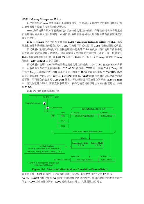
MMU(Memory Management Units)内存管理单元mmu是处理器的重要组成部分,主要功能是将程序使用的虚拟地址转换为处理器硬件能够直接访问的物理地址。
mmu为系统软件设立了转换查找表以支持虚实地址的映射。
在这些查找表中将规定虚实地址的对应关系及访问控制等一系列信息。
系统软件将利用处理器提供的查找表完成虚实地址的映射。
E500内核mmu中共使用两个查找表TLB0(translation lookaside buffer)和TLB1来实现虚拟地址和物理地址的转换。
其中TLB0用来进行页式映射,而TLB1用来实现段式映射。
段式映射:采用段式映射可以直接使用硬件提供的TLB1查找表,而不使用在内存中的页表就可以完成虚实地址的转换。
这种虚实地址的转换的效率较高。
我们目前一般只使用TLB1实现虚实地址的转换。
在E500 V1内核中,TLB1中一共有16个Entry,其中每个Entry 能映射4KB~256MB大小的页面。
页式映射:使用TLB0和系统页表完成虚实地址的转换。
其中TLB0存放在E500内核中,而系统页表存放在主存储器中。
在E500 V1内核中,TLB0中一共有256个Entry,其中每个Entry只能固定映射4KB大小的页面。
因此在TLB0中最多只能保存256*4KB=1MB 大小的虚拟地址空间。
对于32位的PowerPC处理器,TLB0能直接映射的虚拟地址空间远远不够,不可避免的会出现TLB Miss异常,即处理器访问的地址空间不在TLB0的Entry 中。
当发生这种异常时,需要查找系统页表,获得与被访问虚拟地址对应的物理地址,并同步TLB0。
E500 V1内核的虚实地址转换:有上图可知,E500内核的41位虚拟地址由1位AS,8位PID和32位的EA组成。
AS位:在E500内核中根据AS位的不同将地址空间分为两种,分别为地址空间0和地址空间1。
AS=0对应地址空间0;AS=1对应地址空间1。
夏普PC-E500计算机程序使用说明
夏普PC-E500计算机程序使用说明一、注意事项1、使用前请仔细阅读说明书,复位键请谨慎使用,更换电池严格按操作步骤进行;2、内存程序经过严格检测,切勿擅自更改。
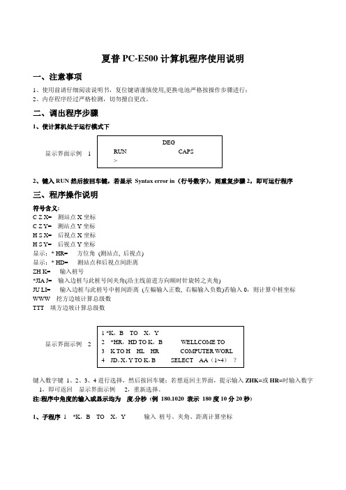
二、调出程序步骤1、使计算机处于运行模式下显示界面示例 12、键入RUN 然后按回车键,若显示 Syntax error in (行号数字),则重复步骤2,即可运行程序三、程序操作说明符号含义:C Z X= 测站点X 坐标C Z Y= 测站点Y 坐标H S X= 后视点X 坐标H S Y= 后视点Y 坐标显示:* HR= 方位角 (测站点, 后视点)显示:* HD= 测站点和后视点间距离ZH K= 输入桩号*JIA J= 输入边桩与此桩号间夹角(沿主线前进方向顺时针旋转之夹角)JU LI= 输入边桩与此桩号中桩间距离 (左幅输入正数, 右幅输入负数)若输入0,则计算中桩坐标 WWW 挖方边坡计算总级数TTT 填方边坡计算总级数显示界面示例 2键入数字键 1、2、3、4进行选择,然后按回车键;若想返回主界面,提示输入ZHK=或HR=时输入数字1,即可返回 显示界面示例 2,重新选择。
注:程序中角度的输入或显示均为 度.分秒 (例 180.1020 表示 180度10分20秒)1、子程序 1 *K ,B TO X ,Y 输入 桩号、夹角、距离计算坐标显示界面示例 4显示界面示例 5输入下一放样桩号、夹角及距离,则重复显示界面示例 5,输入数字1,即可返回 显示界面示例 2,重新选择。
2、子程序 2 *HR ,HD TO K ,B 输入方位角、距离、高差进行设计填挖边桩放样全站仪准备:架设好仪器后,设置方向值,然后退出进入测量中,选则平距即可。
符号含义: FANG YANG OR JIAN CE ?(JC )不用输入,直接按回车键2*HR HD TO K ,B JD= 查出放样段落所属交点号(差直、曲线转角表),输入后按回车键,段落长须跨交点时,不须更改W A FANG JI JI BIAN PO ? 输入放样山头挖方边坡的总级数(横断面查)TIAN FANG JI JI BIAN PO ? 输入放样段落填方边坡的总级数(横断面查)W I= 自路面至原地面(下~上)依次输入挖方边坡坡度(例 1:1.5 则输入 W I=1.5)(横断面查)T I= 自路面至原地面(上~下)依次输入填方边坡坡度(例 1:1.5 则输入 T I=1.5)(横断面查)显示界面示例 7 GAOCH= 测站点高程*YIGAO= 仪器高度(钢卷尺量)以下符号与全站仪“测量”平距界面中符号对应HR= 输入全站仪水平角读数HD= 水平距离VD= 高差显示界面示例 8KAO JIN (YUAN LI ) 只在放样坡口或坡脚时有用,表示测点应靠近或远离中桩此距离后即为坡口或坡脚,即显示为0时表示测点在设计坡面上。
E500 双通道温度监测器用户手册说明书

Trillium US Inc.E500® Dual Channel Temperature MonitorUser’s ManualRev A / November 201597-00032-000For information about Trillium US Inc., visit the Trillium US Inc. Web site at:How to Contact Trillium US Inc. Support:**********************For contact information and a complete listing of Direct Sales, Distributor, and Sales Representative contacts, visit the Trillium US Inc. Web site at:Trillium US Inc. has made its best effort to ensure that the information contained in this document is accurate and reliable. However, the information is subject to change without notice and is provided “AS IS” without warranty of any kind (express or implied). Before placing orders, customers are advised to obtain the latest version of relevant information to verify that information being relied upon is current and complete. All products are sold subject to the terms and conditions of sale supplied at the time of order acknowledgment, including those pertaining to warranty, patent infringement, and limitation of liability. No responsibility is assumed by Trillium US Inc. for the use of this information, including use of this information as the basis for manufacture or sale of any items, nor for infringements of patents or other rights of third parties. This document is the property of Trillium US Inc. and by furnishing this information, Trillium US Inc. grants no license, expressed or implied, under any patents, copyrights, trademarks, trade secrets, or other intellectual property rights of Trillium US Inc. Trillium US Inc., copyright owner of the information contained herein, gives consent for copies to be made of the information only for use within the customer’s organization as related to the use of Trillium US Inc. products. The same consent is given for similar information contained on any Trillium US Inc. Web site or disk used to distribute information to a customer. Trillium US Inc. does give consent to the copying or reproduction by any means of the information contained herein for general distribution, advertising or promotional purposes, or for creating any work for resale. The names of products of Trillium US Inc. or other vendors and suppliers appearing in this document may be trademarks or service marks of their respective owners that may be registered in some jurisdictions. A list of Trillium US Inc. trademarks and service marks can be found at:/Trillium US Inc.1340 Airport Commerce Dr.Bldg. 1 Suite 175Austin, Texas 78741 USATEL. +1 512 441 6893FAX +1 512 443 6665Email: *************************Copyright (©) 2015 by Trillium US Inc., All rights reserved.Copyright (©) 2015 by Trillium US Inc., All rights reserved.Table of Contents1 Revision History (iv)2 Preface (5)2.1 About Trillium US Inc. (5)2.2 Other Services from Trillium US Inc. (5)2.3 About this Manual (5)2.4 Compatibility (6)3 Introduction (6)3.1 E500 Dual Channel Cryogenic Temperature Monitor Features (6)3.2 Description (6)3.2.1 Specifications (6)4 Set Point Relay Pin-out (8)5 Analog Outputs (8)6 E500 User Interface (9)6.1 Diode Curve Selection (9)6.2 Set Point Configuration (9)6.3 Serial Port Interface (12)6.3.1 Serial Port Commands (12)6.4 E500 Curve Programmer (13)7 Ordering Information (14)List of FiguresFigure 1 – E500 Rear Panel (7)Figure 2 – Single Row Mating Connector (1803646) (8)Figure 3 – Channel Set Point Access (10)Figure 4 – Channel Set Point Example (11)Figure 5 – E500 Curve Programmer User Interface (13)List of TablesTable 3-1: E500 Specifications (6)Table 3-2: Rear Panel Features (7)Table 4-1: Set Point Relay Pin-out (8)Table 5-1: E500 Analog Output Pin-Out (8)Table 6-1: Serial Port Pin-Out (12)Table 6-2: Serial Port Settings (12)Table 6-3: Serial Port Commands (12)Table 7-1: E500 Dual Channel Cryogenic Temperature Monitor Ordering Information (14)Table 7-2: E500 Optional Cables (14)1Revision HistoryDate Revision ECR # Description of ChangeJuly 2008 1.0.1 Initial releaseJanuary 2013 1.0.2 Change to update corporate formatFebruary 2013 1.0.3 Corrected Dimensions, Corrected Sensor connection, added weightNovember 2015 A 2821 Rebranding and format changes, removed references to “backlit” LCD DisplayDocument Part Number: 97-00041-0002Preface2.1About Trillium US Inc.Trillium US Inc., a wholly-owned subsidiary of Trillium US Inc., specializes in the manufacture and repair of cryogenic vacuum pumps, cryocoolers (refrigerators) and helium compressors for semiconductor, optical coating, linear accelerators, medical equipment, and R&D applications.You can find just what you need from our range of products and support services:•New Equipment - cryopumps, compressors, cryocoolers, and cryopump controllers.•Comprehensive range of accessories for the installation of whole systems and a complete range of spare parts to repair cryopumps and compressors.2.2Other Services from Trillium US Inc.Trillium US Inc. offers comprehensive refurbishment services for its own equipment as well as for that of most of our competitors. Our products and services are available through our global network of agents and dealers.•Repair and refurbishment services - We offer our own quality products, as well as most other manufactures models, often with off-the-shelf availability.•Exchanges - We offer our own quality products, as well as most makes of cryopumps and helium compressors, which are refurbished and fully warranted.•Technical Support - Our support engineers will help determine if your cryopump system is operating correctly so that you can get your system back to optimum efficiency as soon as possible.o To contact Trillium US Inc. Technical Support:o E-mail: **********************o Telephone: 1-512-441-9258 or Toll Free: 1-800-404-1055•Installation - On-site installation services are available to guarantee performance and save you time.•Training - We offer on-site training to help you and your staff to know more about your cryopump and compressor systems. Our training will give you confidence and the ability to maintain a highest possible uptime for your system.2.3About this ManualThe purpose of this manual is to provide our customers using the E500 Dual Channel Cryogenic Temperature monitor with the information needed to safely and efficiently operate the monitor when operating as part of a cryogenic refrigeration system. Such a system is often comprised of the following equipment:•Cryopump compressors•Coldhead(s) or cryopump(s)•Connecting helium lines•Temperature monitor(s)This manual describes the design, operation and maintenance of the E500 Dual Channel Cryogenic Temperature monitor.2.4CompatibilityThe E500 Dual Channel Cryogenic Temperature Monitor is compatible with most cryopumps and coldheads.3Introduction3.1E500 Dual Channel Cryogenic Temperature Monitor FeaturesThe E500 Dual Channel Cryogenic Temperature Monitor features:•Continuous visual update of two temperature sensors (channels) using an LCD display•Drives two temperature diodes, intended for cryogenic temperature measurement•Diode temperature curve selection from four pre-defined curves•Supports one user-defined, programmable diode curve•Six programmable setpoint relays (three per sensor/channel)•Two 0 – 10 V analog outputs for temperature monitoring (one per sensor/channel)•Provides an RS-232 serial port for a PLC or PC digital interface3.2DescriptionThe E500 Cryogenic Temperature Monitor drives two diode temperature sensors, and provides a visual display of the temperature on an LCD module. Typical applications include monitoring temperature of a two stage coldhead of a cryopump or cryocooler, using one diode (channel) for each stage. It can also be used to monitor two cryopumps or cryocoolers simultaneously, by using one diode (channel) for each coldhead. The high resolution measurement sensors provide noise rejection to deliver precise, accurate temperature readings. The diode curves are user selectable from four (4) pre-defined curves providing support for common diodes. In addition, a user-programmable curve is available for non-supported diodes. Temperature conversion is provided by a 10μA constant current source using a spline interpolation (piecewise polynomial).3.2.1SpecificationsThe E500 specifications are listed in Table 3-1. The E500 rear panel is shown in Figure 1 and described in Table 3-2.Table 3-1: E500 SpecificationsItem SpecificationFeaturesDisplay 2 Temperatures Four Selectable Diode CurvesPower 110/220 VAC Input @ 50/60 Hz(Universal Input)ConnectorsIEC Power Input DB9F (Diode Driver)Dry Contact RatingCarry AC Current 10 A @ 250 VACCarry DC Current 5 A @30 VDC Max Switching Voltage400 VAC300 VDCMax Switching CurrentNO: 10 ANC: 8 AMax Switching PowerNO: 2,500 VANC: 2,000 VA150 WAnalog Output 0 – 10 V, 60mA max Dimensions 6.5” (W) x 7.5” (L) x 3.05” (H) Weight 3.2 lbs.Figure 1 – E500 Rear PanelTable 3-2: Rear Panel FeaturesFeature Description1: IEC Power Entry Universal Power input accepts 110 or 220 VAC at 50 or 60 Hz2: Set Point Relays Dry contacts are provided to trigger external equipment, or to provide status to control electronics, such as a PLC. Three relays are provided for each temperature channel. The top row connector is controlled by Channel #1 sensor, and the bottom is controlled by Channel #2. See Table 4-1 for a detailed pin-out.3: D-Sub 9 Female-Temp Sensors Connect temperature sensor according to the following pin out: •Pin 1: Shield (GND)•Pin 2: No Connect (NC)•Pin 3: NC•Pin 4: Diode Sensor #2 Positive•Pin 5: Diode Sensor #2 Negative•Pin 6 – 7: NC•Pin 8: Diode Sensor #1 Positive•Pin 9: Diode Sensor #1 Negative4: D-Sub 9 Male-RS-232 Serial Port Provides serial interface to a remote serial device. The serial port is intended to be used with a standard “straight through” serial cable (not NULL Modem).•Pin 1: No Connect (NC)•Pin 2: RS-232 Transmit Out•Pin 3: RS-232 Receive In•Pin 4: NC•Pin 5: GND•Pin 6 – 9: NC5: Analog OutputsAnalog outputs are provided for recorder logging, or as status toa PLC. The outputs provide 0 – 10 V for each channel.•Pin 1: Channel #1 Voltage Output•Pin 2: GND•Pin 3: Channel #2 Voltage Output•Pin 4: GND123454Set Point Relay Pin-outTable 4-1 describes the relay configuration. For each channel, 3 separate dry contacts are provided. Each dry contact has three connections: Normally Open, Normally Closed, and Common.Table 4-1: Set Point Relay Pin-outPin-Out(left to right)Top Row Bottom Row Relay PositionPin 1Channel 1 LowRelay Channel 2 LowRelayNormally OpenPin 2 Common Pin 3 Normally ClosedPin 4Channel 1 HighRelay Channel 2 HighRelayNormally OpenPin 5Common Pin 6Normally ClosedPin 7Channel 1 SpareRelay Channel 2 SpareRelayNormally OpenPin 8CommonPin 9Normally ClosedThe dual row connector provided on the E500 requires two male connectors for mating. The recommended mating connector is Phoenix Contact Part Number 1803646, see Figure 2. Note that if only one channel is utilized, only one Phoenix Contact connector is needed.Figure 2 – Single Row Mating Connector (1803646)5Analog OutputsThe E500 provides an analog output for each channel. A terminal block style plug is required to connect to the analog outputs. The recommended mating connector is Phoenix Contact Part Number 1803594. The outputs can provide a maximum output current of 60 mA each. To convert the output voltage to temperature, use the following formula:Temperature (Kelvin) = 35 * Analog Output Voltage (in Volts)This formula provides a maximum range of 0 – 350.0 °K. The pin-out (also shown on the back panel of the unit) is listed in Table 5-1:Table 5-1: E500 Analog Output Pin-OutPin Signal1 Channel #1 Analog Output2 Ground3 Channel #2 Analog Output4 Ground6E500 User InterfaceThe E500 provides a continuous display of the temperature measurements. The display interface also provides diode curve selection, and set point configuration.6.1Diode Curve SelectionThe user can select the diode curve which corresponds to the temperature diode sensor connected to the E500. To select a diode curve:1.Press the MENU button.2.Scroll through the standard diode options by pressing the UP and DOWN buttons.3.When the appropriate diode curve has been selected, press MENU.E500 supports the following standard temperature sensor diodes:•Trillium US Inc. Temperature Diode•CTI Temperature Diode•DT-470 Silicon Diode•DT-670 Silicon Diode6.2Set Point ConfigurationThe user can individually configure each setpoint relay to a unique temperature. Each channel has 3 setpoints associated with its temperature measurement – LOW, HIGH, and SPARE. A flow chart is shown to aid in navigating the menus. In addition, an example is shown at the end of the section. If no buttons are pressed for roughly 10 seconds, the display times out and returns to the main menu. NOTE: the changes are stored and take effect if the menu times out. To configure a setpoint:1.Press the MENU button twice. The first relay is “Channel #1 LO”. When the temperature is below this value, therelay is in the “Active” position. The temperature value is modified by pressing UP or DOWN for each digit. Once the digit has been set, press ENTER to move to the next digit.2.Press the MENU button to configure “Channel #1 HI”. When the temperature is above this value, the relay is inthe “Active” position.3.Press the MENU button to configure “Channel #1 SPARE”. When the temperature is above this value, the relay isin the “Active” position.4.Continue to press the MENU button to cycle through the Channel #2 set points.Figure 3 shows how to access the set points via menu selection. Figure 4 provides an example that will configure Channel #2 Low Set point Relay to 12 K. Begin by pressing MENU to navigate to the “Select Diode” display shown in Figure 4.Figure 4 – Channel Set Point Example6.3Serial Port InterfaceThe E500 provides a DB9 Male connector for serial port communications. A “straight through” serial cable is necessary for interfacing to the serial port. Only pins 2, 3, and 5 are required, see Table 6-1.Table 6-1: Serial Port Pin-OutDB9 Female (to E500) DB9 (to Controller)1 ------------- 12 ------------- 23 ------------- 34 ------------- 45 ------------- 56 ------------- 67 ------------- 78 ------------- 89 ------------- 9All commands start with ‘$’, and end with \r\n. The serial port should be configured as shown in Table 6-2.Table 6-2: Serial Port SettingsBaud Rate 19,200Data Bits 8Parity NONEStop Bits 1Flow Control NONE6.3.1Serial Port CommandsTable 6-3 lists the provided serial port commands.Table 6-3: Serial Port CommandsCommand Returns ExampleGetRev Revision x.x Get Revision SEND: $GetRev\r\n RECEIVE: $Revision 1.0\r\nGetTemp (channel) Channel: 1 or 2xxx.x or“OOR” if outof rangeGet Channel2 TempSEND: $GetTemp 2\r\nRECEIVE: $21.6\r\nGetSetp (channel,relay)Channel: 0 or 1 (0-> Channel 1, 1-> Channel 2) Relay: 0, 1, or 2. 0->LO, 1->HI, 2->SPARE xxx (integer)Get Channel2 SPARE setpointSEND: $GetSetp 1,2\r\nRECEIVE: $280\r\nSetSetp (channel,relay,temp) Channel: 0 or 1 (0-> Channel 1, 1-> Channel 2) Relay: 0, 1, or 2. 0->LO, 1->HI, 2->SPARETemp: xxx (integer, no decimal point)$xxx\r\n(returns thenew valuestored)Set Channel1 LOW setpoint to 12KSEND: $SetSetp 0,0,12\r\nRECEIVE: $12\r\nGetVolt(channel) Channel: 1 or 2 x.xxxxGet Channel2 VoltageSEND: $GetVolt 2\r\nRECEIVE: $1.2345\r\n6.4E500 Curve ProgrammerTo enter data for a user defined diode curve, the E500 Curve Programmer can be used. This utility allows the user to enter the polynomial coefficients that control the voltage to temperature conversion.In order to determine appropriate values, several “Voltage vs. Temperature” data points should be viewed in graph form. The graph can be broken up piece-wise into a maximum of 3 equations. For each of the equations, a trend line should be developed using a program such as Microsoft Excel or Matlab. Up to a 6th order polynomial can be used for each equation to provide maximum flexibility.Once the values have been chosen, the fields shown in Figure 5 should be populated.Figure 5 – E500 Curve Programmer User Interface7Ordering InformationTable 7-1 contains the ordering information for the E500 Dual Channel Cryogenic Temperature Monitor. Customers can also order the optional diode cables listed in Table 7-2.Table 7-1: E500 Dual Channel Cryogenic Temperature Monitor Ordering InformationCryopump Part NumberE500 Dual Channel Cryogenic Temperature Monitor 93-00040-00019” Rack Mount Kit (Fits up to 2 E500s)99-00072-00019” Rack Mount Kit (Fits single E500)99-00072-001 E500 Curve Programmer (to program custom diode curve) 10-00001-000Table 7-2: E500 Optional CablesConfiguration CablesPart Number10 Ft. 15 Ft. 20 Ft. 50 Ft.Single Cryopump or coldheadStandardSingle DiodeCable10133-10 10133-15 10133-20 10133-50Dual Diode Cryopump or coldhead Dual DiodeCable81-00016-010 81-00016-015 81-00016-020 81-00016-050Two Cryopumps or coldheadsDualCryopumpDiode Cable81-00038-010 81-00038-015 81-00038-020 81-00038-050。
三菱变频器 FR-E500 说明书

这样会导致火灾
3. 防止损伤 注 意
各个端子上加的电压只能是使用手册上所规定的电压, 以防止爆裂 确认电缆与正确的端子相连接, 否则, 会发生爆裂 始终应保证正负极性的正确, 以防止爆裂 损坏等等 损坏等等事故 损坏等等
正在通电或断开电源不久, 变频器和制动电阻器处于高温状态, 请不要接触它们, 以免引起烫伤
A-2
4. 其它注意事项
请注意以下事项以防止意外的事故 受伤 触电等:
(1) 搬运和安装
注 意
当搬运产品时, 请使用正确的升降工具以防止损伤 变频器包装箱堆叠层数不要高于限定的以上 确认安装位置和物体能经得起变频器的重量 安装时应按照使用手册的说明 如果变频器被损坏或缺少元件,请不要安装运行 搬运时不要握住前盖板或操作面板,这样会造成脱落 请不要在产品上乘坐或堆放重物 检查变频器安装方向是否正确 防止螺丝 电缆碎片或其它导电物体或油类等可燃性物体进入变频器 变频器是精密仪器 不要使变频器跌落,或受到强烈冲击 请在下述环境下使用 以免引起变频器故障 周围环境温度 -10°C +50°C (不结冰) 90%RH以下 (不凝露) 环 周围环境湿度 -20°C +65°C * 境 储存温度 环境 室内 (无腐蚀性气体,可燃性气体,油雾和尘埃等等) 海拔高度, 振动 海拔1000m以下, 5.9m/s2 以下 (JIS C 0040标准) *在运输时等短时间内可以适用的温度
39
39 39 40 41 41
目 录
3.2.2 3.2.3 3.2.4 3.2.5 3.2.6 3.2.7 3.3 操 3.3.1 3.3.2 3.3.3 3.3.4 3.3.5
按 MODE 键改变监示显示 ................................... 监示 ................................................... 频率设定 ............................................... 参数设定方法............................................ 操作模式 ............................................... 帮助模式 ............................................... 作 ...................................................... 操作前的检查............................................ 外部操作模式(根据外部的频率设定旋钮和外部启动信号的操作) . PU操作模式 用操作面板操作 ............................ 组合操作模式1 (外部启动信号与操作面板并用的操作)......... 组合操作模式2...........................................
PC-E500的使用技巧

PC-E500的使用技巧2687789259由于PC-E500在工程测量中的应用,给测量的内外业工作很大的方便,但由于在说明书中的功能介绍比较笼统,对于初入门者来说,要综合的运用好计算机存在一定的难度。
现在就这些年来在工作中的一些实践经验作一介绍,以供同行借鉴。
着重介绍一下程序的存贮管理和一些语言的运用。
1.现在市场上的计算机在原有的基础上,一般都能扩充到了128KB或者256KB。
这样我们就可以对程序进行分区管理。
具体涉及到的语言有:INIT,DSKF,FILES,KILL,SAVE,LOAD。
1.1 INIT内存空间划分命令格式:INIT“E:**KB将内存划分一部分空间到E盘作为内存区,这样就可以把程序存入内存区,而只在外存区内运行程序。
1.2 DSKF 查磁盘剩余空间命令格式:DSKF“E:***“***” 表示程序名称1.3 FILES显示文件名及属性格式:在RUN状态下直接输入命令FILES,即可显示E盘内的程序名称和程序所占用的内存空间属性。
1.4KILL 删盘文件命令格式:在计算机显示程序属性时,将光标移至要删除的文件位置,输入语句“KILL”即可删除要删除的文件。
1.5 SAVE将程序存入指定设备中(一般外向内调)格式:SAVE“E:***(程序名)在RUN状态下,输入该语句即可将外存区内的程序按输入的名称存入E盘内。
1.6LOAD 调外设程序命令格式:LOAD“E:***(程序名)在RUN状态下,输入该语句即可将E 盘内的指定程序调入外存区,并覆盖以前外存区内的程序,此时便可开始进行计算。
2.与宽行打印机的联机使用2.1在使用中,PC-E500能与一些普通的打印机使用,常用的有EPSON1600针式系列的和CANON-255SP的一些型号的打印机。
如佳能250 。
打印实例:10 OPEN“1200,N,8,1,A,L,&H 1A ,N,N”打开打印机串口20 CONSOLE 80 设每行打印输出80字符(适用于A4纸)2.2 如何打印程序清单1)在RUN状态下,把要打印的程序调入外存区;2) 输入OPEN“1200,N,8,1,A,L,&H 1A ,N,N”打开打印机串口;3) 输入CONSOLE 80 设每行打印输出80字符(适用于A4纸);4) 输入LLIST开始打印。
转载E500消防灭火剂

转载 E 500消防灭火剂000000E-500型泡沫灭火剂属于冷火灭火剂,先进的磁化和鳌合技术在产品工艺中得到应用,先进的纳米技术在生产工艺中得到应用,并创造性地运用了光化学冷火效应灭火。
其独特的灭火机理,A光化学冷火效应;B泡沫覆盖;C水成膜隔离;D聚合层互氧、化学抑制。
灭火过程中使燃烧物质瞬间降温、灭火,绝不复燃。
环保、高效、洁净、无毒无害,还可以吸收烟雾中的有毒气体,并具有卓越的抗高温性能。
是"哈龙淘汰"更新换代的无毒环保、高效灭火的首选消防灭火剂。
E-500优势一、高效:1、快速降温。
E-500灭火实验中,火场温度从1100℃降至人体可触摸温度只需10几秒2、快速渗透。
将水的表面张力72达因/平方厘米降低至17达因/平方厘米,可以快速渗透至燃烧物内部,迅速灭火,并防止复燃3、泡沫生成量大,泡沫细密、稳定,不易破碎,并且流动性好,能够迅速覆盖在燃烧物表面,抑制燃烧并有效防止复燃4、灭火剂及泡沫的溅溢性低,灭火时能有效遏制液体燃烧物的溅溢,避免火势蔓延5、减少火灾用水量二、优异的高效性有助于:1、快速扑灭火势,防止火灾恶化2、减少财物损失3、保护人员安全,利于观察和呼吸,便于消防人员施救和受困人员逃生4、降低灭火支出,减少水渍等破坏通用:5、可以高效扑灭A、B(极性和非极性)、C、D(不与水强反应)四类火灾6、适用于所有的泡沫灭火设施和水系灭火设施,无需改造现有设备7、非常适用于石油、化工、民航、机场、森林、码头及储藏罐区的大型企业和消防队8、罐装灭火器非常适用于住宅、工矿企业、汽车、公共场所等人居生产生活场舍三、优异的通用性有助于:1、节省设备更换的支出2、易于使用,消防部门可直接快速扑灭各种类型火灭3、以植物提取物、食品添加剂和表面活性剂为主要原料4、ODP(臭氧层损耗潜能值)为0.0,不破坏臭氧层5、GWP(温室效应潜能值)为O.0,不影响人类生存环境6、灭火后的生成物在大气及环境中存留寿命(ALT)短,30小时内可完全自行降解四、优异的环保性有助于1、维护可持续发展的生态环境和人居条件,惠及全人类2、促进和谐城市与和谐社会的建设进程3、为一个国家、城市和企业树立负责任的形象4、推动国冢环保政策和可持续发展战略的买施5、生产和使用中不产生任何有毒有害物质6、手、脸等皮肤接触实验中,皮肤无任何不适反应7、漱口实验证明E-500对人体粘膜组织无任何损伤8、无腐蚀性,不损坏储存罐、消防设施及被保护物品9、迅速消除浓烟和有害气体,利于观察和呼吸,方便消防人员施救和火场人员逃生10、灭火后残留物非常易于清理,可自行降解,特别适用于保护石油、化工类产品五、优异的洁净性有助于:1、避免普通灭止剂的毒性对人员健康的潜在危险2、极大降低消防设他的纬护费用3、极大降低扑救后的清理费用4、极大降低灭火剂对保护物品的破坏性F500泡沫液"F-500"灭火功能体现于微胞囊原理。
明基E500商务智能投影机操作手册

智简商务E500投影机功能操作说明目录1.特色功能说明 (3)2.基本设置 (5)2.1遥控器按键说明 (5)2.2 Wifi连接 (5)3.无线投影功能操作说明 (8)3.1 Windows电脑无线投影说明 (8)3.2 苹果Mac电脑无线投影说明 (10)3.3安卓手机/Pad无线投影说明 (10)3.4 iPhone/iPad无线投影说明 (11)4.免PC简报功能操作说明 (12)4.1 内置空间文件读取 (12)4.2 U盘直读 (13)4.3 远程文件调用 (15)5.跨平台文件传输操作说明 (19)5.1 文件上传 (19)5.2 文件下载 (21)6.视频会议系统操作说明 (24)6.1 注册视频会议账号 (24)6.2 召开视频会议 (27)6.3 参加视频会议 (31)7.手机遥控器操作说明 (33)7.1 下载手机遥控器 (33)7.2 手机遥控器操作说明 (34)1.特色功能说明1.1全平台无线投影*不需要连接信号线,局域网下无线投影画面/界面到投影机;*支持Windows系统、iOS系统、安卓手机、安卓Pad、iphone 、iPad*Windows系统下需额外安装Airpin软件,附带光盘或从官网下载;1.2免PC简报*内置WPS及图像处理软件,可以在无PC状况下,简报Word/Excel/PPT/PDF/图片/视频/音频等多种文件;*局域网下,通过IP地址调用指定电脑预设的共享文件,直接打开对应文件简报;*插U盘在投影及USB端口,U盘直读;*内置4.7G储存空间,可通过文件传输功能,局域网内提前将文件传送到投影机内置空间,会议时直接从投影及内部存储空间打开文件;1.3跨平台文件传输*通过投影机IP地址,向投影机内置存储空间,上传或下载文件;*支持Windows系统、iOS系统、安卓手机、安卓Pad、iphone 、iPad 1.4视频会议解决方案:*内置视频会议软件,注册账号后,实现视频会议功能,可主持人控制、屏幕注释、屏幕共享等;*需要参加视频会议的电脑,需安装光盘或从官网下载Zoom软件;需要参加视频会议的手机,需从市场下载Zoom(或叫众目)软件*投影机如果作为视频会议的参与者,建议连接上推荐的外接USB摄像头/麦克风二合一设备1.5手机遥控器:*扫描并下载手机遥控器软件,手机实现遥控器功能,控制智能系统下操作2.基本设置2.1遥控器按键说明菜单/退出:调出投影机菜单选项,在智能系统下操作时,如有投影机菜单,请先按此按键关闭;方向键/OK键:智能系统下上下左右切换,并按OK键进入;返回:智能系统下返回上一层菜单,或退出菜单;智能首页:直接跳转到智能系统的主界面智能菜单:快速调出智能系统的设置菜单2.2 Wifi连接2.2.1 主界面下用遥控器左右切换选择“设置”,点击OK进入;2.2.2选择“网络联机”,进入后选择“无线网络”,找到需连接的无线网络后,用遥控器移动并选择需要的英文字母或数字,输入账号密码;2.2.3网络连接OK后,画面右上角显示如下图标,表示已连接,如出现问号图标,请确认XX密码是否有错误3.无线投影功能操作说明3.1 Windows电脑无线投影说明*投影机连接Wifi无线网络,详细步骤参考2.2说明;*在电脑上安装Airpin软件,软件可在附带光盘中找到,或登录BenQ官网.benq.., 搜索查找E500,在“驱动下载”中找到“Airpin投屏PC端驱动”,下载并安装;*笔记本连接到投影机同一个无线路由器或局域网下;*桌面上找到如下图标,双击运行;*右下角程序栏中,右键选择如下图标;*在出现的界面下选择“屏幕镜像到”,并在右侧扩展选项中选择“ATV*****”,可以将笔记本桌面整体投影到投影机上,笔记本上的操作可实时在投影机上显示;如选择“推送媒体到”,并在右侧扩展选项中选择“ATV*****”,可以将笔记本电脑指定的媒体播放界面,投影到投影机上显示;而不是整个桌面;3.2 苹果Mac电脑无线投影说明*投影机连接Wifi无线网络,详细步骤参考2.2说明;*笔记本连接到投影机同一个无线路由器或局域网下;*在笔记本右上角图标中找到Airplay图标,在出现的下拉菜单中选择“ATV*****”,可以将笔记本桌面整体投影到投影机上,笔记本上的操作可实时在投影机上显示;如选择“Specific App ”,可将指定软件的界面投影到投影机上显示;3.3安卓手机/Pad无线投影说明*投影机连接Wifi无线网络,详细步骤参考2.2说明;*手机或Pad连接到投影机同一个无线路由器或局域网下;*在手机/Pad“设置”中的“显示”中,找到“无线显示”或“投射屏幕”;不同品牌的名称可能不一样;*搜索设备,选择“ATV*****”,可以将手机桌面整体投影到投影机上,3.4 iPhone/iPad无线投影说明*投影机连接Wifi无线网络,详细步骤参考2.2说明;*手机或Pad连接到投影机同一个无线路由器或局域网下;*从手机屏幕底部向上滑动,点击打开Airplay;*开启“镜像”功能,在出现的设备清单中选择“ATV*****”,可以将手机桌面整体投影到投影机上;4.免PC简报功能操作说明4.1内置空间文件读取*主界面下用遥控器左右键,选择“文件管理器”,并按OK键进入下一界面;*选择“本机读取”,并按OK键进入下一界面;*选择本机,并按OK键进入下一界面;*选择需打开的Word/Excel/PPT/PDF/图片/视频/音频等多种格式文件;选择推荐的打开程序,打开文件;4.2 U盘直读*方法一:U盘查到投影机后侧USB 接口,在弹出的提示框中选择“所有文件“,选择对应磁盘,并找到需打开的Word/Excel/PPT/PDF/图片/视频/音频等多种格式文件;选择推荐的打开程序,打开文件;*方法二:遥控器方向键向左,调出如下界面,选择“USB“,进入下一界面,选择对应磁盘,并找到需打开的Word/Excel/PPT/PDF/图片/视频/音频等多种格式文件;选择推荐的打开程序,打开文件;方法三:主界面下用遥控器左右键,选择“文件管理器”,继续选择“本机读取”,选择对应磁盘,并找到需打开的Word/Excel/PPT/PDF/图片/视频/音频等多种格式文件;选择推荐的打开程序,打开文件;4.3 远程文件调用*投影机连接Wifi无线网络,详细步骤参考2.2说明;*计划远程调用的笔记本连接到投影机同一个无线路由器或局域网下;*计划远程调用的笔记本设置好共享;*投影机主界面下用遥控器左右键,选择“文件管理器”,并按OK键进入下一界面;*选择“远端读取”,并按OK键进入下一界面;*选择“手工添加“,并在弹出的界面的”设备地址“,输入同局域网内,需读取的设备的IP地址;如果目标设备已设登陆密码,在此过程中,对应需输入;*出现目标设备IP命名的图标后,选中进入,可看到目标设备(电脑)已预设好的共享文件夹;*找到需打开的Word/Excel/PPT/PDF/图片/视频/音频等多种格式文件;选择推荐的打开程序,打开文件;5.跨平台文件传输操作说明5.1文件上传*投影机连接Wifi无线网络,详细步骤参考2.2说明;*笔记本/手机/Pad连接到投影机同一个无线路由器或局域网下;*投影机主界面下用遥控器左右键,选择“文件管理器”,并按OK键进入下一界面;*选择“文件传输”,并按OK键进入下一界面;*在界面中可看到“请在电脑/手机浏览器输入以下地址:10.89.8.195:56790“,其中10.89.8.195为投影机当前IP地址, 根据网络不同会有变化,不固定;*在电脑/手机/Pad的浏览器地址栏中,输入10.89.8.195:56790, 请注意必须加上“Http://”*点击“上传文件“, 并选择需要传输到投影机的文件,传输完成后投影机界面下会显示上传文件;*选中“打开”,并按下OK,可打开已上传的文件,譬如Word/Excel/PPT/PDF/图片/视频/音频等多种格式文件;*选中“删除”,并按下OK,可删除对应的文件;5.2 文件下载*投影机连接Wifi无线网络,详细步骤参考2.2说明;*笔记本/手机/Pad连接到投影机同一个无线路由器或局域网下;*投影机主界面下用遥控器左右键,选择“文件管理器”,并按OK键进入下一界面;*选择“本机读取”,并按OK键进入下一界面;*需共享的内置空间,或外接磁盘(U盘等),选中“共享磁盘”,按下OK键;*在新出现的界面中,选中“启动服务”,此时将出现ftp:// 10.89.8.195:2121, 其中10.89.8.195为投影机当前的IP地址,(下图为示意,IP地址有变化)。
- 1、下载文档前请自行甄别文档内容的完整性,平台不提供额外的编辑、内容补充、找答案等附加服务。
- 2、"仅部分预览"的文档,不可在线预览部分如存在完整性等问题,可反馈申请退款(可完整预览的文档不适用该条件!)。
- 3、如文档侵犯您的权益,请联系客服反馈,我们会尽快为您处理(人工客服工作时间:9:00-18:30)。
新品E500培训教材
——3D魔界手机
培训教材核心要领:体验外观、体验界面、学会“操作,通过体验找感觉!
第一部分:引言
可以说E500是一款目前市面上鲜有的真正魔方3D菜单操作界面手机,所以本教材以“讲解为辅,演示为主”的介绍方式,视频、相册、音乐演示内容会制定统一文件供终端下载使用。
让顾客通过体验产品设计时尚、功能强大而喜欢上它,从而促成销售。
产品本身功能很强大,为了达到上述效果便于大家记忆,本教材特采用了“一三四产品销售法”——即“一句话开场,三个不一样,每个不一样有四个核心点”!
第二部分——一句话开场
演示动作:1、点击屏幕下方正中间的触摸键进入3D魔方界面;2、用食指轻轻在屏幕上由左至右或者由右至左滑动可以看到不同的3D魔方界面(联系人、工具、快捷方式、多媒体);3、只要用手指轻轻一点击其中的任意一个3D魔方界面就可以进入相应的专题菜单界面进行操作
销售话术:
你好,看看这款万利达新推出的3D魔界手机,它的3D魔界菜单绝对是全场手机中独一无二的! 其他手机有的功能它都有,还有三大功能和其他手机不一样哦!
小结:(向顾客推荐E500时促销员一定要用绝对自信的眼神和语气与顾客交流,言语中要透露出一股对E500性能优越的自豪感,说到“三点和其他手机不一样”时语气带有一些神秘感,勾起顾客了解兴趣。
)
第三部分——三个不一样
一、操作界面不一样
1.E500共有3种菜单界面:A、3D魔方菜单界面 B、4种专题菜单界面C、32宫格时尚菜单两种显示
演示动作:
A、如何进入3D魔方菜单界面?当手机在待机状态或者一级菜单的状态下点击屏幕下方正中间的触摸键即
可进入,如图1:
点击正中间的触摸键图1
B、如何进入4种专题菜单界面?进入3D魔方菜单界面后,点击其中任意一个魔方菜单即可进入(联系人、
工具、快捷方式、多媒体)如图2:图2多媒体
3D
C 、如何进如32宫格时尚菜单?进入4种专题菜单界面后,点击屏幕最右下方的图标即可进入,进入后您看到的将是16宫格的菜单显示,有两种方式可以实现32宫格菜单显示:第一、左右滑动每行的图标,即
可拉出隐藏的图标,按住一项快捷菜单3秒后还可左右调整菜单位置;第二、将手机横过来成90度垂直
也可实现。
如图3:
图3
销售话术: 这款手机采用了时下最尖端的3D 魔幻菜单,您看看是不是比电脑操作界面还要酷!
小结:演示这项功能时,手指滑动界面的速度要适中,把3D 魔方菜单各项菜单和16宫格快捷菜单位置调整演示给顾客看,同时配合自信的销售话术,把顾客的注意力吸引到手机界面上来,让顾客对手机产生兴趣.
2. 专辑音乐界面:可以设置10个喜欢的音乐专辑,惯性滑选进入专辑点歌。
演示动作:进入音乐播放菜单 → 横向放置手机进入音乐专辑界面 → 选择“演示专辑” → 向顾客演示E500演示专辑内的音乐.
销售话术: 设置音乐专辑将喜欢的音乐分类,再也不用到费力寻找自己想听的音乐,用手指轻轻一滑或是拿住手机轻轻一甩还能换歌!
小结:演示机上柜前在机身或者机身内存卡内保存好E500音乐专辑(各项)演示内容,E500适合演示弦乐类音乐,不太适合演示电子音类混音歌曲;由于E500机身薄,导致E500机身喇叭外放声音不是特别大,尽量推
荐顾客用耳机体验音乐效果.演示歌曲的同时询问顾客”怎么样?音质很棒吧?!”
3.动感指滑相册:手机支持浏览大型高清照片,指滑调整照片大小、选定照片位置及变换照片.
演示动作:进入“相册”→点击照片进行“查看”→演示滑动变换照片,从左/右下角向右/左上角滑动放大照片,反方向缩小照片.并且还照片还可以左右滑动进行上一张下一张的选择!
销售话术:这是市面上唯一一款能在手机上浏览数码相机拍摄照片的魔界手机,您看看这照片多清晰,还可以随心所欲的通过滑动屏幕放大、缩小、变换照片,比数码相机还好用.
小结:E500可以播放1.7M以下的数码照片,是同类手机不能做到的.演示手机前在手机内预存好大小合适,画面漂亮的数码照片,然后进入相册,放大照片向顾客演示E500的强大显示功能,边演示边结合销售话术进行讲解.
4.大头贴电话薄:10条亲密联系人大头贴电话薄循环滚动菜单,让亲密好友更亲密。
演示动作:进入“联系人”菜单→滑动联系人菜单向顾客演示→点击联系人向顾客展示快捷通话、写短信功能。
销售话术:拖动大头贴选择和最亲密的好友面对面,轻轻一按就能和他们通话或是短信聊天,您看,就这么方便.
小结:介绍这项功能时要突出”亲密朋友”的元素,语言亲切,让顾客能觉得仿佛看到这个界面就真的见到了自己最好的朋友一样.
二、硬件材质不一样
1、世界顶尖技术的3.2寸超高清显示屏,提供前所未有的视觉盛宴
演示动作:进入“视频”选项播放E500统一演示视频(江若琳-你不在了)
销售话术:这款E500采用的是世界顶尖的高清屏,屏幕成像效果非常细腻,而且色彩鲜艳,对比度高,播放高清视频无拖影,您看,连歌词都能清楚的显示在屏幕下方,能观看这样清晰的视频是普通的手机是绝对没法做到的.
小结:演示E500高清屏时使用统一演示视频,边向顾客演示视频,边提醒顾客留意视频下方的字幕!
2、高清摄像头,媲美数码相机:智能旋转触控设置菜单,实值200万像素高清原装进口摄像头,相机反应速度快,屏幕成像无拖影,夜间灯光拍效果下拍摄效果极佳.
演示动作:进入32宫格菜单→进入”照相机”功能向客户演示高清成像效果并拍照演示→打开相机”功能设置”菜单旋转调试功能
E500实景展示1E500实景展示2半透明设置菜单
销售话术:这款手机采用了原装进口的高清摄像头,像素实值200万,拍照效果比一般手机300万像素效果
好很多,而且夜间灯光下一样拍照清晰,性能堪比数码相机.
小结:由于E500拍照性能卓越,拍照时注意取景色彩鲜明、对比度高的景色就可以获得另客户满意的照片了.在高像素模式下拍照,按下快门后镜头停顿一秒钟,让照相机成像.
3、高性能处理器:E500采用了超大1G运行内存,CPU性能优越,手机反应特别快,同时采用EDGE上网技
术.
演示动作:登陆UCWEB浏览网络
销售话术:这款E500采用了成本昂贵的高速CPU和1G超大运行内存,并且采用了EDGE上网技术,配合强大
的处理器让咱们的E500上网超快,就象在电脑上上网一样!
小结: 由于上网的演示需要SIM卡支持,所以各位促销员最好能将自己的卡放置在样机内做网络演示.
4、金属锌合金机身设计:E500机身采用耐腐蚀的锌合金镶边,整机设计一气呵成,个性鲜明.
演示动作:双手持机递给顾客.
销售话术:这款手机机身采用不会生锈的锌合金设计,与屏幕无缝结合,整部手机造型一气呵成,个性鲜明
而且非常有质感,来,您感觉一下……
小结:将手机递给顾客的同时跟客户说“来,您感觉一下”,表情和语气诚恳.
三、手机功能不一样
1、急速纯平手写、带力反馈触屏: E500的屏幕反应速度肯定是全场最快的一款,无论是手写短信还是选择
菜单,都能给您飞快的享受,并且手机还带力反馈功能,让您使用起来更得心应手,您试试,肯定会给您带来
惊喜!
2、高精度语音识别功能:识别准确,反映迅速.本来语音识别功能就是想给人方便节省时间,如果误操作
太多就会浪费您宝贵的时间。
现在市面上大多数有语音识别功能的手机语音识别率都不高,这款手机它的
语音识别率能达到百分之98基本不会出现误操作的情况让您操作起来非常的方便。
注:进入快捷菜单界面,点击语音识别快速准确下达指令当面给顾客演示。
操作完之后立即以非常自信的眼神和语气看着顾客然后接上一句“您看识别相当准确反映也很迅速吧”
3、个性时间调节方式:E500的设计可谓是人性化与个性化的完美结合,就连时间日期的调节方式也那么酷!他无需像传统的手机一样去设置时间,你只要手机上下滑动即可完成,非常炫酷!
4.强大的附加功能:支持手机股票软件下载、MSN、飞信、QQ、文曲星、JAVA、蓝牙、收音机……
基本参数
网络 GSM/GPRS/EDGE
屏幕 3.2英寸 WQVGA 240×400
电池容量 1000mAh
信息短信息·1000条
MMS彩信△·100条
E-mail△·POP3
名片式电话本·1000组
功能应用摄像头·200万像素
音频播放·
视频播放·MP4 3GP
电子书·
FM收音机·
T-Flash内存扩展·支持8GB
蓝牙2.0 ·
USB2.0 ·
手写输入·
闹钟·
日程表/备忘录·
秒表·
计算器·
电子词典·
单位转换器·
世界时钟·
精彩游戏·
标准配置标准电池 2
标准充电器 1
立体声耳机 1
数据线/CD 1
随机光盘 1
万利达品牌推广部
2009年11月30日。