熔断器产品说明书
欧标EN60598-2-22适用环境内外用熔断器说明书
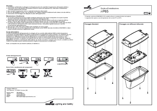
• Prodotto conforme EN60598-2-22 e adatto all’uso in ambienti interni ed esterni.• L’apparecchio opera a una temperatura che va dai 5o C ai 25o C.Fissaggio Standard Fissaggio con diffusore bifaccialeSicurezza1. Controllare sull’etichetta il voltaggio e la frequenza prima di connettere l’apparecchio all’impianto elettrico.2. Assicurarsi che la rete elettrica sia assente mentre si lavora sull’apparecchio, nella fase di installazione o durante qualsiasi altro servizio.3. Non montare l’apparecchio vicino a materiali facilmente infiammabili.4. Per non danneggiare il driver, non combinare con i ballast magnetici tradizionali sullo stesso circuito elettrico.5. Assicurarsi che il fissaggio sia adeguato al peso dell’apparecchio.Manutenzione e Smaltimento1. Al momento dell’autorizzazione e della consegna assicurarsi che venga consegnata una copia di queste istruzioni all’autorità responsabile della manutenzione dell’apparecchio.2. Determinati servizi (ad esempio la pulizia dell’apparecchio) devono essere svolti solo a impianto elettrico spento. Prima di ogni intervento su di esse controllare sempre che non ci sia passaggio di corrente.3. La pulizia deve essere svolta regolarmente per evitare che la sporcizia si accumuli ad un livello tale da influiresulle prestazioni dell’apparecchio o sulla sicurezza termica. Una pulizia regolare assicura il corretto funzionamento dell’apparecchio.4. Non toccare i LED. Per pulire soffiare sulla superficie con aria o azoto.5. Alla fine del suo ciclo di vita l’apparecchio è classificato come WEEE secondo le direttive 2002/96/EC e deveessere smaltito secondo la legislazione locale.Durata della batteriaIl livello di prestazione dell’apparecchio è collegato all’uso corretto della batteria NiMH ad alta temperatura.La durata di vita della batteria può essere compromessa se l’apparecchio viene montato in un ambiente con una temperatura maggiore di 25°C. Tenere l’apparecchio in un ambiente con temperatura che va tra 0°C e 25°C. Sostituire con una batteria Ni-Mh ad alte temperature in base al codice articolo fornito dal produttore. Nondanneggiare la guaina. La batteria va sostituita solo nel caso in cui la durata nominale non venga più raggiunta.Attenzione: Durante lo smaltimento della batteria non forarla, bruciarla o causare corto circuiti. La batteria contiene Cadmio e dovrebbe essere smaltita secondo le regole di sicurezza per lo smaltimento.Nota: La lampada non può essere sostituita, le batterie sì.Pulizia dell’apparecchioEnd of Life e smaltimento dei componentiAssemblaggioFissaggio pittogrammi (a richiesta - non in dotazione)。
电气熔断器说明书
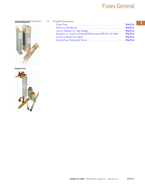
V14-T1-1Fuses GeneralCurrent Limiting FusesExpulsion Fuses1.1Product OverviewPower Fuse . . . . . . . . . . . . . . . . . . . . . . . . . . . . . . . . . . . . . . . . . . . . .V14-T1-2Power vs. Distribution . . . . . . . . . . . . . . . . . . . . . . . . . . . . . . . . . . . . .V14-T1-2Low vs. Medium vs. High Voltage . . . . . . . . . . . . . . . . . . . . . . . . . . . .V14-T1-2Expulsion vs. Current Limiting (Definitions per ANSI C47.40-1993). . .V14-T1-3Current Limiting Fuse Types. . . . . . . . . . . . . . . . . . . . . . . . . . . . . . . . .V14-T1-3General Fuse Component Terms . . . . . . . . . . . . . . . . . . . . . . . . . . . . .V14-T1-31.1Fuses GeneralProduct OverviewTypical Eaton FusesContentsDescription PageCurrent Limiting Fuse Types . . . . . . . . . . . . . . . . .V14-T1-3Expulsion vs. Current Limiting(Definitions per ANSI C47.40-1993). . . . . . . . . . .V14-T1-3General Fuse Component Terms. . . . . . . . . . . . . .V14-T1-3Product OverviewPower FuseEaton’s roots in themedium voltage powerfuse business beganover 75 years ago underWestinghouse® Electric.In 1935, Westinghouseintroduced the mediumvoltage boric acid expulsionfuse followed by the mediumvoltage current limiting fuse.Even today, medium voltagefuses continue to use thatcore technology. Eatoncontinues to build onthe technology legacyby engineering highperformance, cost-effectivepower fuse products.Eaton’s medium voltagefuses are manufactured andtested to the requirementsof the C37-4X series ofstandards that are maintainedand updated regularly tomaintain currency withindustry practices. Thesestandards are:IEEE Std. C37.40™IEEE Standard ServiceConditions and Definitionsfor High Voltage Fuses,Distribution Enclosed Single-Pole Air Switches, FuseDisconnecting Switches,and Accessories (ANSI).IEEE Std. C37.41™IEEE Standard DesignTests for High-Voltage(>1000V) Fuses, Fuse andDisconnecting Cutouts,Distribution Enclosed Single-Pole Air Switches, FuseDisconnecting Switches, andFuse Links and Accessoriesused with These Devices(ANSI).IEEE Std. C37.42™IEEE Standard Specificationsfor High-Voltage (>1000V)Expulsion-Type Distribution-Class Fuses, Fuse andDisconnecting Cutouts,Fuse DisconnectingSwitches, and Fuse Links,and Accessories used withThese Devices (ANSI).IEEE Std. C37.46™IEEE Standard Specificationsfor High Voltage Expulsionand Current Limiting TypePower Class Fuses and FuseDisconnecting Switches.IEEE Std. C37.47™IEEE Standard Specificationsfor High Voltage CurrentLimiting Type DistributionClass Fuses and FuseDisconnecting Switches.The following IEEE standardsare also applicable to the fuseproducts covered in thispublication:IEEE Std. C37.48™IEEE Guide for theApplication, Operation, andMaintenance of High VoltageFuses, Distribution EnclosedSingle-Pole Air Switches,Fuse DisconnectingSwitches, and Accessories(ANSI).IEEE Std. C37.48.1™IEEE Guide for theClassification, Application,and Coordination of Current-Limiting Fuses with RatedVoltages 1–38 kV.A better understanding ofsome fuse terminology willhelp you understand andselect the correct fuse. Thefollowing is a brief overviewof those terms.Power vs. DistributionThe differentiation is intendedto indicate the test conditionsand where fuses are normallyapplied on an electricalsystem, based on specificrequirements for generatingsources, substations anddistribution lines. Eachclass has its own uniqueset of voltage, current andconstruction requirements(see C37.42, .46 and .47).Low vs. Medium vs.High VoltageWhile fuses are defined inthe ANSI standards as eitherlow or high voltage, Eatonhas elected to name theirfuses to correspond with theequipment in which they areinstalled. Therefore, per ANSIC84, our fuses are namedas follows:●Low voltage—1000V andbelow●Medium voltage—greaterthan 1000 to 69,000V●High voltage—greater than69,000VV14-T1-2V14-T1-31.1Fuses GeneralProduct OverviewExpulsion vs. CurrentLimiting (Definitions per ANSI C47.40-1993)An expulsion fuse is a vented fuse in which the expulsion effect of the gases produced by internal arcing, either alone or aided by other mechanisms, results in current interruption.A current limiting fuse is a fuse that, when its current responsive element is melted by a current within the fuse’s specified current limiting range, abruptly introduces a high resistance to reduce current magnitude and duration, resulting in subsequent currentinterruption. Refer to Fuse Types Protection Range figure below for a features comparison.An expulsion fuse is not current limiting and as aresult limits the duration of a fault on the electrical system, not the magnitude.Current Limiting Fuse TypesThere are three current limiting fuse types: Backup, General Purpose and Full Range. It is important that the user have an understanding of these definitions to ensure proper application of the fuse (see Fuse Types Protection Range figure below).Backup FusesA fuse capable of interrupting all currents from themaximum rated interrupting current down to the rated minimum interrupting current.Backup fuses are always used in a series with another interrupting device capable of interrupting currents below the fuse’s minimum interrupting current.General Purpose FusesA fuse capable of interrupting all currents from the rated interrupting current down to the current that causes melting of the fusible element in no less than one hour.General Purpose fuses are typically used to protect feeders and components such as transformers.Full Range FusesA fuse capable of interrupting all currents from the rated interrupting current down to the minimum continuous current that causes melting of the fusible element, with the fuse applied at the maximum ambient temperature specified by the manufacturer.General High Voltage Fuse ComparisonFuse Types Protection RangeExpulsion Current Limiting VentedSealed Electromechanical StaticInterrupts at current zeroLimits fault currentGenerally higher voltage and current application capabilitiesGenerally higher interrupting ratings Different time/current characteristicsDifferent time/current characteristicsC u r r e n t L i m i t i n g T y p eInterrupting Currenti i hr.i min.i max.i max. — Maximum rated interrupting current i min. — Minimum rated interrupting currenti hr. — Current causing element melting in 1 houri — Any current melting element with no time limitGeneral Fuse Component TermsFuse Refill Unit (of an Expulsion Fuse)A fuse refill unit is a replaceable assembly containing the calibrated current-responsive fuse element and certain other items that facilitate current interruption. On its own, the refill unit has no interrupting ability. A refill unit must be mounted in a fuse holder with a spring assembly to form a refillable fuse unit. The refill unit is the section of the fuse that must be replaced after a fuse operation.Fuse Holder (of an Expulsion Fuse)A fuse holder is a reusable holder that when equipped with a fuse refill unit forms a fuse unit, capable of interrupting an overload or fault current. A fuse holder is supplied with a spring and shunt assembly, necessary to complete the internal interrupting assembly. The spring and shunt assembly is supplied with the fuse holder but is also available as a replacement part, as it may need replacement after several of heavy operations.Fuse UnitA fuse unit is a replaceable unit or assembly that isable, on its own, to perform current interruption. Inthe case of a refillable fuse unit, the refill unit must be replaced after a fuseoperation. Where a complete fuse unit is supplied from the factory, the complete fuse unit must be replaced after a fuse operation. All current-limiting fuses are fuse units.Exhaust Control DeviceWhen expulsion fuses are used in enclosures, exhaust control devices (filters,condensers or mufflers) are used to control the sound of the fuse operation, and to de-ionize and absorb the fuse exhaust products. These devices are normally supplied separately, because ofdifferent characteristics and ratings. They are reusable but may need replacement after several heavy operations.MountingA mounting provides all the necessary parts to safely mount a fuse in its intended piece of equipment. The base is the metal support to which all other pieces attach. Insulators attach to the base and insulate the live fuse unit from the base and everything beyond the base. Live parts are the parts of the mounting that are energized onceelectricity is flowing. The live parts provide the means to hold the fuse unit in place, electrical contact, and a place to make line and load connections.Non-Disconnect Mounting A non-disconnect mounting does not provide a means for removing the fuse unit until the circuit is dead and the fuse unit can be removed manually. The fuse unit is held in place by friction through the use of fuse clips or by a cross bar.1.1Fuses GeneralProduct OverviewDisconnect MountingThe disconnect mountingallows the fuse unit to beremoved (off load) using aninsulated switch stick. Theswitch stick grabs a pull ringand disconnects the fuse unitthat may then be lifted out ofits mounting.Dropout MountingDropout mountings areused in outdoor applications.The fuse unit is equippedwith a mechanical trigger thatunlatches the upper contact,allowing the fuse unit to dropout, increasing the dielectricseparation, and providingvisible indication of ablown fuse.Live PartsLive parts were brieflydiscussed as part of the“Mounting” definition.Everything above theinsulators on the mountingexcluding the fuse unit, fuseholder, and the fuse endfittings (if required) areconsidered the live parts. Fuseend fittings are discussednext and are not requiredwith non-disconnect liveparts, but are required andincluded with disconnect liveparts. Live parts may be soldseparately as replacementparts or for new OEMapplications.End FittingsEnd fittings are metal partsthat attach to each end of afuse unit’s ferrules (end caps).As previously mentioned,they are used solely withdisconnect fuse applicationsor when converting a non-disconnect to a disconnectfuse configuration.When end fittings areordered, a fitting for each endof the fuse is included. Keepin mind that end fittings canbecome damaged in use and,therefore, are sold separatelyfrom the live parts whennecessary. It is not necessaryto purchase an entire set oflive parts when only the endfittings are required.V14-T1-4。
NH 熔断器选型手册说明书

NH熔断器选型手册NH- Low voltage H.R.C Fuse西安开尔泰电力电子制造有限公司Xian Kaiert Power Electronics Manufactoring Co.,Ltd.目录TABLE OF CONTENT页码PAGE NH熔断器介绍 3AC NH-400V gG-gL 4-5 AC NH-500V gG-gL 5-7 ACNH-690V gG-gL 7-8 AC NH-500V aM 9AC NH-690V aM 9-10 NH熔断器外形尺寸图10-11 NH熔断器底座外形尺寸图12-14 NH熔断器隔离开关15-19NH 系列低压高分断能力熔断器介绍Product Introduction● 额定电压:400Vac ,500Vac ,690 ac ,1200 Vac ● 额定电流:4A ~1600A ● 七种规格外形尺寸 ● 高分断能力 ● 视觉指示器● 符合GB13539国家低压熔断器标准● 符合IEC60269国际电工低压熔断器标准 ● 符合VDE0636标准第1部分● 符合DIN43620标准第1部分-第4部分NH 高分断低压熔断器按照下列尺寸、电流额定值及运行等级生产:Size 000 2A ~100A Size 00 125A ~160A Size 0 6A ~160A Size 1 80A ~250A Size 2 125A ~400A Size 3250A ~800ASize 4 630A ~1600A Size 4a800A ~1600A本公司生产的NH 系列低压高分断能力熔断器(以下简称NH 熔断器)在吸收国内外同行的产品特点的基础上,在制造工艺、加工设备、检验手段等进行了改进提高,产品性能指标全面符合国际电工委员会标准IEC60269和国家标准GB13539低压熔断器标准。
在国内同行业居领先水平。
本公司生产的NH 熔断器已经广泛用于通讯、电站、开关柜、石油化工、风力发电等行业,获得了用户的一致好评。
PTS120660V010 PTC熔断器数据手册说明书

4397Product features• Positive Temperature Coefficient (PTC)• SMT resettable fuse • Low resistance • Fast time-to-trip• Voltage range 6 V to 60 V • Current range from 0.05A to 2.0A • 1206 (3216 metric) compact footprint •Moisture sensitivity level (MSL): 1Applications• USB peripherals•Plug and play protection for motherboards and peripherals • Power tools• Battery and port protection for mobile/smart phones • Game console port protection • Set-top-boxes•Tablets, notebooks, netbooks, laptops and desktops• Rechargeable battery packs •Digital cameras• Appliances and white goods •Consumer electronicsAgency information• cURus Recognition file number: E343021•TUV: R50192872PTS1206SMD PTC fusesPb HALOGENHF FREEEnvironmental compliancePart number/orderingPTS120660V010• PT= PTC fuse • S= Surface mount • 1206= size code•60V= Maximium dc voltage rating •010= Ihold rating (010=0.10 A2Technical Data 4397Effective November 2021PTS1206SMD PTC fuses/electronicsProduct specificationsVmax 1lmax 2lhold 3ltrip 4Pd 5Time to trip (maximum)Resistance Agency informationPart Number7(V dc )(A)(A)(A)typical (W)(A)(seconds)Initial (R i )minimum (Ω)1maximum (Ω)PartmarkingcURus TUVPTS120660V005601000.050.150.40.25 1.5 3.650TH x x PTS120660V010601000.100.250.40.5 1.0 1.615TY x x PTS120630V012301000.120.290.510.2 1.46TJ x x PTS120630V016301000.160.370.510.3 1.1 4.5TK x x PTS120624V020241000.200.420.680.10.65 2.6TL x x PTS120616V025161000.250.500.680.080.55 2.3TN x x PTS120616V035161000.350.750.680.10.25 1.2TP x x PTS12066V05061000.50 1.00.680.10.150.7TQ x x PTS120615V050151000.50 1.00.680.10.150.7TQ1x x PTS12066V07561000.75 1.50.680.10.090.29TR x x PTS12066V1006100 1.0 1.80.880.30.060.21TS x x PTS12066V1106100 1.1 2.20.880.10.070.2TU x x PTS12066V1506100 1.5 3.00.880.30.040.12TV x x PTS12066V20061002.03.51.081.50.020.08TXxxRecommended pad layout–mmDimensions–mm 1. Vmax: Maximum continuous voltage the device can withstand without damage at current 2. Imax: Maximum fault current the device can withstand without damage at rated voltage 3. Ihold: Maximum current the device will pass without interruption at +23 °C still air4.Itrip: Minimum current that will transition the device from low resistance to high resistance at +23 °C still air5. Pd: Power dissipated from the device when in tripped state at +23 °C still air6. R i : Minimum resistance of the device at +23 °CR 1: Maximum resistance of the device when measured one hour post reflow at +23 °C 7. Part Number Definition: PTS1206xVxxx PTS1206 = Product code and size xV = Voltage rating (Vmax) xxx = Ampere rating (Ihold)Part numberAminimum Amaximum Bminimum Bmaximum Cminimum Cmaximum Dminimum Dmaximum Eminimum EmaximumF G HPTS120660V005 3.00 3.50 1.50 1.800.500.900.1800.500.100.45 2.0 1.0 1.9PTS120660V010 3.00 3.50 1.50 1.800.500.900.1800.500.100.45 2.0 1.0 1.9PTS120630V012 3.00 3.50 1.50 1.800.350.680.1800.500.100.45 2.0 1.0 1.9PTS120630V016 3.00 3.50 1.50 1.800.280.680.1800.500.100.45 2.0 1.0 1.9PTS120624V020 3.00 3.50 1.50 1.800.280.680.1800.500.100.45 2.0 1.0 1.9PTS120616V025 3.00 3.50 1.50 1.800.280.680.1800.500.100.45 2.0 1.0 1.9PTS120616V035 3.00 3.50 1.50 1.800.280.680.1800.500.100.45 2.0 1.0 1.9PTS12066V050 3.00 3.50 1.50 1.800.280.680.1800.500.100.45 2.0 1.0 1.9PTS120615V050 3.00 3.50 1.50 1.800.28 1.060.1800.500.100.45 2.0 1.0 1.9PTS12066V075 3.00 3.50 1.50 1.800.280.680.1800.500.100.45 2.0 1.0 1.93Technical Data 4397Effective November 2021PTS1206SMD PTC fuses /electronicsTime to trip curves at +23ºCT emperature derating curve4Technical Data 4397Effective November 2021PTS1206SMD PTC fuses/electronicsGeneral specificationsOperating temperature: -40 °C to + 85 °C (with derating)Storage temperature: -10 °C to + 40 °C Storage relative humidity: 75%Storage conditon: Keep away form corrosive atmosphere and sunlight Storage duration: 1 yearThermal shock: (20 cycles - 40 °C to + 85 °C) -33% typical resistance change Humidity: +85 °C, 85% relative humidity, 1000 hours ±5% typical resistance change Resistance to solvents: MIL-STD- 202 Method 215Packaging information-mmSupplied in tape and reel packaging, 5000 parts per 7.0” diameter reel (EIA-481 compliant)PTS120630V012, PTS120630V016, PTS120624V020, PTS120616V025, PTS120616V035, PTS12066V050, PTS12066V075, PTS120660V005,PTS120660V010, PTS12066V100, PTS12066V110Section A–AUser Direction of FeedEatonElectronics Division 1000 Eaton Boulevard Cleveland, OH 44122United States/electronics© 2021 EatonAll Rights Reserved Printed in USAPublication No. 4397 PCN21026, PCN21027November 2021Technical Data 4397Effective November 2021PTS1206SMD PTC fuses Life Support Policy: Eaton does not authorize the use of any of its products for use in life support devices or systems without the express writtenapproval of an officer of the Company. Life support systems are devices which support or sustain life, and whose failure to perform, when properly used in accordance with instructions for use provided in the labeling, can be reasonably expected to result in significant injury to the user.Eaton reserves the right, without notice, to change design or construction of any products and to discontinue or limit distribution of any products. Eaton also reserves the right to change or update, without notice, any technical information contained in this bulletin.Solder reflow profileTable 1 - Standard SnPb solder (T c )Package thicknessVolume mm3 <350Volume mm3 ≥350<2.5 mm)235 °C 220 °C ≥2.5 mm220 °C220 °CTable 2 - Lead (Pb) free solder (T c )Package thicknessVolume mm 3 <350Volume mm 3350 - 2000Volume mm 3 >2000<1.6 mm 260 °C 260 °C 260 °C 1.6 – 2.5 mm 260 °C 250 °C 245 °C >2.5 mm250 °C245 °C245 °CT e m p e r a t u r eT LT PEaton is a registered trademark.All other trademarks are property of their respective owners.Follow us on social media to get the latest product and support information.Reference J-STD-020Profile featureStandard SnPb solderLead (Pb) free solderPreheat and soak • Temperature min. (T smin )100 °C 150 °C • Temperature max. (T smax )150 °C 200 °C • Time (T smin to T smax ) (t s )60-120 seconds 60-120 seconds Ramp up rate T L to T p3 °C/ second max. 3 °C/ second max.Liquidous temperature (T l ) Time (t L ) maintained above T L183 °C60-150 seconds 217 °C60-150 seconds Peak package body temperature (T P )*Table 1Table 2Time (t p )* within 5 °C of the specified classification temperature (T c )20 seconds*30 seconds*Ramp-down rate (T p to T L ) 6 °C/ second max. 6 °C/ second max.Time 25 °C to peak temperature6 minutes max.8 minutes max.* Tolerance for peak profile temperature (T p ) is defined as a supplier minimum and a user maximum.。
Eaton Moeller NZM型号熔断器产品说明说明书
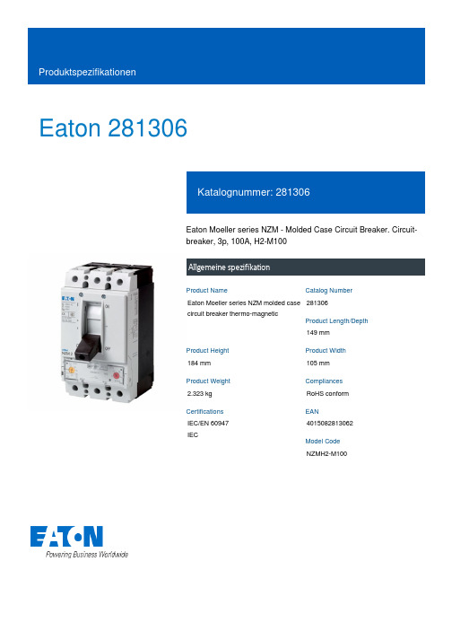
Eaton 281306Eaton Moeller series NZM - Molded Case Circuit Breaker. Circuit-breaker, 3p, 100A, H2-M100Allgemeine spezifikationEaton Moeller series NZM molded case circuit breaker thermo-magnetic281306149 mm184 mm 105 mm 2.323 kg RoHS conform IEC/EN 60947 IEC4015082813062NZMH2-M100Product NameCatalog NumberProduct Length/Depth Product Height Product Width Product Weight Compliances Certifications EANModel Code100 AIs the panel builder's responsibility. The specifications for the switchgear must be observed.5 kA130 kAMeets the product standard's requirements.Is the panel builder's responsibility. The specifications for the switchgear must be observed.Built-in device fixed built-in techniqueFixed100 ADoes not apply, since the entire switchgear needs to be evaluated.Max. 10 segments of 24 mm x 0.8 mm at rear-side connection (punched)Min. 2 segements of 16 mm x 0.8 mm at rear-side connection (punched)Max. 10 segments of 16 mm x 0.8 mm at box terminalMax. 8 segments of 24 mm x 1 mm (2x) at box terminal Min. 2 segments of 9 mm x 0.8 mm at box terminalRocker leverMeets the product standard's requirements.40 °C eaton-circuit-breaker-let-through-current-nzm-mccb-characteristic-curve-005.epseaton-circuit-breaker-characteristic-power-defense-mccb-characteristic-curve-037.epsMH2-M100il01206006z2015_11.pdfDas neue digitale NZM-Sortiment - In Kurze verfugbar DE Vorstellung des neuen digitalen Leistungsschalter NZMDA-CD-nzm2_3pDA-CS-nzm2_3peaton-manual-motor-starters-starter-nzm-mccb-wiring-diagram.eps eaton-manual-motor-starters-starter-msc-r-reversing-starter-wiring-diagram.epseaton-nzm-technical-information-sheeteaton-circuit-breaker-nzm-mccb-dimensions-019.epsRated operational current for specified heat dissipation (In) 10.11 Short-circuit ratingRated short-circuit breaking capacity Ics (IEC/EN 60947) at 690 V, 50/60 HzRated short-circuit breaking capacity Icu (IEC/EN 60947) at 400/415 V, 50/60 Hz10.4 Clearances and creepage distances10.12 Electromagnetic compatibilityMounting MethodAmperage Rating10.2.5 LiftingTerminal capacity (copper strip)Handle type10.2.3.1 Verification of thermal stability of enclosuresAmbient storage temperature - min Characteristic curveeCAD model Installationsanleitung Installationsvideos mCAD modelSchaltpläneTechnische Datenblätter ZeichnungenFitted with:Thermal protectionProtection against direct contactFinger and back-of-hand proof to VDE 0106 part 100Terminal capacity (copper busbar)M8 at rear-side screw connectionMax. 24 mm x 8 mm direct at switch rear-side connectionMin. 16 mm x 5 mm direct at switch rear-side connection10.8 Connections for external conductorsIs the panel builder's responsibility.Special featuresMaximum back-up fuse, if the expected short-circuit currents at the installation location exceed the switching capacity of the circuit breaker (Rated short-circuit breaking capacity Icn) Rated current = rated uninterrupted current: 100 A Tripping class 10 A IEC/EN 60947-4-1, IEC/EN 60947-2 The circuit-breaker fulfills all requirements for AC-3 switching category.Ambient operating temperature - max70 °CClimatic proofingDamp heat, constant, to IEC 60068-2-78Damp heat, cyclic, to IEC 60068-2-30Terminal capacity (aluminum stranded conductor/cable)25 mm² - 185 mm² (1x) at tunnel terminal25 mm² - 50 mm² (1x) direct at switch rear-side connection25 mm² - 50 mm² (2x) direct at switch rear-side connectionTerminal capacity (copper stranded conductor/cable)25 mm² - 185 mm² (1x) at 1-hole tunnel terminal25 mm² - 185 mm² (1x) at box terminal25 mm² - 185 mm² (1x) direct at switch rear-side connection25 mm² - 70 mm² (2x) at box terminal25 mm² - 70 mm² (2x) direct at switch rear-side connectionLifespan, electrical5000 operations at 690 V AC-36500 operations at 415 V AC-37500 operations at 690 V AC-110000 operations at 400 V AC-16500 operations at 400 V AC-310000 operations at 415 V AC-1Electrical connection type of main circuitScrew connectionShort-circuit total breaktime< 10 msRated impulse withstand voltage (Uimp) at main contacts8000 VRated short-circuit breaking capacity Ics (IEC/EN 60947) at 400/415 V, 50/60 Hz130 kA10.9.3 Impulse withstand voltageIs the panel builder's responsibility.Utilization categoryA (IEC/EN 60947-2)Number of polesThree-poleAmbient operating temperature - min-25 °C10.6 Incorporation of switching devices and componentsDoes not apply, since the entire switchgear needs to be evaluated.10.5 Protection against electric shockDoes not apply, since the entire switchgear needs to be evaluated.Terminal capacity (control cable)0.75 mm² - 1.5 mm² (2x)0.75 mm² - 2.5 mm² (1x)Equipment heat dissipation, current-dependent25.65 WInstantaneous current setting (Ii) - min800 A10.13 Mechanical functionThe device meets the requirements, provided the information in the instruction leaflet (IL) is observed.10.2.6 Mechanical impactDoes not apply, since the entire switchgear needs to be evaluated.10.9.4 Testing of enclosures made of insulating materialIs the panel builder's responsibility.Rated operational current99 A (400 V AC-3)Rated short-circuit breaking capacity Ics (IEC/EN 60947) at 230 V, 50/60 Hz150 kAApplicationUse in unearthed supply systems at 690 V10.3 Degree of protection of assembliesDoes not apply, since the entire switchgear needs to be evaluated.Rated short-circuit making capacity Icm at 240 V, 50/60 Hz330 kARated short-circuit breaking capacity Ics (IEC/EN 60947) at 440 V, 50/60 Hz130 kADegree of protection (IP), front sideIP40 (with insulating surround)IP66 (with door coupling rotary handle)Rated short-circuit making capacity Icm at 525 V, 50/60 Hz105 kARated short-circuit making capacity Icm at 690 V, 50/60 Hz40 kAInstantaneous current setting (Ii) - max1250 AOverload current setting (Ir) - min80 A10.2.3.2 Verification of resistance of insulating materials to normal heatMeets the product standard's requirements.10.2.3.3 Resist. of insul. mat. to abnormal heat/fire by internal elect. effectsMeets the product standard's requirements.Lifespan, mechanical20000 operationsOverload current setting (Ir) - max100 AVoltage rating690 V - 690 VTerminal capacity (copper solid conductor/cable)6 mm² - 16 mm² (2x) at box terminal10 mm² - 16 mm² (1x) direct at switch rear-side connection6 mm² - 16 mm² (2x) direct at switch rear-side connection16 mm² (1x) at tunnel terminal10 mm² - 16 mm² (1x) at box terminalDegree of protection (terminations)IP00 (terminations, phase isolator and strip terminal)IP10 (tunnel terminal)10.9.2 Power-frequency electric strengthIs the panel builder's responsibility.Short-circuit release non-delayed setting - min800 ADegree of protectionIP20 (basic degree of protection, in the operating controls area) IP20Overvoltage categoryIIIRated short-time withstand current (t = 1 s)1.9 kARated impulse withstand voltage (Uimp) at auxiliary contacts 6000 VTerminal capacity (aluminum solid conductor/cable)10 mm² - 16 mm² (1x) direct at switch rear-side connection10 mm² - 16 mm² (2x) direct at switch rear-side connection16 mm² (1x) at tunnel terminalSwitch off techniqueThermomagneticRated short-time withstand current (t = 0.3 s)1.9 kAAmbient storage temperature - max70 °CRated short-circuit breaking capacity Ics (IEC/EN 60947) at 525 V, 50/60 Hz37.5 kAOptional terminalsBox terminal. Connection on rear. Tunnel terminalRelease systemThermomagnetic releasePollution degree310.7 Internal electrical circuits and connectionsIs the panel builder's responsibility.Rated operating power at AC-3, 230 V30 kW10.10 Temperature riseThe panel builder is responsible for the temperature rise calculation. Eaton will provide heat dissipation data for the devices.FunctionsMotor protectionShort-circuit release non-delayed setting - max1400 AStandard terminalsScrew terminalRated short-circuit making capacity Icm at 400/415 V, 50/60 Hz 330 kARated operating power at AC-3, 400 V55 kWTypeCircuit breaker10.2.2 Corrosion resistanceMeets the product standard's requirements.10.2.4 Resistance to ultra-violet (UV) radiationMeets the product standard's requirements.10.2.7 InscriptionsMeets the product standard's requirements.Rated short-circuit making capacity Icm at 440 V, 50/60 Hz 286 kAIsolation500 V AC (between auxiliary contacts and main contacts)300 V AC (between the auxiliary contacts)Number of operations per hour - max120Circuit breaker frame typeNZM2Direction of incoming supplyAs requiredShock resistance20 g (half-sinusoidal shock 20 ms)Eaton Konzern plc Eaton-Haus30 Pembroke-Straße Dublin 4, Irland © 2023 Eaton. Alle Rechte vorbehalten. Eaton ist eine eingetrageneMarke.Alle anderen Warenzeichen sindEigentum ihrer jeweiligenBesitzer./socialmedia1000 VRated insulation voltage (Ui)。
ELX1301系列10 x 38 mm EV熔断器产品介绍说明书
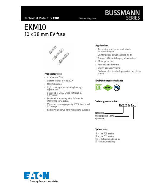
EKM1010 x 38 mm EV fuseProduct features• 10 x 38 mm fuse• Current rating: 10 A to 30 A • 1000 Vdc rating•High breaking capacity for high energy applications•Designed to JASO D622, ISO8820-8, GB/T31465•Produced in a factory with ISO9001 & IATF16949 certification•Minimum breaking capacity 300% In at rated DC voltage•Bolt-down and PCB terminal options availableApplications•Automotive and commercial vehicle on-board chargers• Uninterruptible power supplies (UPS) • 3-phase EVSE and charging infrastructure • Motor protection • Rectifiers and inverters • Energy storage systems•On-board electric vehicle powertrain and distri-butionEnvironmental complianceHALOGENHF FREEEKM10-30-SCTFamily codeAmpere rating (30 = 30 A)Option codeOrdering part numberPbOption code1P = 1 pin PCB terminal 2P = 2 pin PCB terminalSCT = Bolt down single cap tag AT = Bolt down axial tag2Technical Data ELX1301Effective May 2023EKM1010 x 38 mm EV fuse/electronicsElectrical characteristicsAmps (A)Minimum (seconds)Maximum (seconds)1.0 In 14400-2.0 ln 1.03003.0 ln 0.2305.0 ln0.110Product specificationsRated current Typical cold resistance 1Typical voltage drop Part numberRated voltage(A)Breaking capacity(mΩ)(mV)EKM10-101000 Vdc 101000 Vdc/50 kA 12.5180EKM10-151000 Vdc 151000 Vdc/50 kA 7.2160EKM10-201000 Vdc 201000 Vdc/50 kA 5.2150EKM10-251000 Vdc 251000 Vdc/50 kA 4.0160EKM10-301000 Vdc301000 Vdc/50 kA3.11601. Cold resistance is measured at <10% In and +25 °C ambient temperatureDimensions- mmTolerances unless otherwise specified One place x.x = ± 0.3 mmTwo places x.xx = ± 0.13 mm 1P: 1 pin PCB terminalSCT : Bolt-down single cap tagAT: Bolt down axial tag2P: 2 pin PCB terminalPCB layout 1P: 1 pin PCB terminalNote: recommend tightening torque is 4.5 ±1.0 Nm for M5 Screw PCB layout 2P: 2 pin PCB terminalPart markingNote: recommend tightening torque is 4.5 ±1.0 Nm for M5 Screw3Technical Data ELX1301Effective May 2023EKM1010 x 38 mm EV fuse /electronics Packaging informationGeneral specificationsOperating temperature: -40 °C to +125 °C with proper derating factor applied Strength of terminals: JASO D622 6.3.9, mounting torque 4.5 +/-1 Nm, 3 timesTemperature humidity cycling: JASO D622 6.3.4.1,a) maintain the samples at standard conditions for 4 hours b) increase T to 55 +/-2 °C at 95% to 99% RH within 0.5 hours c) maintain T at 55 +/-2 °C at 95% to 99% RH for 10 hoursd) decrease T to -40 +/-2 °C within 2.5 hours; the humidity is uncontrolled e) maintain T at -40 +/-2 °C for 2 hours; the humidity is uncontrolledf) increase T to 120 +/-2 °C within 1.5 hours from -40 +/-2 °C; the humidity is uncontrolled g) maintain T at 120 +/-2 °C for 2 hours; the humidity is uncontrolledh) allow to return to RT within 1.5 hours; the humidity is uncontrolled 10 cycles.Thermal shock: ISO8820-8 GB/T31465.6, 48 cycles; -40 °C to 100 °C, each cycle 60 minutes Vibration: JASO D622 6.3.3, 10-55 Hz, 3 directions, 2 hours each directionTransient current cycling: JASO D622 6.3.2 (reference), The transient current start from 2.0 In for 0.25 seconds, then drop to 0.5 In and keep this current to 15 seconds to finish one cycle, total 50000 cyclesLubricant & fuel oil resistance: GB/T31465.1-5.4, Wipe the marking with lubricant or oil 30 secondsTerminalsInner packageShip packageSCT 40 pieces/tray 400 pieces/box AT 20 pieces/box 540 pieces/box 1P 20 pieces/bag 540 pieces/box 2P20 pieces/box640 pieces/box4Technical Data ELX1301Effective May 2023EKM1010 x 38 mm EV fuse/electronics0.40.50.60.70.80.911.11.21.31.4-50-40-30-20-10102030405060708090100110120130T emperature derating curveCurrent vs. time curve 0.010.1110100101,000T i m e (s )10A20A 30A100Current (A)15A 25AD e r a t i n g f a c t o rT emperature (°C)I 2T vs. time curve1001,00010,000100,0001,000,00010,000,0000.010.11101001000I 2t (A 2s )10ATime (s)20A 30A 15A 25A5Technical Data ELX1301Effective May 2023EKM1010 x 38 mm EV fuse /electronics I 2t vs. current curve101001,00010,000100,000101,000I 2t (A 2s )15A25A30A100Current (A)20A 10AEatonElectronics Division 1000 Eaton Boulevard Cleveland, OH 44122United States/electronics© 2023 EatonAll Rights Reserved Printed in USAPublication No. ELX1301 BU-ELX22164May 2023EKM1010 x 38 mm EV fuseTechnical Data ELX1301Effective May 2023Life Support Policy: Eaton does not authorize the use of any of its products for use in life support devices or systems without the express writtenapproval of an officer of the Company. Life support systems are devices which support or sustain life, and whose failure to perform, when properly used in accordance with instructions for use provided in the labeling, can be reasonably expected to result in significant injury to the user.Eaton reserves the right, without notice, to change design or construction of any products and to discontinue or limit distribution of any products. Eaton also reserves the right to change or update, without notice, any technical information contained in this bulletin.T e m p e r a t u r eTimeT T T T Wave solder profile--PCB version onlyReference EN 61760-1:2006Profile featureStandard SnPb solderLead (Pb) free solderPreheat • Temperature min. (T smin )100 °C 100 °C • Temperature typ. (T styp )120 °C 120 °C • Temperature max. (T smax )130 °C 130 °C • Time (T smin to T smax ) (t s )70 seconds 70 seconds ∆ preheat to max Temperature150 °C max.150 °C max.Peak temperature (T P )*235 °C – 260 °C 250 °C – 260 °C Time at peak temperature (t p )10 seconds max5 seconds max each wave 10 seconds max5 seconds max each wave Ramp-down rate~ 2 K/s min ~3.5 K/s typ ~5 K/s max ~ 2 K/s min ~3.5 K/s typ~5 K/s max Time 25 °C to 25 °C4 minutes4 minutesManual solder+350 °C (4-5 seconds by soldering iron), generally manual/hand soldering is not recommended.Eaton is a registered trademark.All other trademarks are property of their respective owners.Follow us on social media to get the latest product and support information.。
人民电器 HR5系列熔断器式隔离开关 产品说明书
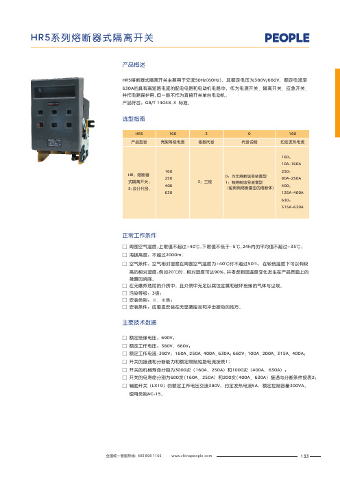
产品概述□ □ □ :□ □ □ □ 额定绝缘电压:690V 额定工作电压:380V 、660V 额定工作电流:380V 160A 、250A 、400A 、630A ;660V 100A 、200A 、315A 、400A 开关的接通和分断能力和额定限制短路电流按表1;开关的机械寿命分别为3000次(160A 、250A 和1000次(400A 、630A 开关的电寿命分别为600次(160A 、250A 和200次(400A 、630A 接通与分断条件按表2辅助开关(LX19的额定工作电压交流380V ,约定发热电流5A ,额定控制容量300VA , 使用类别AC-15。
;;:;));));)选型指南主要技术数据正常工作条件□ 周围空气温度:上限值不超过+40℃,下限值不低于-5℃,24h 内的平均值不超过+35℃;海拔高度:不超过2000m ;空气条件:空气相对湿度在周围空气温度为+40℃时不超过50%,在较低温度下可以有较 高的相对湿度;例如20℃时,相对湿度可达90%,并考虑到因温度变化发生在产品表面上的 凝露的消除。
在无爆炸危险的介质中,且介质中无足以腐蚀金属和破坏绝缘的气体与尘埃。
污染等级:3级;安装类别:Ⅱ、Ⅲ类;安装条件:应垂直安装在无显著摇动和冲击振动的地方。
□ □ □ □ □ □ HR5熔断器式隔离开关主要用于交流50Hz (60Hz ),其额定电压为380V/660V ,额定电流至630A 的具有高短路电流的配电电路和电动机电路中,作为电源开关、隔离开关、应急开关、并作电路保护用,但一般不作为直接开关单台电动机。
产品符合:GB/T 14048.3 标准。
133表1表2表3开关与熔断器的配用关系(见表)3结构特征开关由底座、盖和灭弧室等部分组成,均由耐弧塑料制成,为全塑型结构。
静触头直接装在底座上,灭弧室拆装方便,每个灭弧室都有内室 和外室二部分,采用多片金属灭弧栅,增强能力,提高了触头寿命。
人民电器 RDT16系列有填料封闭管式刀型触头熔断器 使用说明书
RD T16系列有填料封闭管式刀型触头熔断器符合标准:GB/T 13539.2警告:更换熔断体时,须确保熔断器前端的开关是断开状态!注意:1、必须由专职人员使用,且不得湿手操作,防止触电。
2、熔断体熔断后,应先查明原因,排除故障后再更换。
3、更换熔断体时:1)请用更换手柄进行更换,不要用手直接触碰熔断体,防止烫伤;2)必须选原规格的熔断体,不得用其它规格的熔断体代替。
4、运行中如果有两相熔断,更换熔断体时应同时更换三相。
一、概述:1、结构:RDT16(RT16)有填料封闭管式刀型触头熔断器(以下简称熔断器)主要由熔断体和支持件构成。
2、用途:主要用于交流50Hz ,额定电压500/660V ,额定电流1000A 及以下的工业配电装置中,作过载和短路保护之用。
3、符合标准:GB /T 13539.2。
熔断体额定电流三极熔断器尺码设计序号/三、主要技术参数:1、熔断器的主要技术参数和性能见表1。
RD T 16C 企业代号有填料封闭管式熔断器二、型号说明:表1尺码000132450066012500V120660V 1003545609010040063010002505001606支持件额定电流/A冲击耐受电压/kV 额定电压/V 分断能力/kA 耗散功率/W 熔断体额定电流/A 315,400,500,630800,10004,6,10,16,20,25,32,4050,63,80,100,125,1606,10,16,20,25,32,40,50,63,80,100,125,16080,100,125,160,200,250125,160,200,250,315,4002、熔断体的技术参数见表2。
四、使用和维护:1、周围空气温度(-5~+40)℃,且24h 的平均值不超过+35℃。
4<In <1616≤In ≤6363<In ≤160160<In ≤400In >400234In ≤42.1In 1.9In1.6In1.5In 1.5In1.25In1If Inf 约定电流/A 约定时间/h“gG ”熔断体额定电流In(A)表 2空气相对湿度在周围温度为+40℃时不超过50%。
- 1、下载文档前请自行甄别文档内容的完整性,平台不提供额外的编辑、内容补充、找答案等附加服务。
- 2、"仅部分预览"的文档,不可在线预览部分如存在完整性等问题,可反馈申请退款(可完整预览的文档不适用该条件!)。
- 3、如文档侵犯您的权益,请联系客服反馈,我们会尽快为您处理(人工客服工作时间:9:00-18:30)。
一、西安西熔电力科技有限公司
1、3.6-40.5kv高压限流熔断器
本产品适用于户内50Hz,额定电
压3.6-40.5kV系统作为电压互感器的过载或短路保护之用,(通过国家高压电器质量监督检测中心试验,产品符合GB/T15166.2和IEC60282-1)。
(1)型号
(2)基本参数
熔断器的基本参数如表:
(3)外型及安装尺寸
熔断器的外型及安装尺寸如(图3)和表2所示;
2、40.5KV高压限流熔断器
40.5KV高压限流熔断器
本产品适用于户内交流50Hz,额定电压40.5kV电力系统,作为高压电力变压器及其它电力设备过载或短路等保护元件,还可与其它保护电器(负荷开关,真空断路器等)配合使用。
(1)型号
(2)基本参数
熔断器的基本参数如表:
(3)外型及安装尺寸
熔断件的外型尺寸如(图3)
熔断器的外型及安装尺寸如(图4):
(4)熔断器的选用
用于变压器初级端熔断器的一般选用原则见表:
3、RN系列高压交流熔断器
RN系列高压交流熔断器
本系列高压交流熔断器适用于户内交流50Hz,额定电压3kV-35kV电力系统,用于对电力线路、变压器、电压互感器及其它电器的过载及短路保护,亦可用以保护电力系统分出的支路,当线路短路电流达到最大值之前熔断器就将线路切断。
(1)型号
熔断器的基本参数如表:
表一
注:*号为双拼管
表二
注:*号为双拼管
(3)外型及安装尺寸
RN1、RN3型户内高压熔断器外形尺寸如(图1)、(图2)和表3所示;
图1
图2 表三
( )为RN,RN3-6外形尺寸
RN2型户内高压熔断器外形尺寸如(图3)、(图4)及表4
图3
图4
表四。