BROOKFIELD CT3质构仪(LFRA,QTS升级版&凝胶标准仪器)
美国Brookfield公司的发展
第33卷第1期明胶科学与技术2013年3月T he Sci ence and T echn ol ogy of G e l a t i n V01.33.N o.1 M a s.2013.美国B r ookf i el d公司的发展蒋楠+美国Br ookf i el d公司中国代表处,北京,100029“2m nk vi s cos i t y.t hi nk B r ookf i el d.Thi nk t ex—t ur e,t hi nk B r ookf i el d”.当您遇到粘度问题、质构分析问题时,就会想到美国B r ookf i el d公司的粘度计、组织分析仪(也称质构仪)。
美国B r ookf i el d公司是当今世界上首屈一指的粘度计、质构仪、流变仪以及粉体流动测试仪生产商,在全球拥有极高的声誉。
B r ookf i el d总部位于美国马萨诸塞州的M i ddl e—bor o,占地93000平方英尺。
美国B r ookf i el d公司于2001年在中国成立了代表处暨技术服务中心,分别设在北京、上海和广州三个城市。
80多年的专业研发和行业领先技术,B r ookf i el d凭借其产品的精确度、可重复性和高性价比,已经成为国际多个领域质量控制的重要检测设备。
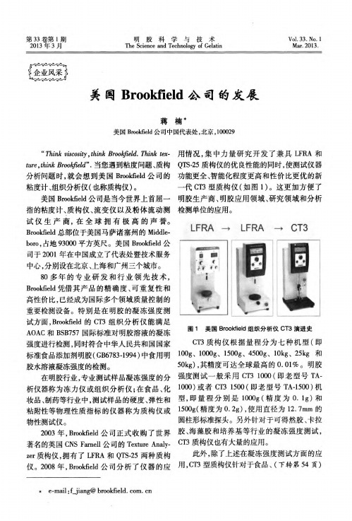
特别是在明胶的凝冻强度测试方面,Br ookf i e l d的C T3组织分析仪能满足A O A C和B SB757国际标准对明胶溶液的凝冻强度进行检测,同时符合中华人民共和国国家标准食品添加剂明胶(G B6783.1994)中食用明胶水溶液凝冻强度的检测。
在明胶行业,专业测试样品凝冻强度的分析仪器称为冻力仪或组织分析仪;在食品、化妆品、制药等行业中,测试样品的硬度、弹性和粘附性等物理性质指标的仪器称为质构仪或物性测试仪。
2003年,B r ookf i el d公司正式收购了世界著名的英国C N S Fam e l l公司的T ext ur e A nal y.zer质构仪,拥有了L FR A和Q T S-25两种质构仪。
CT3质构仪操作手册

目录
I. 介 绍 .......................................................................................................................................................................................... 3 I.1 仪器组成 ........................................................................... ......................................................... 3 I.2 电源 .............................................................................................................................................4 I.3 单位..................................................... ........................................................................................ 4 I.4 技术指标..................................................................... ................................................................ 4 I.5 仪器安装 .................................................................... ................................................................ 5 I.6 安全标志和警告 ........................................................................................................................ 6 I.7 按键功能 .................................................................................................................................... 7 I.8 仪器清洁 .......................................................................................................................................8
GWS3TS 體重體脂測量儀 使用指南说明书

for the weight calculating result, the correct weight will be displayed on the LCD screen.
Tips: The automatic switch on function is only activated for weight function only. You have to input your personal parameters to measure the weight, body fat, water mass, muscle mass, bone mass, calorie and BMI.
2
PARTS IDENTIFICATION
Before using the scale for the first time, please be familiar with all of the parts. Read all Instructions and Safeguards carefully.
user number.
Set Gender • The gender icon will flash on the LCD display. • Press “UP( )” or “DOWN( )” button to select male ( ) or female ( ) icon. For
罗克韦尔自动化 FactoryTalk Alarms and Events 系统配置指南说明书

章节 4
在 Studio 5000 控制器中定 义基于设备的报警
控制器连接丢失时的报警缓冲 ............................................................... 27 在开始之前 ................................................................................................28 先决条件 ....................................................................................................28 遵照下列步骤............................................................................................ 28 定义基于 Logix 标签的报警................................................................. 28
警告:标识可能导致暴露于危险环境从而造成人员伤亡、财物损害或经济损失的做法或环境的相关信息。
注意:标识可能导致人员伤亡、财物损害或经济损失的做法或环境的相关信息。注意事项可帮助您识别危险,避开 危险,以及意识到后果。
重要 标识对成功应用和了解产品至关重要的信息。 还会在设备上或内部使用标签来提供具体预防措施。
典型的独立系统 ................................................................................. 24 安装 FactoryTalk 软件.................................................................... 25 安装 Microsoft SQL Server .............................................................. 26
美国UC3-CT-A平衡器用户手册说明书

R e t a i l S c a l e sA logical merger of PC and scaleThe UC3-CT-A is a high-performance scale of the latest generation of UCs, focusing on users and customers. touchscreen, which is freely customisable in all respects, incorporates these aspects Our flat series saves space and provides UC3-CT-ATechnical dataUC3-CT-ACapability CharacteristicsOnline help: Operative assistance via text displays Competence text for the operatorReceipt reversal via the receipt number Extensive taring options Proof of origin (optional)Promotions (optional)Receipt enhancement (optional)Cash register modules (optional)• Cash register functions • Coin count**DisplayMonochrome STN display, VGA resolution 320 x 240 pixels Colour STN display, VGA resolution 320 x 240 pixels (optional)The display is made for the operator via a 10.4-inch colour touch-screen (resolution 800 x 600)Weight display with 5 characters 5-character tare displayFlat rate display with 8 charactersTotal amount display with 9 characters3-line text display, 20 characters per line (customer page)Coloured texts advertising on the customer displayOperation typesOperation, labelling, bulk, operation with receipt and total label, receipt and article label, stick-on total receipts, receipt with/without counterfoil Classic – by inputting the PLU number, via presets or via alphanumeric search functions, hits can be posted immediately Freely definable user layoutsPrinterChoose from a 2“ or 3“ label printer and 2“ receipt printer (standard)Possible as a 2“ linerless printer Fast label printer, up to 125 mm/s Logo printing onto receipt or labelFreely definable labels (for free designing of the labels on the PC, we offer our WYSIWYG program UC3 Label)Data MemoryMin. 40 GB hard disk256 MB RAM, 512 MB optionalSecurityPassword protection for important functions Local core database** only in combination with cash register functions/retailMore InformationQuality management certificate ISO 9001Environmental management certificate ISO 14001Internet: Worldwide ServiceSubject to technical changes ©082007 Mettler-Toledo GmbH Printed in Germany 22014468MCG MarCom GreifenseeMultimedia web support Flash Player (optional)InterfacesEthernet TCP/IP 10/1001 x RS232 serial interface1 x RJ11 interface for triggering of a cash register drawer2 x USB 2.0 connections Optional:Wireless solution according to IEEE 802.11b/g Remote service/control and data supply FTP VNCData communication via Trans UC3Data supply and disposal via XML interfaceOperating SystemMicrosoft Windows Embedded for Point Of Service (WEPOS)Linux (optional)Weighing area 6kg 15kg 3kg/6kg6kg/15kg 12kg 30kg Division 2g 5g 1g/2g 2g/5g 2g 5g Min. load* 40g 100g20g40g40g100g* EC: Printing is possible for the minimum load, however not when labelling. Taring comparison throughout the entire weighing area; automatic zeroposition.• Outstanding ergonomics – thanks to adjustment options for the customer display and touchscreen• Alphanumeric searching – just a few letters to the target of generating additional sales• Cross-selling at a high level universal networking capability; via wifi (WLAN) optionally available。
生物实验室仪器国际知名品牌简介

生物实验室仪器国际品牌简介1、赛默飞世尔科技(热电)Thermo Fisher Scientific :2006年11月9日,热电公司与飞世尔科学国际公司合并完成,Thermo Fisher Scientific公司成立。
科学仪器行业最大的供应商由此诞生:合并后,公司年销售额将达到约90亿美元(是第二名销售额的三倍),全球员工约30000名。
Thermo Fisher Scientific公司将拥有两个旗舰品牌——Thermo Scientific和Fisher Scientific:Thermo Scientific 代表可提供综合实验室工作流程解决方案的广泛高端分析仪器、化学品和耗材、实验室设备、软件与服务。
Thermo Scientific 是倍受信赖品牌 Thermo Electron 的新名称,保留原Thermo 旗下的所有优质仪器并融入原Fisher旗下的某些高科技品牌,以提供完整的从实验室到生产乃至产品包装的整个过程一体化仪器解决方案。
具有世界一流的竞争力,比同类竞争对手涵盖的领域更广泛、全面。
Fisher Scientific 代表公司全球分销和服务品牌,包括用于保健、科学研究、安全和教育的实验室设备、化学品、耗材和服务的完整产品系列。
Fisher Scientific将这些解决方案带给全世界的常规研究客户,此外,通过Fisher HealthCare、Fisher Safety 和 Fisher Science Education,Fisher公司为客户提供他们所需要的专业设备、耗材和服务,以及满足他们需要这些产品的方式。
中国区总裁Lew Rosenblum(罗瑞德)介绍,公司目前在中国已有四处生产基地:上海浦东区两个生产基地面积分别为8300平方米和2000平方米,可生产分析仪器、过程仪表和实验室仪器设备等;位于上海南汇区的工厂面积达9000平方米,主要生产显微镜载玻片产品;位于北京的面积达1000平方米的生产基地,则主要生产生化类产品,如Hyclone培养基等。
KSZ8873MLL FLL RLL 评估板用户指南说明书

KSZ8873MLL/FLL/RLLEvaluation Board User’s GuideKSZ8873MLL/FLL/RLL Integrated 3-Port 10/100 Managed Switch with PHYsRevision 1.1 January 2011© Micrel, Inc. 2011All rights reservedMicrel is a registered trademark of Micrel and its subsidiaries in theUnited States and certain other countries. All other trademarks are theproperty of their respective owners.The information furnished by Micrel in this datasheet is believed to be accurate and reliable. However, no responsibility is assumed by Micrel for its use. Micrel reserves the right to change circuitry and specifications at any time without notification to the customer. Micrel Products are not designed or authorized for use as components in life support appliances, devices or systems where malfunction of a product can reasonably be expected to result in personal injury.Life support devices or systems are devices or systems that (a) are intended for surgical implant into the body or (b) support or sustain life, and whose failure to perform can be reasonably expected to result in a significant injury to the user.A Purchaser's use or sale of Micrel Products for use in life support appliances, devices or systems is at Purchaser's ownrisk and Purchaser agrees to fully indemnify Micrel for any damages resulting from such use or sale.Revision HistoryRevision Date Summary of Changes1.0 06/30/09 Initial Release1.1 01/11/11 Update descriptionMicrel, Inc. January 11, 2011Table of Contents1.0Introduction (4)2.0Board Features (4)3.0Evaluation Kit Contents (4)4.0Hardware Description (4)4.1Strap In Mode (5)4.1.1Feature Setting Jumpers (6)4.2I2C Master (EEPROM) Mode (7)4.3SPI Slave Mode (8)4.410/100 Ethernet PHY Ports (KSZ8873MLL/RLL) (9)4.5100FX Fiber Port (KSZ8873FLL) (9)4.6LED Indicators (9)4.7MII Port Configuration (KSZ8873MLL/FLL) (9)4.8RMII Port Configuration (KSZ8873RLL) (10)5.0Reference Documents (10)List of TablesTable 1: Feature Setting Jumpers (6)Table 2: Reserved Jumpers (7)Table 3: EEPROM Mode Settings (8)Table 4: SPI Slave Mode Settings (8)Table 5: LED Modes (9)Table 6: RMII Clock Setting (10)List of FiguresFigure 1: KSZ8873MLL/FLL/RLL Evaluation Board Block Diagram (5)Micrel, Inc. January 11, 20111.0 IntroductionThe KSZ8873MLL/FLL/RLL is Micrel’s third generation fully integrated 3-port switch. The two PHY units of KSZ8873MLL/RLL support 10BASE-T and 100BASE-TX. The KSZ8873FLL supports 100BASE-FX. The devices have been designed for cost sensitive systems, however, still offer a multitude of features, such as switch management, port and tag based VLAN, QoS priority, one MII interfaces and CPU control and data interfaces.The KSZ8873MLL/FLL/RLL is an excellent choice for VoIP Phone, Set-top/Game Box, SOHO Residential Gateway, industrial Ethernet systems and as a standalone 3-port switch.The KSZ8873MLL/FLL/RLL Evaluation Board provides a convenient means to evaluate the KSZ8873MLL/FLL/RLL’s rich feature set. Easy access is provided to all of the KSZ8873MLL/FLL/RLL pins, with jumpers and interface connectors allowing quick configuration and re-configuration of the board. MIIM, EEPROM programming, SPI emulation software are also provided to access the more extensive features of the KSZ8873MLL/FLL/RLL, via a PC USB port.2.0 Board Features•Micrel’s KSZ8873MLL/FLL/RLL Integrated 3-Port 10/100 Managed Ethernet Switch•Two RJ-45 Jacks for Ethernet LAN Interfaces with corresponding Isolation Magnetics (KSZ8873MLL/RLL)•Auto MDI/MDI-X on the PHY port• 1 PHY Mode and 1 MAC Mode MII Connectors for the Switch RMII/MII Interface• 2 100Base-FX fiber interface(KSZ8873FLL)• 1 USB port to emulate an MIIM, EEPROM, SPI Interface•On board EEPROM• 2 LEDs per port to Indicate the Status and Activity of the RJ45 port• 1 power jack for 5VDC Universal Power Supply3.0 Evaluation Kit ContentsThe KSZ8873MLL/FLL/RLL Evaluation kit includes the following:•KSZ8873MLL/FLL/RLL Evaluation Board Revision 1.0•KSZ8873MLL/FLL/RLL Evaluation Board User’s Guide•Micrel Switch Configuration Software Version 1.0.5•Micrel Switch Configuration Software User Guide•KSZ8873MLL/FLL/RLL Evaluation Board Schematic Revision 1.0(Contact your Micrel FAE for the latest schematic)Note: USB cable and 5V DC Wall Power Supply is not included in the design kit (the dimension of the output plug of 5V DC wall power supply is 2.5x5.5x9.5mm or 0.1x0.218x0.375inch)4.0 Hardware DescriptionThe KSZ8873MLL/FLL/RLL Evaluation Board is in a compact form factor and can sit on a bench near a computer. There are three options for configuration: strap in mode, EEPROM mode, and SPI mode. Strap in mode configuration is easily done with on board jumper options. EEPROM mode and SPI mode are accomplished through a built in USB port interface. With the Micrel software and your PC, you can use the USB port to reprogram the EEPROM on board, or use the SPI interface to access the KSZ8873MLL/FLL/RLL’s full feature set. The board also features oneMicrel, Inc. January 11, 2011MII connector for the Switch MII interface. It is to facilitate connection from the switch to either the external CPU or the external PHY.Figure 1: KSZ8873MLL/FLL/RLL Evaluation Board Block DiagramThe KSZ8873MLL/FLL/RLL evaluation board is easy to use. There are programmable LED indicators for link and activity on the PHY ports and a power LED. A manual reset button allows the user to reset the board without removing the power plug. The 5V power on the board can be supplied by a standard 5VDC power supply (close pin 1-2 of JP400 jumper) or by the USB cable (close pin 2-3 of JP400 jumper) which is used to access the registers in SPI mode. A standard 5VDC power supply is included so that the user can supply power from any 110 Volt AC wall or bench socket. Before to start to use the evaluation board, make sure the power connectors JP403, JP404, JP405 and JP31 are connected, and close pin 1-2 of J14.4.1 Strap In ModeStrap in configuration mode is the quickest and easiest way to get started. In this mode, the KSZ8873MLL/FLL/RLL acts as a standalone 3-port switch. Simply set the board’s configuration jumpers to the desired settings and apply power to the board. The configuration can be changed while power is applied to the board by changing the jumper settings and pressing the convenient manual reset button for the new settings to take effect. Note that even if no external strap in values are set, internal pull up and pull down resistors will set the KSZ8873MLL/FLL/RLL default configuration. Section 4.1.1 covers each jumper on the board and describes its function. To start in strap in configuration mode, make sure that the USB cable is unplugged, JP34, JP35, JP3and JP9 are connected, JP21, JP25 have jumpers fitted between pins 2 to 3.Micrel, Inc. January 11, 20114.1.1 Feature Setting JumpersThe evaluation board provides jumpers to allow easy setting of strap in configurations for the KSZ8873MLL/FLL/RLL. Table 1 describes the jumpers and their functionalities.Table 1: Feature Setting JumpersOPEN CLOSED JUMPER KSZ8873MLL/FLL/RLLSIGNALJP3 SPIQ SPI EEPROMJP25 P2LED0 EEPROM/SPI Setting. See Section 4.2 and 4.3JP21 P2LED1 EEPROM/SPI Setting. See Section 4.2 and 4.3JP26 SMRXDV3 P3 MII Setting. Pull Up: PHY mode, Pull Down: MACmodeJP78 FXSD1 Pins 1-2 closed : Disable FEF feature of FX.Pins 5-6 closed : Force port 1 TX modeFor KSZ8873MLL/RLL, close 5-6 since this devicedoesn’t support FX mode.For KSZ8873FLL, open JP77JP77 FXSD2 Pins 1-2 closed : Disable FEF feature of FX.Pins 5-6 closed : Force port 1 TX modeFor KSZ8873MLL/RLL, close 5-6 since this devicedoesn’t support FX mode.For KSZ8873FLL, open JP77JP2 PWRDN Normal Operation KSZ8873MLL/FLL/RLLChip Power DownJP101 P1FFC Pull Down = DisablePull Up(default) = EnableJP102 P1DPX Pull Down = Half DuplexPull Up(default) = Full DuplexJP103 P1SPD Pull Down = 10BTPull Up(default) = 100BTJP104 P1ANEN Pull Down = DisablePull Up(default) = EnableJP201 SMRXD30(P2FFC) Pull Down = DisablePull Up(default) = EnableJP202 SMRXD31(P2DPX) Pull Down = Half DuplexPull Up(default) = Full DuplexJP203 SMRXD32(P2SPD) Pull Down = 10BTPull Up(default) = 100BTJP204 SMRXD33(P2ANEN) Pull Down = DisablePull Up(default) = EnableJP301 P1LED1(P3FFC) Pull Down = DisablePull Up(default) = EnableJP302 P1LED0(P3DPX) Pull Down(default) = Full DuplexPull Up = Half DuplexJP303 P3SPD Pull Down(default) = 100BTPull Up = 10BTJP304 SPIQ(XCLK) Pull Down = 50MHzPull Up(default) = 25MHzNote: JP101, JP102, JP103, JP201, JP202, JP203 are only valid if Auto-Negotiation is disabled.Micrel, Inc. January 11, 2011The following table shows the recommended settings for the evaluation board reserved jumpers.Table 2: Reserved JumpersJUMPER Description Recommended SettingJP79 MDC_PHY,MDIO_PHY OpenJP27 P3 MII configuration(For test only)OpenJP30 3.3V Biased of transformerCenter (For test only)OpenJP11 Power for Fiber Module.(Port 2) KSZ8873MLL/RLL: Open For KSZ8873FLL:Close pin 1-2 for 3.3V Fiber Module.Close pin 3-2 for 5.0V Fiber Module.JP10 Power for Fiber Module.(Port 1) KSZ8873MLL/RLL: Open For KSZ8873FLL:Close pin 1-2 for 3.3V Fiber Module.Close pin 3-2 for 5.0V Fiber Module.JP28 REFCLKO3 enable. KSZ8873MLL/FLL: OpenKSZ8873RLL:Close pin 1-2: Enable REFCLKOClose pin 2-3: Disable REFCLKO4.2 I2C Master (EEPROM) ModeThe evaluation board has an EEPROM to allow the user to explore more extensive capabilities of the KSZ8873MLL/FLL/RLL. The user can conveniently program the EEPROM on board using the USB port from any computer with a WIN 2000/XP environment and the Micrel provided software. This makes it easy for the user to evaluate features like “broadcast storm protection” and “rate control”.To prepare the KSZ8873MLL/FLL/RLL evaluation board for EEPROM configuration follow these steps:1. Install the Micrel Switch Configuration Software to your computer.2. Set JP3, JP9, JP21, JP25, JP34 and JP35 as specified in Table 3 for EEPROM modeconfiguration. Make sure that the EEPROM is installed on the board.3.Connect the computer’s USB port to the KSZ8873MLL/FLL/RLL board with aUSB port cable.4. There are two way to power up the evaluation board:a). Connect the 5 VDC power supply to the KSZ8873MLL/FLL/RLL when JP400pin1-2 is closed.b). 5 VDC power source from the USB port when JP400 pin 2-3 is closed.Micrel, Inc. January 11, 20115. The KSZ8873MLL/FLL/RLL will power up in its default configuration if there is noinformation in the EEPROM.6. Click the software icon to invoke the software to program the desired settings into theEEPROM. See the Micrel Switch Configuration Software User Guide for details.7. Press the manual reset button. The KSZ8873MLL/FLL/RLL will reset and read the newconfiguration in the EEPROM. After reset, the KSZ8873MLL/FLL/RLL is ready for normal operation.Table 3: EEPROM Mode SettingsJumper Description SettingJP9 SPIQ ClosedJP3 SCL_MDC_SW ClosedJP34 SCL_MDC ClosedJP35 SDA_MDIO ClosedJP25 Serial Bus Config. (P2LED0) Pins 2-3 closedJP21 Serial Bus Config. (P2LED1) Pins 2-3 closed4.3 SPI Slave ModeFrom SPI interface to the KSZ8873MLL/FLL/RLL, use a USB to SPI converter that allows accessing all of the KSZ8873MLL/FLL/RLL features and registers. The user can easily access the SPI interface using a computer connected to the evaluation board’s USB port interface. Micrel provides a Windows 2000/XP based program for the user to evaluate the KSZ8873MLL/FLL/RLL’s full feature set. In addition to all the registers available via EEPROM programming, a host CPU connected to theKSZ8873MLL/FLL/RLL’s SPI interface will be able to access all static MAC entries, the VLAN table, dynamic MAC address table and the MIB counters.To prepare the KSZ8873MLL/FLL/RLL evaluation board for SPI modeconfiguration follow these steps:1. Install the Micrel Switch Configuration Software on your computer.2. Set JP3, JP9, JP21, JP25, JP34 and JP35 as specified in Table 4 for SPI modeconfiguration.Table 4: SPI Slave Mode SettingsJumper Description SettingJP9 SPIQ OpenJP3 SCL_MDC_SW OpenJP34 SCL_MDC ClosedJP35 SDA_MDIO ClosedJP25 Serial Bus Config. (P2LED0) Pins 2-3 closedJP21 Serial Bus Config. (P2LED1) Pins 1-2 closed3.Connect the computer’s USB port to the KSZ8873MLL/FLL/RLL board with a Micrel, Inc. January 11, 2011USB port cable.4.There are two way to power up the evaluation board:a). Connect the 5 VDC power supply to the KSZ8873MLL/FLL/RLL when JP400pin1-2 is closed.b). 5 VDC power source from the USB port when JP400 pin 2-3 is closed.5.The KSZ8873MLL/FLL/RLL will power up in its default configuration6.Click the software icon to invoke the software to program the desired settings.See the Micrel Switch Configuration Software User Guide for details.4.4 10/100 Ethernet PHY Ports (KSZ8873MLL/RLL)There are two 10/100 Ethernet PHY ports on the KSZ8873MLL/RLL evaluation board. The ports can be connected to an Ethernet traffic generator or analyzer via standard RJ-45 connectors using CAT-5 cables. Each port can be used as either an uplink or downlink. Both ports support auto MDI/MDI-X, eliminating the need for cross over cables.4.5 100FX Fiber Port (KSZ8873FLL)There are two 100FX PHY ports on the KSZ8873FLL evaluation board. The ports can be connected to an Ethernet traffic generator or analyzer via fiber transceiver and fiber cable. The fiber signal threshold can be set by register 192 bit 6(Port1) and bit 7(Port2). If the bits are 1, the threshold will be set to 2.0V, Otherwise it is 1.25V.The resister R76 also need to be adjusted if the FXSD signal value from the fiber module doesn’t meet the fiber signal threshold spec.4.6 LED IndicatorsThere is one column of LED indicator for one column for port 2. The LED indicators are programmable to three different modes. LED mode is selected through register 195 bit [5:4] setting. The LED mode definitions are specified in Table 5. See Figure 1 for the LEDs’ orientation on the KSZ8873MLL/FLL/RLL evaluation board.Table 5: LED ModesRegister 195 Bit[5:4]00 01 10 11PxLED1 = Speed PxLED1 = Active PxLED1 = Duplex PxLED1 = Duplex PxLED0 = Link/Active PxLED0 = Link PxLED0 = Link/Active PxLED0 = LinkThe KSZ8873MLL/FLL/RLL evaluation board provides two LEDs (PxLED1, PxLED0) for each PHY port.The KSZ8873MLL/FLL/RLL evaluation board also has a power LED (D3) for the 3.3V power supply. When D3 is lit, the board’s 3.3V power supply is “on”.4.7 MII Port Configuration (KSZ8873MLL/FLL)The evaluation board provides access to the KSZ8873MML’s MAC via the MII port interfaces. The MAC can be configured to MII PHY mode and MII MAC mode. To configure the MAC, the board’s jumpers JP27 is set as specified in Table 6.Micrel, Inc. January 11, 2011Micrel, Inc. January 11, 2011Table 6: MII Mode SettingsMII Mode MII PHY mode MII PHY mode JP27 for Port 1Pins 1-2 closedPins 2-3 closedIn MII PHY mode, the MII transmit and receive signals will be on J3, the male MII port connectors. This mode is usually used to connect the KSZ8873MML to an external MAC processor. In MII MAC mode, the MII transmit and receive signals will be on J4, the female MII port connector. This interface is normally used to connect the KSZ8873MML to an external PHY, for example the Micrel KSZ8041NL.4.8 RMII Port Configuration (KSZ8873RLL)In RMII interface, the 50MHz reference clock can be provide by the KSZ8873RLL or by the link partner. When pin 1-2 of JP28 is closed, the reference clock will be output from REFCLKO on KSZ8873RLL. Register 198 bit[3] is used to select internal or external reference clock for the KSZ8873RLL RMII interface. If pin 2-3 of JP28 is closed, the REFCLKO disable.Table 7: RMII Clock Setting5.0 Reference DocumentsKSZ8873MLL/FLL/RLL Datasheet Rev. 1.1 (Contact Micrel for latest Datasheet)KSZ8873MLL/FLL/RLL Evaluation Board Schematic Rev. 1.0 (Contact Micrel for latest Schematic)KSZ8873MLL/FLL/RLL Evaluation Board Gerber files Micrel Switch Configuration Software User GuideReg198[3] EN_REFCLKO_3 Clock Source NoteExternal 50MHz OSC input to REFCLKI_3EN_REFCLKO_3 = 0 to DisableREFCLKO_3 for better EMI0 1REFCLKO_3 Output Is Feedback to REFCLKI_3 EN_REFCLKO_3 = 1 to Enable REFCLKO_3 1 1Internal Clock SourceREFCLKI_3 is unconnected EN_REFCLKO_3 = 1 to Enable REFCLKO_3 1 0Not suggest。
三重四级杆质谱主流产品大盘点!

三重四级杆质谱主流产品大盘点!展开全文三重四极杆质谱作为售价数倍于普通GCMS或LCMS的高端产品,已经大量进入了我国市场,在科研、化工、环境、食品、地质、农业、临床等领域均有广泛的应用。
毋庸置疑,三重四极杆是定量的不二之选,在定量方面有绝对优势,但是在高分辨、多级串级质谱等定性方面优势较弱。
很多国外的实验室都采用装备数台QQQ并配备一台离子阱或者QTOF仪器,以弥补定性能力的不足。
BCEIA 2017)召开期间,仪器信息网邀约三重四级杆质谱主流厂商介绍自家三重四级杆质谱仪产品的技术特点和应用案例,并请各厂商预测了未来一段时间内三重四级杆质谱仪的市场热点及潜力。
目前,三重四级杆质谱仪的市场主要由赛默飞、安捷伦、沃特世、岛津、Sciex等大的跨国公司所占据。
产品形态主要有三个类型:LC-MS/MS、GC-MS/MS、ICP-TQ MS。
各家三重四极杆质谱产品的技术特点(按回稿时间先后排序)赛默飞赛默飞2017年发布两款新型三重四极杆质谱仪TSQ Altis and TSQ Quantis,特别是对客户最为关心的仪器性能指标RRS(Robustness, Reliability, Sensitivity)有很大突破(更高的灵敏度,可靠性和耐用性),并集成了多种新型硬件结构革新,提升仪器性能。
在食品安全、制药、临床研究、法医毒理及环境保护等领域为客户提供极致体验。
由于采用了新型双曲面分段四极杆,显著增强离子传输效率和一致性,同时为客户提供H-SRM分析方法,极大提高对大分子及小分子各化合物目标定量的选择性,提供最佳性能和最高灵敏度。
另外赛默飞新型三重四极杆质谱仪通过精密设计确保主动离子管控+(AIM+)的卓越性能,AIM+集成了双曲面分段四极杆和增强型RF和DC电子元件,进一步优化离子管控精度、可靠性、速度和重现性。
为下一代目标定量提供优质的平台质量保证。
面对未来定量的挑战,赛默飞在提供高品质质谱产品的同时,为客户提供从样品前处理到数据分析管理的一站式服务,更有优质的客户服务及技术支持为客户检测工作提供强大的支撑。