简易天调
m1手动天调使用说明

M-1天线调谐器使用说明书一、简要介绍感谢您选用M-1手动天线调谐器!烦请您仔细阅读本使用说明书,它会帮助您进行快速正确的连接与调谐,避免走一些弯路,浪费您的宝贵时间。
M-1手动天线调谐器是继MP-1000、MP-2000手动天线调谐器之后推出的又一款定位于背包电台、便携式小功率电台、QRP电台使用的手动天线调谐器,它调谐范围宽、不消耗电能。
为了便于携带和缩小体积,M-1手动天线调谐器舍去了一些与现今主流电台重复的驻波、功率检测功能。
M-1手动天线调谐器设有两个旁路开关,可分别选择手动天线调谐器的旁路与接入、WIRE天线接线柱9:1BALUN的旁路与接入。
选择接入9:1BALUN可将天调WIRE天线接线柱的匹配阻抗由10 ~ 250 Ω变换为90 ~ 2250 Ω,因此WIRE天线接线柱能适应10~ 2250 Ω的阻抗范围。
二、基本技术性能介绍型号:M-1天线调谐器工作频段:80m波段、40m波段、30 m波段、20 m波段、17 m波段、15 m波段、12m波段、10m波段驻波比:优于1.5:1(视天线阻抗范围)配接使用天线类型:非平衡式接口形式:SL16型插座、天线接线柱匹配天线阻抗范围:SL16型插座:10 ~ 250 ΩWIRE天线接线柱:10 ~ 250 Ω(9:1巴仑旁路)90 ~ 2250 Ω(9:1巴仑接入)承载射频功率: 3.5~30MHz不大于100W PEP接线柱直径:4mm整机外形尺寸大小:宽130mm×高50mm×深110mm(未含橡胶机箱脚及突出部分)整机净重量约:0.9公斤(未包括包装纸箱)三、旋钮、开关功能介绍A. M-1天线调谐器的前面板旋钮功能介绍01、TRANSMITTER (发射机侧调容)配合INDUCTANCE(调感)、ANTENNA(天线侧调容)实现与天线的良好匹配,调谐这些旋钮可将驻波比调至最小。
0位电容量最大,10位电容量最小。
简易菜谱100道

特点:鲜脆稍酸,东北风味。
25.醋熘土豆丝
主料:土豆500克。调料:豆油35克,醋35克,精盐7克,花椒10粒,葱、姜丝、蒜片共15克。
做法:(1)把猪肚、青椒分别用开水烫过后细切丝。火腿切丝。(2)肚丝码在盘底,中间码青椒丝,上面放火腿丝,整盘呈桥面型,顶上放蒜末。上桌前把调料搅拌均匀浇上即可。
22.五香熏鸡蛋
主料:鸡蛋12个。调料:白糖五钱,八角三瓣,湿茶叶、花椒少许,精盐三分,香油一钱。
做法:(1)将鸡蛋洗净放入冷水锅内(水没过鸡蛋),用小火煮至五成熟捞出,剥去蛋壳。(2)将鸡蛋放入温水锅内加盐、八角、花椒等调料用小火煮熟。
15.炝拌里脊丝配料:猪肉里脊200克,青笋克,香油、芥末、盐、味素、花椒油、辣椒油各少许。做法:将里脊肉分别切成丝。大勺加清水适量,沸腾时先下里脊丝,后下青笋丝汆熟,用凉水投一下控干装盘。加盐、味素、花椒油、辣椒油、香油、芥末随拌随吃。(芥末须用开水烫熟)
16.溜肝尖主配料:猪肝,木耳、冬笋、青菜。调料:味素三钱、绍酒二钱、醋一钱、白糖一钱、酱油三钱、精盐一钱、淀粉半两、葱姜蒜少许。
做法:(1)将里脊肉切成五分见方块,放在盘内。(2)将湿淀粉放在小盆内,加精盐、味素、花椒面调和,再加芝麻油调匀制成糊。(3)勺内加熟猪油烧至六成热,将里脊逐块挂上面糊,放油锅炸熟捞出装盘。
特点:外焦里嫩。
29.猴上竿
做法:(1)蒜台切寸段,用水汆熟,趁热滚江米面。(2)蛋浆加入盐、蒜台调匀。(3)少量油在勺中烧四成热,将浆好的蒜台放入。用筷子翻炒即可。
M-2天线调谐器使用说明书

M-2天线调谐器使用说明书一、简要介绍感谢您选用M-2手动天线调谐器!烦请您仔细阅读本使用说明书,它会帮助您进行快速正确的连接与调谐,避免走一些弯路,浪费您的宝贵时间。
M-2手动天线调谐器是在保留了M-1手动天线调谐器所有功能的基础上增加了通过型双表头驻波比功率表、四路天线切换器、表盘照明灯接口的手动天线调谐器,在发射机工作时能实时监测天馈系统的驻波比、发射功率。
可切换三路同轴、一路端馈天线。
专门设计绘制的驻波比、功率表表盘,使M-2手动天线调谐器的驻波、功率检测精度得到保证,它的适用范围更宽广、更美观、更实用。
二、基本技术性能介绍型号:M-2天线调谐器工作频段:80m波段、40m波段、30 m波段、20 m波段、17 m波段、15 m波段、12m波段、10m波段驻波比:优于1.5:1(视天线阻抗范围)配接使用天线类型:非平衡式接口形式:SL16型插座、天线接线柱匹配天线阻抗范围:ANT 1、ANT 2、ANT 3:10 ~ 250 ΩWIRE天线接线柱:10 ~ 250 Ω(9:1巴仑旁路)90 ~ 2250 Ω(9:1巴仑接入)天线调谐器承载率:100W PEP驻波比测量范围: 1 ~ 无穷大最大功率测量范围:200W调谐/测量射频功率:不小于1.5W天线切换器:三路同轴、一路WIRE接线柱直径:6mm照明灯消耗电流:小于40mmA整机外形尺寸:宽200mm×高90mm×深160mm(未含橡胶机箱脚及突出部分)整机净重量约:1.9公斤(未包括包装纸箱)三、旋钮、开关功能介绍A. M-2天线调谐器的前面板旋钮功能介绍01、TRANSMITTER天调发射机侧调容,配合INDUCTANCE(天调调感)、ANTENNA(天调天线侧调容)实现与天线的良好匹配,调谐这些旋钮可将驻波比调至最小。
0位电容量最大,10位电容量最小。
02、INDUCTANCE天调调感,提供了A~K切换档位,可选择不同的电感量,配合TRANSMITTER(天调发射机侧调容)、ANTENNA(天调天线侧调容)实现与天线的良好匹配,调谐这些旋钮可将驻波比调至最小。
食品气调保鲜技术讲解
缺氧→抑制鲜活品新陈代谢→抑制呼吸→减
少产品内的营养损失 2.气调可延缓果蔬成熟
高浓度二氧化碳→抑制乙烯的形成,延缓乙烯
对果蔬成熟的促进作用
3.气调对酶的影响 延缓了一些有机物质的分解过程
4.气调对食品成分变化的影响
采用低氧、无氧、充氮和充二氧化碳可防止 脂肪的酸败及油烧,降低食品的色香味变差 的现象。
5.气调对微生物生长繁殖的影响
低氧→好气性微生物→生长繁殖受抑制
氧浓度为6%-8% →某些霉菌→停止生长或
发育受阻。
第二节 果蔬气调贮藏
通过调节控制贮藏环境中的氧 和二氧化碳的浓度,限制乙烯等 有害气体的积累,抑制果蔬呼吸 作用,延长果蔬成熟过程,达到 延长果蔬寿命和贮藏保鲜的目的。
气 调
食品气调保鲜技术
一、食品气调保鲜的基本原理
气调保鲜就是将食品控制在适宜的温度下,人为改变 果蔬、鱼、肉贮藏环境中的气体成分,主要是控制氧 和二氧化碳的浓度(即分压),使食品获得保鲜,并达到
延长贮藏期的方法。
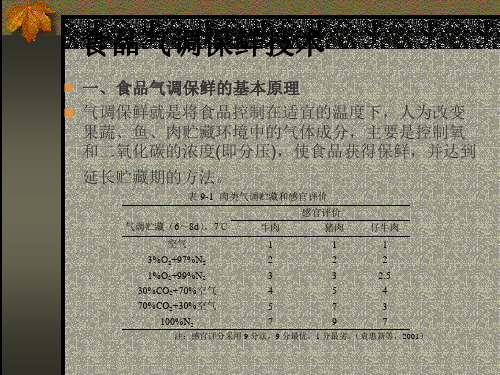
表 9-1 肉类气调贮藏和感官评价
气调贮藏(6~8d),7℃
牛肉
感官评价 猪肉
仔牛肉
空气
1
1
1
3%O2+97ห้องสมุดไป่ตู้N2
2
2
2
1%O2+99%N2
3
30%CO2+70%空气
4
70%CO2+30%空气
5
3
2.5
5
4
7
3
100%N2
7
9
7
注:感官评分采用 9 分法,9 分最优,1 分最劣。(袁惠新等,2001)
YAESU FT-817小型天调的制作

YAESU FT-817小型天调的制作来源:《专业无线通信》作者:BD3SE 孙卫东FT-817是一款体积小、耗电省,功能模式全、工作频带宽便于携带,非常适合户外通讯的机型,深受广大HAM的喜爱。
只是它的发射功率实在太小,特别是在短波段只有5W的发射功率,在天线不太匹配的情况下很难取得稳定可靠的通讯效果,为了方便移动和固定通讯使用,笔者参考网上国外的成品资料,制作了一个简易天调,效果不错,外型小巧美观(见图1)。
图1下面介绍一下制作方法:一、准备材料1.天调外壳选用的是日光灯上使用的金属壳电子镇流器外壳。
2.高频M型插头一个,需要在车床上加工一下,就是在M型插头的尾部加工一个丝扣,方便安装(见图2-1)(图2-2)。
图2-1图2-23.M型插座一个。
4.外径30mm左右的高频磁环一个或其他型号大小根据自己的实际情况定。
5.10挡小型波段开关一只。
6.直径0.45mm左右漆包线。
二、安装1.在高频磁环上用漆包线绕22匝,(多绕也可以,根据波段开关来选择)每2匝抽一个头共10个抽头,然后将10个抽头分别焊在小型波段开关上(见图3)。
图32.按(图4-1)和(图4-2)的方法把元件焊接安装进机壳内。
图4-1图4-2 3.装配好的样子(见图5)。
图5三、实验1.将装配好的天调用万用表测量无误后,就可以按(图6)的样子安装到FT-817的后面了,然后接上所工作波段的天线,将FT-817的功率放置在2挡,对着话筒喊话的同时看FT-817的SWR条码指示,如果SWR指示有条码,就调整波段开关使SWR条码指示消失或最小,然后换全功率用同样的方法调试就可以使用了。
图62.也可以使用拉杆天线,有一种中间有加感线圈的拉杆天线,长度大约在2米以上通过调整天调以后可以工作在15m波和10m波或6m波。
3.建议最好使用单波段天线,也就是说FT-817工作在哪个波段就使用哪个波段的天线。
手动天调使用说明

工作频
本“手动天调”集:功率驻波比表、天线调谐器于一体,无需另配价当选择不接入天调,直通时线调谐器部分不工作。
利用此功能,可对进行调谐前应将电台置于“CW”模式,将电台的发射功率调整至较小将有可能造成发射机的损坏。
任何天调的阻抗匹范围都是有限的,若超出这一范围值时,将不能进快速粗调简易操作方法:
确认“天调”与天线以及电台之间的连接可靠。
将电台的工作模式置某一档位(此档位即可定为基本谐振点使用),分别调整“调容一”、“发射功率大小后,再进行精细调整。
将驻波比调整到小于1:2以下时,将电台工作的模式调整至希望工作请勿在机壳打开时进行发射,否则将会对人体产生近距离辐射!
使用本天调时,射频功率应限制在200W以内!(有朋友用到700W没
体积:24.8X25X10cm,小于FT-80C
重量:2.5公斤
从左向右偏转的表针指示的是正向功率,从右向左偏转的表针指示的以下是制作者刘老师的信息:
姓名:刘向林 ; 呼号:BG4IIJ ; 地址:山东省平度市红旗路197号94112 ; 工行卡号:621226 3803006 994804; 支付宝账号:bg4iij@163.。
气调贮藏技术简介精选全文完整版

可编辑修改精选全文完整版气调贮藏技术简介1. 气调贮藏发展现状气调贮藏可以说是继发明机械冷藏以后果蔬贮藏技术的又一重大革新。
四十年代美国开始兴建气调冷藏库用于商贮苹果,获得明显效益。
五十年代以后,气调贮藏技术有了世界范围的发展,成为当今先进而又成熟的果蔬商贮技术。
七十年代,气调贮藏技术在发达国家就已经得到了广泛的应用。
目前西欧国家建造的果蔬贮藏库有95%以上是气调库。
在气调与冷藏的果品总量中,气调贮藏在意大利超过了50%,美国占50%,法国及德国占40%。
阿根廷、智利、巴西、新西兰、澳大利亚、南非等国家也通过发展气调贮藏,建造大型气调库,使贮藏质量大大提高,赢得了国外市场,获取了巨大的经济效益,在过去十年中,这些国家果蔬出口方面取得了丰硕的成果。
80年代中期至90年代初,我国开始兴建气调库,发展机械气调贮藏。
但是由于当时我国在气调库设计、建造,气调设备研制生产方面尚无成熟经验,总体技术水平还较低,气调库使用中缺乏经验,适宜气调贮藏的高品质果蔬较少,气调水果市场需求量也少,这一时期所建造的气调库大部分没有真正利用起来,没有体现其自身价值,产生应有效益,这为气调库的后来发展罩上了阴影。
一直到现在,仍然有一部分人甚至少数专家认为机械气调在中国不可行,应该继续发展小包装贮藏。
然而机械气调贮藏技术在世界范围内毕竟是非常成熟又广泛应用的保鲜新技术,我国初期发展虽然遇到了暂时困难,但到了90年代中后期,时机条件均已成熟,该项技术又蓬勃发展起来。
这一时期,在许多果蔬产地如在山东胶东又新建了部分气调库,而且得到了很好的利用,既提高了果蔬贮藏质量,又产生了很好的经济、社会效益,初步体现了机械气调发展的良好前景。
最近几年,山东省每年改建及新建气调库约3万吨,发展十分迅速。
许多恒温库也正在计划发展机械气调。
2、气调技术的优越性大多数企业,对气调贮藏的优越性可能略知一二,因为许多人实际已经应用过该项技术,如蒜薹、猕猴桃的保鲜袋MA贮藏。
工尺谱简易教程
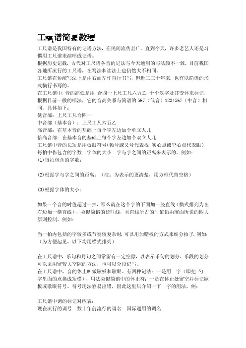
工尺谱简易教程工尺谱是我国特有的记谱方法,在民间流传甚广。
直到今天,许多老艺人还是习惯用工尺谱来演唱或记谱。
根据历史记载,古代对工尺谱各音的记法与今天通用的写法颇不一致。
目前我国各地所流行的工尺谱,在写法和读法上也仍然大不相同。
工尺谱在传统写法上是由右而左作直行书写,但近二三十年来,也有以简谱的形式横行书写的。
在工尺谱中,音的高低是用"合四一上尺工凡六五乙"十个汉字及其变体来标记,根据目前一般的唱法,它的音高关系与简谱的567(低音)1234567(中音)相同。
具体如下:低音部:上尺工凡合四一中音部(基本音):上尺工凡六五乙高音部:在基本音的基础上每个字左边加个单立人儿倍高音部:在基本音的基础上每个字左边加个双立人儿工尺谱中音的长短是用板眼符号(顿号或叉号代表板,实心点或空心点代表眼)、每拍中作包含的字数、字体的大小、字与字之间的距离来表示的。
例如:(1)每拍包含的字数:(2)根据字与字之间的距离:(注:为表示的更清楚,用方框代替空格)(3)根据字体的大小:如果一个音的时值超过一拍,那么就在这个字的下面加一竖直线(横式排列为在右边加一横直线),类似简谱的延时线,且直线所占的时值仍由前面所说的四大原则控制。
例如:当一拍内包括的字较多或节奏较复杂时,可以用加赠板的方式来细分拍子。
例如:(为方便起见,以下均用横式排列)在工尺谱中,乐句和月句之间常留有一定空隙,以表示乐句的划分。
乐段的划分可以采用留较大空隙的方法,也可以分段记写。
在工尺谱中,音的休止叫做歇板和歇眼。
有两种记法:一是用""字(即把"勺"字里面的点换成短横),用法类似简谱中的休止符;一是在休止处留空并标记歇板或歇眼符号。
符号用法容易出错,因此这里只介绍一下""字的用法。
例:工尺谱中调的标记对应表:现在流行的调号数十年前流行的调名国际通用的调名小工调小工调(乙字调) D大调乙字调凡字调 A大调凡字调上字调降E大调上字调六字调降B大调六字调尺字调 F大调尺字调四字调(五字调) C大调正宫调(五字调)正宫调 G大调工尺谱中的强弱记号、反复记号、表情记号、速度记号等,都是用文字来标记的,记在工尺音字的左侧、板眼符号的右侧或工尺音字的行间。
- 1、下载文档前请自行甄别文档内容的完整性,平台不提供额外的编辑、内容补充、找答案等附加服务。
- 2、"仅部分预览"的文档,不可在线预览部分如存在完整性等问题,可反馈申请退款(可完整预览的文档不适用该条件!)。
- 3、如文档侵犯您的权益,请联系客服反馈,我们会尽快为您处理(人工客服工作时间:9:00-18:30)。
Hendricks 40m – 15m SOTA Halfwave TunerFirst, familiarize yourself with the parts and check for all the components. Parts Inventory1 - Tayloe SWR Indicator kit1 - T50-6 core (yellow)1 – poly-varicon, w/shaft and mounting hardware24” - magnet wire for the toroid2 – 6-32 x 5/8” Philips pan head screw2 - #6 s.s lock washer2 - #6 s.s. flat washer2 - 6-32 s.s. wingnut2 - #6 nylon step washer2 - #8 nylon flat washer2 - #6 tinned solder lug2 - 6-32 s.s. nut2 - 4-40 x 1/4" undercut flat head screw1 - bnc female, chassis mount1 - 1/4" shaft knob18” - 22 AWG hook-up wire1 - chassis1 - decal setBegin by assembling the Tayloe SWR Indicator Kit. Dan’s complete assembly instructions are located in the appendix of this document or on-line at /files/LED SWR 20v1.pdf .The last component to solder to the Tayloe SWR board is the LED. Use the above dimensions to locate the lip of the LED, and adjust the inside nut of the switch, for the correct fit to the chassis. Then, set the SWR indicator aside, for now.The rest of the assembly is done inside the chassis. So, now you need to prepare the chassis with the decals.The decals are applied the same as model decals. Cut around each group of text or symbols you wish to apply. It doesn’t have to be perfect as the background film is transparent. Apply the decals before you mount anything to the chassis. Use the above picture to get the correct spacing around the holes, as it is very easy to do a great decal installation and have a portion covered up with a knob. Thoroughly clean the surface of the panel to remove any oils or contamination. If you do not paint your case, we have found that moving the decals into position on a bare aluminum chassis is more difficult, due to the brushed surface, so we advise pre-coating the chassis with the Krylon clear before applying the decals.Trim around the decal. After trimming, place the decal in a bowl of lukewarm water, with a small drop of dish soap to reduce the surface tension, for 10-15 seconds. Using tweezers, handle carefully to avoid tearing. Start to slide the decal off to the side of the backing paper, and place the unsupported edge of the decal close to the final location. Hold the edge of the decal against the panel, with your finger, and slide the paper out from under the decal. You can slide the decal around to the right position, as it will float slightly on the film of water. Use a knife point or something sharp to do this. When in position, hold the edge of the decal with your finger and gently squeegee excess water out from under the decal with a tissue or paper towel. Work from the center, to both sides. Remove any bubbles by blotting or wiping gently to the sides. Do this for each decal, and take your time. Allow to set overnight, or speed drying by placing near a fan for a few of hours. When dry, spray two light coats of matte finish, Krylon, clear to seal and protect the decals, and allow to dry in between coats. All decals come with two complete sets, in case you mess one up.Allow plenty of time for the clear spray to harden up, and continue as follows:•Using the above details, assemble the two antenna connections and the bnc connector to the chassis cover. The nylon step washers keep the antenna connections insulated from the aluminum chassis. Position the solder tabs as shown, and angled down slightly, so that the antenna lug does not short against the PEM nut when the case is assembled.Check to see that there is no continuity between the lugs and the case.•Wind L1, using the T50-6 yellow toroid, and the enclosed magnet wire, with 28 turns total, and a tap at 4 turns from the “START” end. Remember, every time the wire passes through the center of the toroid, counts as one turn.•Pre-wire the Poly-varicon as shown with 2” pieces of the hook-up wire. This puts the two sections of the poly-varicon in parallel. At this time, adjust the small trimmers on the back of the poly-varicon for half engagement.•Put a small piece of electrical tape on the back of the poly-varicon. This will act as a surface to secure the toroid. Wire the toroid to the poly-varicon as shown, and secure it with a couple of drops of hotmelt glue or suitable adhesive. Mount the shaft and center screw provided.•Pre-wire the Tayloe SWR indicator as shown with 3” long pieces of hook-up wire.•Install the pre-wired Tayloe SWR indicator as shown, and secure it to the chassis with the remaining toggle switch nut.•Study the above picture carefully to complete the final interconnections.1. Mount the poly-varicon/toroid assembly to the chassis cover, with the two2.6mm screws.2. Solder the wire from center connection of the poly-varicon to the counterpoise lug.3. Solder the wire from the side connection of the poly-varicon to the antenna lug.4. Solder the “ANT” wire from the swr indicator to the toroid tap.5. Solder the “TX” wire from the swr indicator center connection of the BNC connector.6. Solder the “GND” wire from the swr indicator to the BNC ground lug.Before proceeding test with the toggle switch in the “OPERATE” position, there should be no continuity between the wingnuts and the case.7. Now, solder a wire from the BNC ground lug to the counterpoise ground lug.8. Fit the bottom half of the case to the top and secure it with the two flat head 4-40 screws.9. Install the knob on the poly-varicon shaftPrint out the above label, and scale if necessary to fit the bottom of the chassis. Cover it with a pieceof clear packaging tape, and attach it with two-sided tape.Using your Hendricks SOTA Halfwave TunerUse some light weight wire and start with the lengths suggested, for the band you wish to operate. How the wire is configured depends greatly what you have to work with in terms of support trees and structures. The simplest configuration is an inverted “V”, where the active element runs from the antenna connection of the tuner, up to a tree branch, and back down towards the ground. An “L” configuration for the active element is somewhat better for DX, especially if you can get the part of the wire from the tuner up to the tree as vertical as possible. If the wire is run fairly close to the ground, it favors close in contacts. Try to keep the counterpoise 180 degrees from the active element.Schematicsota_assembly_100511.pdfN7VE LED SWR BridgeHendricks QRP KitsA simple, rugged and lightweight SWR bridgeby Dan Tayloe, N7VETable of ContentsKit Parts (3)Building the LED SWR bridge (3)RF step up transformer (4)Other top mounted parts (6)Bottom mounted parts (7)DPDT Switch mounted (8)Mounting the board to a case (9)Attaching the switch to the case (9)Initial DC tests (10)Initial RF tests (10)Usage – Caution! QRP power only! ~ 5w max! (10)List of FiguresFigure 1. Kit bag of parts right out of the box (3)Figure 2. Contents of the bag identified (3)Figure 3. FT37-43 RF step up transformer with first 5 turns. Make loop for 5T tap (4)Figure 4. 25 turns total totally fills the core (4)Figure 5. Close up view of the RF step up transformer with dressed leads (5)Figure 6. RF step up transformer mounted on the PCB (5)Figure 7. Double check after mounting that the inductor is mounted properly (6)Figure 8. Mounting D1, R4, and C1. Note the position and band orientation of the mounted D1 (6)Figure 9. Pre-form the leads of thethree 51 ohm resistors as shown (7)Figure 10. Three 51 ohm power resistors mounted on the bottom side of the PC board (7)Figure 11. Switch shown mounted on the top side (8)Figure 12. Switch mounted to simulated front panel. LED not soldered yet (9)Figure 13. LED mounted and soldered to PCB (9)Kit PartsFigure 1. Kit bag of parts right out of the boxFigure 2. Contents of the bag identifiedBuilding the LED SWR bridgeNote: Order is important: LED last; Switch next to last, 51 ohm power resistors just before that.Note: This bridge is for QRP only! 5w average power (10w PEP) max!RF step up transformerFigure 3. FT37-43 RF step up transformer with first 5 turns. Make loop for 5T tap.Figure 4. 25 turns total totally fills the core.After winding the RF step up transformer as above, clip one side of the 5T tap loop. Next trim the leads as shown below:Figure 5. Close up view of the RF step up transformer with dressed leadsAfter dressing the leads as above, take an ohm-meter, place it across the “start” and “end” leads above, and make sure that the ohm-meter shows a short (0 ohms). If this is not the case, the twisted leads at the 5T tap have not been properly soldered together.Figure 6. RF step up transformer mounted on the PCBFigure 7. Double check after mounting that the inductor is mounted properly. These pads must be shorted!Using a ohm-meter check the three pads above to make sure that all of these pads show a short to each other. This makes sure that the RF step up transformer has been constructed and mounted properly.Other top mounted partsFigure 8. Mounting D1, R4, and C1. Note the position and band orientation of the mounted D1C1 has some crimps that I straightened out in order to mount it more flush to the top of the board asshown. R4 gets mounted now alsoMake very, very sure diode D1 is mounted as shown above. D1 is mounted on end, with the band oriented up as shown.The LED does not get mounted until the very last step! Do not mount the switch yet! Bottom mounted partsFigure 9. Pre-form the leads of the three 51 ohm resistors as shownFigure 10. Three 51 ohm power resistors mounted on the bottom side of the PC boardDPDT Switch mountedFigure 11. Switch shown mounted on the top side.It is a bit hard to keep the switch flat while soldering it down. I suggest soldering down one corner, making sure the switch is flat, then soldering the opposite corner, and double checking the switch is indeed flat and level before finally soldering it down.Do not despair if you don’t get the switch completely level. It affects nothing but aesthetics as the board mounts using the switch hardware.Note the LED is not mounted yet.Mounting the board to a caseAttaching the switch to the caseFigure 12. Switch mounted to simulated front panel. LED not soldered yet.Figure 13. LED mounted and soldered to PCB.The LED shown here is larger than that actually supplied. I personally like the smaller one better. I drilled LED the hole slightly smaller than the LED, then gradually enlarged the LED hole by spinning a tapered file in it until I got a snug press fit of the LED in its hole. Alternative epoxy could be used.Initial DC testsPlace an ohm-meter across the terminals market “TX”. With the toggle handle away from the LED (as shown in the figure above), the ohm-meter should show 75 ohms. In this position, the SWR bridge is in the circuit, allowing SWR readings to be taken.Place an ohm-meter across the terminals market “TX”. With the toggle handle towards from the LED (as shown in the figure above), the ohm-meter should show an open circuit. In this position, the SWR bridge is out the circuit. This is the “operate” position that is used after the antenna has been tuned for best SWR.Place an ohm-meter across the terminals market “ANT”. With the toggle handle away from the LED (as shown in the figure above), the ohm-meter should show 51 ohms.Place an ohm-meter across the terminals market “ANT”. With the toggle handle towards from the LED (as shown in the figure above), the ohm-meter should show an open circuit.Initial RF testsThis test makes sure that both the diode D1 and the LED have been installed with the same polarity. If one of these were to be installed backwards, the LED will never light.Connect a QRP transmitter (5w max!) to the TX terminal. Leave the antenna connection open. Make sure the switch is positioned away from the LED (SWR bridge is in the circuit). Send a single “dit” on the QRP transmitter and make sure the LED lights up. No antenna is a worst case SWR situation. Optionally, a 50 ohm load can be connected to the antenna side, and another single ‘dit’ and make sure the LED is either out or very dim.Usage – Caution! QRP power only! ~ 5w max!An LED SWR bridge is almost always used with an antenna tuner. When tuning up an antenna using an antenna tuner, first listen to the band background noise on the receiver, and try to peak the band noise using the tuner controls. This should get the tuner in the ball park.Next place the LED SWR bridge into the circuit by placing the switch away from the LED. I suggest tuning up by sending a series of dots. A series of dots will keep your transmitter PA finals from overheating, as well as pulsing the LED on. Now adust the tuner to get the minimum LED brightness. Even a dim LED is a very good SWR level. The normal situation is to adjust the tuner until the LED goes out. This indicates a very good match.After the antenna is tuned up, switch the bridge out of the circuit by flipping the switch handle towards the LED. Keeping the bridge in the circuit will reduce the power by a factor of four to a matched antenna. This can occasionally be useful when trying to bring a 3w QRP transmitter to under the 1w level for certain sub-one watt contest multipliers.。