Electrochemical supercapacitors for energy storage and delivery
电吸附的英文的文献综述

Capacitive Deionization with carbon nanotubes electrodes as an electrochemical means of saving energy and delivering clean water. Abstract:In the 21st century, nanotechnology has been proven to be a new solution to mitigate the the word,s energy crisis and environment contamination problems.Electrochemical properties of carbon nanotubes have shown unique applications in the fields of energy storage system and water purification.Carbon nanotubes have high conductivity, large surface area and optimal pore size distribution,and have been proposed as electrodes for supercapacitors.on the other hand,the electrochemical capacitor properties of carbon nanotubes make it possible for water purification by capacitive deionization(CDI). Capacitive deionization is a water purification technology with low cost,energy saving,simple and easy operating, It,s shown to be crucial significance for the prevention of water pollution,safeguard of people health and continual economy development.Key word:carbon nanotubes electrodes,Capacitive Deionization , CDI Introduction:The removal of dissolved inorganic contaminants such as metal ions from aqueous solutions is of great importance in environmental processes. Compared with conventional deionization technologies such as evaporation, reverse osmosis,and electrodialysis, electrosorption has been shown to be more efficient and energy saving water purification technology since it is conducted at ambient conditions and low voltages (e.g. 1 V) with no secondary waste and requires no high-pressure pumps, membranes, distillation columns, or thermal heaters [1-10].In the electrosorption process ionic species are removed from aqueous solutions by the imposed electric field via electrostatic attraction within the electrode electrolyte interface.Carbon materials of porous structure constitute very attractive electrodes for CDI processes because of their high specific surface area and their good electrical conductivity[12]. Activated carbons (ACs) are the electrode materials that are used most frequently in CDI, but have several intrinsic disadvantages, such as low conductivity and irregular pore structures that result in limited electrosorption capacity. Thus, the most effective way to improve CDI performance is to develop new electrode materials with high conductivity and regular pore structures,such as Carbon nanotube (CNTs), due to their high ratio of surface area to volume and other outstanding properties, are suitable to be used as electrodes for CDI, which has been described in our previous studies [13]..Text:1.BackgroundElectrodialysis is the closest cousin of capacitive deionization systems and has been successfully used for the desalination of brackish waters. Due to its similarity to CDI processes, it is instructive to examine this technology from two perspectives. Firstly, it is a commercially accepted technology for water treatment. Secondly,there are commonalities between CDI and electrodialysis processes particularly with respect to ion transport in solution as well as through membranes that are worth noting and comparing.A critical review of electrodialysis separation technologies was written by Xu and Huang in 2008 [14]. In addition, Davis has written an excellent chapter concerning the electrodialysis process in Handbook of Industrial Membrane Technology[15] .2.CDI historyA recent review of the CDI process directed specifically to the desalination community has been presented by Oren [16]. In this article, all of the fundamental aspects concerning the electro-adsorption process were exposed and therefore will not be examined in detail here. Historically, CDI dates back to the pioneering electrochemical demineralization work of the Caudle and Johnson groups in the late 1960s and early 1970s [17-19]. Oren also worked on his own version of CDI, which he referred to as electrochemical parameter pumping [20,21]. During the late 1970s until the mid-1980s, Oren was the single largest advocate of the CDI process publishing papers on new carbon materials as well as fundamental electrochemical double layer aspects of electrodes[22-26]. However, a renewed interest in the CDI concept came in the mid-1990s when Farmer et al.[27-29]at Lawrence Liver more National Labs (LLNL), working on high surface area conducting carbon aerogels, developed their own version of a CDI device. The crucial aspect of these new materials was their large increase in surface area. As already stated, capacitance scales with surface area(); thus high surface area carbon materials used as electrodes improve capacitance and have better performance with respect to electro-sorption. These high surface area materials have been essential in the development of both CDI devices and also electrical double layer (EDL) capacitors (sometimes called super or ultracapacitors). Both processes (EDL capacitors and CDI systems) operate in an identical fashion by adsorbing ions at a charged interface.Therefore, these aerogels and other similar high surface area conducting carbon materials can be used in both devices.3.The electrodialysis processElectrodialysis involves moving ions in a potential field across polymeric anion and cation-exchange membranes.Cation- and anion-exchange membranes are placed alternatively between the cathode and the anode. When a potential difference is applied between both electrodes, the cations are drawn towards the cathode (negative electrode) and anions towards the anode (positive electrode). The cations migrate through the cation-exchange membranes, but are retained by the anion-exchange membranes. The opposite occurs with the anions that migrate through the anion-exchange membranes but not through the cation-exchange membranes. This movement produces a rise in the concentration of ions in some compartments (brinestreams) and the decrease in the adjacent ones (dilute streams), from which purified water exits. As a result of the anion and cation migration, electric current flows between the cathode and anode with equal charge equivalents transferred so that charge balance is maintained in each stream.4.the material of CDIMost studies related to CDI have focused on the preparation of electrodes in order to increase capacitance. Various carbon materials with a high specific surface area and good conductivity have been used to produce electrodes for CDI. High-performance carbon electrodes have been developed with materials such as carbon cloth, carbon nanotubes, and carbon aerogels [30-36].So ,the material of the electrode is very important .In this work ,we use carbon nanotube due to its high conductivity,large surface area and optimal pore distribution.It has high efficient in deionization.Carbon Nanotubes(CNTs) have the character of optimum pore size,high surface area and low electrical resistivity. As a typical representative of nanomaterial, they have drawn widespread application in the field of hydrogen storage, quantum nanowires,catalyst supports and energy storage,quantum nanowires,catalyst supports and energy storges(eg.supercapacitor),ect.5. DevelopmentAlthough it is still in its infancy, electrosorptiod deionization is a new desalination technology which has been proposed recently to lower water treatment cost and prevent environmental pollution[37,38]. It is energy-efficient and environmentally friendly since it is operated at low DC voltages without high-pressure pumps, thermal heaters, high direct current voltage, or chemicals.This process removes inorganic ions by charge eparation[39]. An aqueous solution containing dissolved inorganic salts passes between matching pairs of activated carbon electrodes on which electric potential is applied. Inorganic ions are held at the charged electrode surfaces and removed from aqueous solution. After the electrodes become saturated with ions, they are regenerated by releasing the absorbed ions into the purge stream through the reversed potential.It would seem that a lot more research and work are needed for its commercialization in thepresent state. Even though it requires low energy consumption, its capital cost is higher than other technologies due to a high production cost of the module. The module mainly consists of electrodes,spacers, and current collectors. The cost of the electrode manufacture is the highest among the module elements. Accordingly, if this technology can be applied to desalination field cost-effectively,it is essential to develop a carbon electrode that has a reasonable price and high ion adsorption Capacity.Conclusions:The CDI technology is young and needs testing. As Oren[40] reminds us, there are only a few companies trying to commercialize this technology. While some results ofthese early commercialization stories seem to look promising, no information can be obtained on the length of field-testing, or how the electrodes behaved after longer periods of operation. More work remains, however, we should remember the pioneering work of Loeb and Sourirajan on RO membranes[41] .Their work on new materials made presentday reverse osmosis of seawater possible. Perhaps new electrode materials and better process control strategies will make this true for CDI. One hopes that we can recover our water resources and save energy as well.References:[1] Welgemoed, T.J.; Schutte, C.F. Capacitive deionization technology:An alternative desalination solution. Desalination, 2005, 183,327-340.[2] Yang, C.M.; Choi, W.H.; Na, B.K.; Cho, B.W.; Cho, W.I.Capacitive deionization of NaCl solution with carbon aerogelsilicagel composite electrodes capacitive. Desalination, 2005, 174,125-133.[3] Farmer, J.C.; Fix, D.V.; Mack, G.V.; Pekala, R.W.; Poco, J.F.Capacitive deionization of NaCl and NaNO3 solutions with carbon aerogel electrodes. J. Electrochem. Soc., 1996, 143, 159-169.[4] Han, Y.; Quan, X.; Chen, S.; Wang, S.; Zhang, Y. Electrochemical enhancement of adsorption capacity of activated carbon fibers and their surface physicochemical characterizations. Electrochim. Acta,2007, 52, 3075-3081.[5] Pekala, R.W.; Farmer, J.C.; Alviso, C.T.; Tan, T.D.; Mayer, S.T.;Miller, I.M.; Dunn,B. Carbon aerogels for electrochemical applications.J. Non-Cryst. Solids, 1998, 225, 74-80.[6] Gabelich, C.J.; Tran, T.D.; Suffet, I.H. Electrosorption of inorganic salts from aqueous solution using carbon aerogels. Environ. Sci.Technol., 2002, 36, 3010-3019.[7] Yang, K.L.; Ying, T.Y.; Yiacoumi, S.; Tsouris, C.; Vittoratos, E.S.Electrosorption of ions from aqueous solutions by carbon aerogel:An electrical double-layer model. Langmuir, 2001, 17, 1961-1969.[8] Ying, T.Y.; Yang, K.L.; Yiacoumi, S.; Tsouris, C. Electrosorption of ions from aqueous solutions by nanostructured carbon aerogel. J. Colloid Interf. Sci., 2002, 250, 18-27.[9] Ryoo, M.W.; Kim, J.H.; Seo, G. Role of titania incorporated on activated carbon cloth for capacitive deionization of NaCl solution.J Colloid Interf. Sci., 2003, 264, 414-419.[10] Ryoo, M.W.; Seo, G. Improvement in capacitive deionization function of activated carbon cloth by titania modification. Water Res.,2003, 37, 1527-1534.[11].(Pekala et al., 1998)[12].(Qu and Shi, 1998),[13].Wang et al., 2006; Gao et al., 2007).[14] L. Zou, L. Li, H. Song, G. Morris, Water Res. 42 (2008) 2340–2348.[15] J.B. Lee, K.K. Park, S.W. Yoon, P.Y. Park, K.I. Park, C.W. Lee, Desalination 237 (2009)155–161.[16] Y. Oren, Desalination 228 (2008) 10.[17] D.D. Caudle, T.H. Tucker, J.L. Cooper, B.B. Arnold, A. Papastamataki, Research Report Oklahoma University Research Institute, 1966.[18] A.M. Johnson, J. Newman, J. Electrochem. Soc. 118 (1971) 510.[19] A.M. Johnson, U.S. Patent, 3,755,135 (1973).[20] Y. Oren, A. Soffer, J. Electrochem. Soc. 124 (1977) C121.[21] Y. Oren, A. Soffer, J. Electrochem. Soc. 125 (1978) 869.[22] Y. Oren, A. Soffer, J. Electroanal. Chem. 206 (1986) 101.[23] Y. Oren, A. Soffer, J. Electrochem. Soc. 126 (1979) C330.[24] Y. Oren, H. Tobias, A. Soffer, Bioelectrochem. Bioenerg. 11 (1983) 347.[25] Y. Oren, H. Tobias, A. Soffer, J. Electroanal. Chem. 162 (1984) 87.[26] Y. Oren, A. Soffer, J. Electroanal. Chem. 186 (1985) 63.[27] J. Farmer, D. Fix, G. Mack, R. Pekala, J. Poco, J. Appl. Electrochem. 26 (1996) 1007.[28] J.C. Farmer, D.V. Fix, G.V. Mack, R.W. Pekala, J.F. Poco, J. Electrochem. Soc. 143(1996) 159.[29 J.C. Farmer, S.M. Bahowick, J.E. Harrar, D.V. Fix, R.E. Martinelli, A.K. Vu, K.L.[30] P.M. Biesheuvel, J. Colloid Interface Sci. 332 (2009) 258.[31] K.S. Spiegler, Y.M. El-Sayed, Desalination 134 (2001) 109.[32] I.C. Karagiannis, P.G. Soldatos, Desalination 223 (2008) 448.[33] T. Xu, C. Huang, AlChE J. 54 (2008) 3147.[34] T.A. Davis, in: M.C. Porter (Ed.), Handbook of Industrial Membrane Technology,Noyes, Park Ridge, NJ, 1990.[35] K.S. Spiegler, D.K. Laird, Principles of Desalination, 2nd ed., Academic Press,New York, 1980.[36 J.M. Ortiz, J.A. Sotoca, E. Expósito, F. Gallud, V. García-García, V. Montiel,A.Aldaz, J. Membr. Sci. 252 (2005) 65.[37] M.D. Andelman, The flow through capacitor: a new tool in wastewater purification. Filtr. Separat., 35(1998) 345–348.[38] K.S. Spiegler and Y.M. El-Sayed, The energetics of desalination processes. Desalination, 134 (2001)109–128.[39] J.C. Farmer, D.V. Fix, G.V. Mack, R.W. Pekala andJ.F. Poco, Capacitive deionization of NH4ClO4 solutions with carbon aerogel electrodes. J. Appl. Electrochem.,26 (1996) 1007–1018.[40] Y. Oren, Desalination 228 (2008) 10.[41] S. Loeb, S. Sourirajan, U.S. Patent 3,133,132 (1964).。
高温退火五氧化二铌晶体的电化学性能与其在锂离子电池中的应用

高温退火五氧化二铌晶体的电化学性能与其在锂离子电池中的应用李鸽【摘要】采用溶胶-凝胶化学制备方法,以酚醛树脂为模板,合成了尺寸为几百纳米至几微米大小的五氧化二铌(Nb2O5)晶体材料.通过比较在不同气氛条件下退火处理的晶体材料的结构、形貌以及电化学性能的不同,发现经氢气退火处理的五氧化二铌晶体材料的导电性有明显提高,与未经氢气退火处理的材料相比,该材料更适用于作锂离子电池阳极材料.【期刊名称】《上海工程技术大学学报》【年(卷),期】2013(027)001【总页数】4页(P56-59)【关键词】溶胶-凝胶;五氧化二铌;锂离子电池【作者】李鸽【作者单位】上海工程技术大学城市轨道交通学院,上海201620【正文语种】中文【中图分类】TQ317.4随着经济的发展,多种电子产品的发明,锂离子电池开始广泛应用于便携电子产品上,如数码相机、笔记本电脑、手机等[1].同时,由于生活水平的不断提高,电子产品朝着微型化、高能量化发展,使得对锂离子电池的储能、寿命等性能条件提出了更高的要求.微电子产品的工作电压已经从3V 降至2.5V,在不远的将来还将降至1.9V 左右[2].根据Kumagai等[2]的报道,五氧化二铌(Nb2O5)是少数的几个充电电压低于2 V的阳极材料.1981年,Reichman等[3]首次将Nb2O5应用于锂离子电池的电极材料.Nb2O5材料具有不同的晶体结构,其充电/放电行为也各不相同.Koshiba等也曾对Nb2O5的不同晶体结构与其电化学行为做过深入研究,发现四方形结构的Nb2O5具有非常好的脱嵌锂离子能力.Nb2O5的理论电容量值约200mA·h/g.相对于Li+/Li,其工作电压平台较低,约1.5V[4-6],故Nb2O5材料被纳入可靠的阳极候选材料之一,但其导电性能较低,电导率σ仅3×10-6 S/cm[7].根据现有的文献资料,有若干种方法来克服Nb2O5材料电导率低的问题,例如,通过在铌电极体系中引入一些导电因素的方法,通过增加碳黑导电剂的比例,可以使电极的倍率性能得到显著提高,但引入碳黑材料后会导致电极电容量值的下降[6].最近,Dunn实验小组[8]报道了多孔Nb2O5薄膜电极的合成,显著提高了Nb2O5电极的倍率性能,但是有限的膜厚度(约200nm)极大限制了其在很多领域的应用.同时,有相关文献报道,尺寸在几百纳米至几微米之间的晶体材料具有最佳的电化学性能.为了增加Nb2O5材料固有的导电性,而不引入其他导电材料,本文采用酚醛树脂作为模板,制作尺寸合适且相对均一的Nb2O5晶体材料,再采用高温热处理的方法来增加Nb2O5材料固有的导电性.1 实验方法及设备1.1 Nb2O5晶体的合成为得到尺寸均一且尺寸分布在几百纳米至几微米的晶体材料,本实验使用酚醛树脂作为模板来辅助Nb2O5晶体颗粒的生长.合成方法如下:将1.0g五氯化铌(NbCl5)粉末,0.333g三嵌段共聚物F127与0.5 mL 37%的浓盐酸共同溶解于10mL乙醇溶液中.将0.5 mL 20%酚醛树脂寡聚体乙醇溶液加入上述溶液中,搅拌2h形成无色透明溶液.将该无色透明溶液转移至玻璃表面皿中静置,至溶剂挥发完全形成凝胶.该凝胶置于140℃条件下保温12h后,置于180℃保温12h,使其进一步聚合.随后,将该凝胶置于马弗炉中在空气条件下煅烧除去碳组分,升温程序为3h内由室温升至530℃,30 min内由530℃升至720℃,并在720℃下保温10h,得到的白色粉末状Nb2O5在900℃下分别由氮气和氢气退火处理4h.样品分别标记为PA-Nb2O5-N2和PA-Nb2O5-H2,两个样品的颜色分别为白色和蓝色.1.2 材料结构的检测与表征材料的晶体结构用X 线衍射仪测得,样品的扫描范围(2θ)为10°~80°.样品颗粒的形貌用扫描电子显微镜(SEM)来观察.1.3 电极材料的组装及电化学性能测试在电极制备中,按照质量比m(活性物质材料)∶m(碳黑)∶m(聚偏二氟乙烯)=81∶1∶1制作电极.按比例取Nb2O5晶体材料、聚偏二氟乙烯(PVDF)和碳黑(Carbon Black),将混合物均匀分散在甲基吡咯烷酮(NMP)中,超声并磁力搅拌使混合的浆状物保持均匀稳定.再将浆状物均匀涂抹在用镍片制成的衬底上形成电极,随后将电极在100℃烘箱中保温8h.电化学性能充放电测试使用仪器LAND CT2000.在氩气条件下的手套箱中组装标准的2032 型纽扣电池.锂箔片既作为对电极又作为参比电极使用.将1 mol/L 六氟磷酸锂(LiPF6)溶于碳酸乙烯酯/二甲基碳酸酯(ED/DMC)(V(ED)∶V(DMC)=1∶1)中,制成锂电池电解液.随后,在不同的电流密度下进行充放电测试电池.2 结果与讨论2.1 材料的晶体结构与形貌不同的合成与处理条件对Nb2O5晶体结构有较大的影响[5].本实验分别考察了在相同温度(900℃)下经氮气、氢气退火样品的晶体结构,如图1所示.通过XRD 图发现,两种样品的谱峰上并未出现明显的杂峰,这表明,在处理过程中,没有分相现象发生.如图1(a)所示,氮气退火的Nb2O5样品具有单斜晶形,与JCPDS卡片单斜晶形Nb2O5完全吻合.而经氢气退火的样品却具有完全不同的晶形,如图1(b)所示,属于正交晶系的Nb2O5,产物呈深蓝色.可以推测,在高温氢气还原过程中,出现了部分还原现象,Nb2O5晶体产生了悬键.据文献报道,部分还原的铌原子可显著提高Nb2O5的导电性.因此,经氢气退火的Nb2O5样品应具有良好的电化学性能.SEM 图像清晰地显示了Nb2O5晶体的形貌特征.如图2所示,通过酚醛树脂模板的辅助合成,氧气条件下预处理除去多余的碳,留下的Nb2O5晶体大小、结构统一,尺寸分布在几百纳米至几个微米之间.而经过进一步的高温处理,晶体进一步生长融合,孔洞逐渐消失,形成了团聚状态,如图3所示.图1 样品PA-Nb2O5-N2与PA-Nb2O5-H2的XRD图Fig.1 XRD pattern of samples PA-Nb2O5-N2and PA-Nb2O5-H2图2 预处理后Nb2O5晶体的低倍率和高倍率SEM 图Fig.2 Low-magnification and high-magnification SEM images of as-synthesized Nb2O5图3 氢气退火处理后Nb2O5晶体的低倍率和高倍率SEM 图Fig.3 Low-magnification and high-magnification SEM images of H2-treated Nb2O5 2.2 材料的电化学表征本实验对高温条件下经氮气与氢气退火后的两个样品进行了电化学性能测试,比较了电极在100圈恒电流充放电过程的循环性能,如图4 所示.选择电流密度为50mA/g,经过氢气处理后的Nb2O5晶体材料的电容量值得到了显著提高,在第一圈时放电容量达到了240 mA·h/g,而氮气处理后的Nb2O5晶体的首圈放电容量仅约为165 mA·h/g,与文献[7]报道相符.实验表明,经过氢气处理后的Nb2O5晶体材料的充放电性能得到了很大提高,氢气对Nb2O5晶体部分的高温退火还原增强了其自身的导电性能.本实验发现,两个样品100圈充放电循环中均出现了电容量缓慢衰减现象.一般来说,纳米或微米级结构的材料由于比表面积的增加,使得电极与电解液的接触界面显著增加,大量形成的固体电解质中间相(SEI)层不仅不断消耗电解液,而且逐步降低材料的电容量值,造成电容量衰减[9-11].图4 样品PA-Nb2O5-N2与PA-Nb2O5-H2的循环性能比较Fig.4 Cycling performance comparison of samples PA-Nb2O5-N2and PA-Nb2O5-H2为了进一步考察氢气高温退火处理后Nb2O5晶体的导电性能,本实验又对PA-Nb2O5-H2样品做了倍率性能测试,见图5.通过不同的电流密度,40、100和200 mA/g测试,Nb2O5材料具有的电容量分别为160、120和80mA·h/g,电容量值始终保持稳定.可以推测,经退火处理后Nb2O5晶体的导电性能得到提高,同时也对提高电极的锂离子扩散速度起着重要的作用.图5 样品PA-Nb2O5-H2的倍率性能Fig.5 Rate capability of PA-Nb2O5-H23 结语通过实验可以发现,在不同气氛下经过高温处理的样品所表现出的电化学性能完全不同.经氮气高温处理后的样品,其电化学性能仍然较差;而经过氢气处理后的样品,电化学性能则大大提高.这说明,经过氢气高温处理后的样品的导电性能增加.这是由于经高温还原后,Nb2O5晶体出现了部分悬键,更有利于电子之间的传递,故在锂离子电池中的应用提高了电极的性能指标,这也为今后的锂离子电池研究提供了一条新思路.参考文献:[1]Conway B E.Electrochemical Supercapacitors;Scientific Fundamentals and Technological Applications[M].New York:Kluwer Academic/Plenum Pblishers,1999:29.[2]Kumagai N,koishiJawa Y,komaba S,et al.Thermodynamics and kinetics of lithium intercalation into Nb2O5electrodes for a 2 Vrechargeable lithium battery[J].J Electrochem Soc,1999,146(9):3203-3210.[3]Reichman B,Bard A J,Electrochronmism at niobium pentoxide electrodes in aqueous and acetonitrile solutions[J].J Electrochem Soc,1980,127(1):241-242.[4]Han J T,Liu D Qi,Song S H,et al.Lithium ion intercalation performance of niobium oxides:KNb5O13and K6Nb10.8O30[J].Chemistry of Materials,2009,21(20):4753-4755.[5]Han J T,Huang Y H,Goodenough J B.New anode framework for rechargeable lithium batteries[J].Chemistry of Materials,2011,23(8):2027-2029.[6]Wei M D,Wei K,Ichihara M,et al.Nb2O5nanobelts:a lithium intercalation host with large capacity and high rate capability[J].Electrochemistry Communications,2008,10(7):980-983.[7]Viet A L,Reddy M V,Jose R,et al.NanostructuredNb2O5polymorphs by electrospinning for rechargeable lithium batteries [J].Journal of Physical Chemistry C,2009,114(1):664-671.[8]Brezesinski K,Wang J,Haetge J,et al.Pseudocapacitivecontributions to charge storage in highly ordered mesoporous group V transition metal oxides with iso-oriented layered nanocrystalline domains [J].Journal of the American Chemical Society,2010,132(20):6982-6990.[9]Wang Y,Lee J Y,Zeng H C.Polycrystalline SnO2nanotubes prepared via infiltration casting of nanocrystallites and their electrochemical application[J].Chemistry of Materials,2005,17(15):3899-3903. [10]Kim M G,Cho J.Reversible and high-capacity nanostructured electrode materials for Li-ion batteries[J].Advanced Functional Materials,2009,19(10):1497-1514.[11]Needham S A,Wang G X,Liu H K.Electrochemical performance of SnSb and Sn/SnSb nanosize powders as anode materials in Li-ion cells [J].Journal of Alloys and Compounds,2005,400(1-2):234-238.。
超级电容器的原理及应用01
Principles and applications of supercapacitors
CHEN Ying-fang, LI Yuan-yuan, DENG Mei-gen
(School of Electronics, Jiangxi University of Finance & Economics,Nanchang 330013 , China) Abstract: As a new kind energy storage device, supercapacitors have characteristics of high power density, extremely large capacitance, long cycle life and high charge-discharge efficiency. For this reason, world wide attention was attracted. The fundamental principles, classification and characteristics of supercapacitors were reviewed, and their main application areas and development trend were introduced. Key words: electron technology; supercapacitors; review; principles; applications
第 27 卷 第 4 期
陈英放等:超级电容器的原理及应用
7
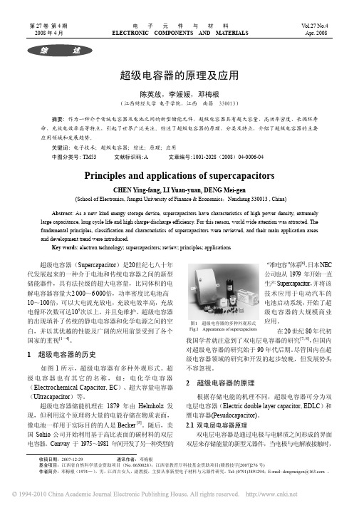
由于库仑力、分子间力、原子间力的作用,使固液界面 出现稳定的、符号相反的双层电荷,称为界面双层。 双电层电容器使用的电极材料多为多孔碳材料, 有活性炭(活性炭粉末、活性炭纤维)、碳气凝胶、 碳纳米管。双电层电容器的容量大小与电极材料的孔 隙率有关。通常,孔隙率越高,电极材料的比表面积 越大,双电层电容也越大。但不是孔隙率越高,电容 器的容量越大。 保持电极材料孔径大小在 2~50 nm 之 间提高孔隙率才能提高材料的有效比表面积,从而提 高双电层电容。
水热碳化法制备碳纳米材料

《纳米材料与纳米技术》论文水热碳化法制备碳纳米材料摘要:水热碳化法是一种重要的碳纳米材料的制备方法,本文综述了近年来以糖类和淀粉等有机物为原料,采用水热碳化法制备各种形貌可控碳纳米材料的研究现状,并提出了该方法研究中存在的问题以及今后可能的发展方向。
关键词:水热碳化法、碳纳米材料、碳微球、碳空心球、核壳结构复合材料1 引言形态可控的碳纳米材料由于独特的结构和性能而受到研究者的普遍关注[1],常见的制备方法有化学气相沉积法(CVD)[2]、乳液法[3]和水热碳化法[4]等。
水热碳化法是指在水热反应釜中,以有机糖类或者碳水化合物为原料,水为反应介质,在一定温度及压力下,经过一系列复杂反应生成碳材料的过程[5]。
图1为水热碳化法所制备的各种形貌的碳材料。
与其他制备方法相比,采用水热碳化法所制备的纳米碳材料具有显微结构可调、优良的使用性能、产物粒径小而均匀等特点。
本文综述了水热碳化法制备形态可控碳纳米材料的最新研究进展,概括了工艺因素对碳纳米材料合成过程的影响,最后提出了水热法合成碳纳米材料今后可能的研究方向。
图 1 水热碳化法制备各种形貌碳材料的示意图2 水热碳化法制备碳微球碳微球由于具有大的比表面积、高的堆积密度以及良好的稳定性等,被应用于锂离子电池[6]、催化剂载体[7]、化学模板[8]、高强度碳材料[9]等方面,拥有广阔的应用前景。
Yuan等[10]以蔗糖为碳源,先采用水热碳化法合成碳微球,再使用熔融的氢氧化钾溶液对合成产物进行活化处理,制得粒径为100-150nm的碳微球。
研究表明活化后碳微球的石墨化程度有很大提高,且表现出良好的电化学性能。
其比容量达到382F/g,单位面积电容达到19.2μF/cm2,单位体积容量达到383F/cm。
Liu等[11]以琼脂糖为原料,采用水热碳化制备出粒径范围为100~1400nm的碳微球,研究结果表明碳微球的粒径随琼脂糖的浓度的增加而增大,且所制备的碳微球的表面富含大量的含氧官能团,这些官能团可以很好地吸附金属离子或者其它有机物等,因此该材料在生物化学、药物传输以及催化剂载体等方面具有很好的应用前景。
超级电容器用MOFs衍生纳米电极材料的研究进展

第52卷第11期2023年11月人㊀工㊀晶㊀体㊀学㊀报JOURNAL OF SYNTHETIC CRYSTALS Vol.52㊀No.11November,2023超级电容器用MOFs 衍生纳米电极材料的研究进展郭容男1,李太文1,王㊀栋1,王天汉1,裴㊀琪1,王媛媛2(1.河南农业大学机电工程学院,郑州㊀450002;2.河南农业大学园艺学院,郑州㊀450002)摘要:超级电容器因具有功率密度高㊁充放电速度快和循环寿命长等优点而备受关注,但是较低的能量密度限制了其广泛应用㊂开发新型高效电极材料对改善超级电容器电化学性能至关重要㊂金属有机框架材料(MOFs)具有比表面积大㊁结构孔径可控和活性位点丰富等特点,故在能量转化和储存领域受到了广泛关注㊂但是由于MOFs 的结构稳定性和导电性较差,其作为超级电容器的电极材料时,无法获得满意的电化学性能㊂以MOFs 为前驱体制得的MOFs 衍生物的稳定性和导电性优于原生MOFs,显著提高了超级电容器的电化学性能㊂本文综述了超级电容器用纳米MOFs 衍生碳化物㊁氧化物㊁氢氧化物㊁磷化物㊁硫化物电极材料的研究现状,总结了MOFs 衍生超级电容器电极材料的合成策略,为超级电容器用MOFs 衍生纳米材料的研究提供指导意义㊂关键词:超级电容器;电极材料;MOF;衍生材料;碳材料;策略选择;结构调制中图分类号:TM53;TB332㊀㊀文献标志码:A ㊀㊀文章编号:1000-985X (2023)11-1922-09Research Progress of MOFs-Derived Nano-Electrode Materials for SupercapacitorsGUO Rongnan 1,LI Taiwen 1,WANG Dong 1,WANG Tianhan 1,PEI Qi 1,WANG Yuanyuan 2(1.School of Mechanical and Electrical Engineering,Henan Agricultural University,Zhengzhou 450002,China;2.College of Horticulture,Henan Agricultural University,Zhengzhou 450002,China)Abstract :Supercapacitors have attracted much attention because of their high power density,fast charging /discharging speed,and long cycle life.However,the low energy density restricted their wide application.Developing novel and efficient electrode materials is imperative to improve the electrochemical performance of supercapacitors.Metal-organic frameworks (MOFs)have attracted extensive attention in the field of energy conversion and storage,owing to their large specific surface area,controllable pore size,rich active sites and easy synthesis.Nevertheless,due to the inferior structural stability and low conductivity of MOFs,the electrochemical performance of supercapacitors with MOFs electrode materials is unsatisfactory.MOFs derivatives,prepared from the MOFs precursor,possess excellent structural stability and conductivity,thus prominently improve the electrochemical performance of supercapacitors.This work mainly focuses on the MOFs-derived electrode materials for supercapacitors,including MOFs-derived carbides,oxides,hydroxides,phosphides and sulfides.The synthesis strategies of electrode materials for supercapacitors are discussed,providing guidance for the research of nano-MOFs-derived materials for supercapacitors.Key words :supercapacitor;electrode material;MOF;derivative material;carbon material;strategy selection;structural modulation㊀㊀㊀收稿日期:2023-04-28㊀㊀基金项目:河南省高等学校重点科研项目计划(23A430016);河南省自然科学基金(232300421332);中国科学院战略性先导科技专项(B 类,XDB44000000-6)㊀㊀作者简介:郭容男(1987 ),女,陕西省人,博士,讲师㊂E-mail:guorn@0㊀引㊀㊀言超级电容器因具有功率密度高㊁充放电速度快和循环寿命长等优点而备受关注㊂超级电容器根据储能原理分为电化学双层电容器(electrical double-layer capacitor,EDLC)㊁法拉第赝电容器和混合型超级电容器㊀第11期郭容男等:超级电容器用MOFs衍生纳米电极材料的研究进展1923㊀三类,其充放电机理如图1所示㊂其中,EDLC充电时,通过极化电极吸引电解质中的阴阳离子在电极/电解质界面聚集并形成电势差,使其达到储能要求;法拉第赝电容器则是通过电极在外加电场中极化后,电解质中的阴阳离子被吸引到电极附近,在电极表面发生界面反应,在电极内部和电解质中发生体相反应,界面反应和体相反应使大量的电荷储存在电极上,从而实现储能目的;混合型超级电容器的负极通常以EDLC储能原理储能,正极为法拉第赝电容器,通过氧化还原反应进行储能,从而获得更宽的电势窗口,电化学性能得到提升㊂优异的电极材料可使超级电容器具有出色的功率密度㊁循环性能和能量密度㊂电极材料的优劣主要通过其比表面积㊁孔结构㊁活性位点和导电性进行评判[1]㊂金属有机骨架(metal-organic framworks,MOFs)是一种是由金属离子或金属簇和有机配体通过二价或多价配位键构建的三维结构,由于其具有比表面积高(1000~10000m2/g)和孔分布均匀(5~10nm)等优点[2],被广泛应用于吸附[3]㊁催化[4]与传感[5]等领域㊂但是较差的导电性和结构稳定性,限制了其在超级电容器中的应用㊂为此,研究人员以MOFs作为牺牲模板制得MOFs衍生物,MOFs衍生物作为超级电容器的电极材料时,比原生MOFs具有更优异的电化学性能,这主要得益于MOFs衍生物保留了原生MOFs丰富的孔结构和大的比表面积,同时拥有更稳定的结构和更快的载流子传输速度㊂相比普通的MOFs衍生物,纳米MOFs衍生物具有更为特殊的结构和各组分间的协同作用,其构建的超级电容器可以实现快速㊁稳定和高效的电荷储存[6]㊂本文总结了近年来MOFs衍生的纳米材料在超级电容器电极中的应用,详细阐述了策略选择和结构调制对其孔结构㊁载流子传输动力学㊁电化学性能㊁结构稳定性及机械性能的影响,为超级电容器用MOFs衍生纳米材料的研究提供指导㊂图1㊀超级电容器的分类及其充放电机理示意图[7]Fig.1㊀Classification of supercapacitors and their schematic illustration of charge-discharge mechanism[7]1㊀MOFs衍生纳米碳材料纳米多孔碳材料因其高比表面积㊁良好的导电性被广泛应用到EDLC[7]中(见图1)㊂以MOFs作为牺牲模板制备的纳米多孔碳(nano porous carbons,NPCs)保留了原生MOFs的多孔结构,故NPCs具有有序多孔网络结构,广泛作为超级电容器电极[8]㊂NPCs通常通过高温热解直接碳化获得㊂Zhuang等[9]在氩气气氛下高温碳化MIL-100(Fe)纳米颗粒,获得了具有高度石墨化的中空碳多面体(HCPs)㊂HCPs继承了原生铁基MOF的分级孔隙结构,故离子迁移速率快㊂当电流密度为50A/g时,HCPs超级电容器经过5000次充放电循环后,电容仍保持在较高水平㊂虽然NPCs可以继承原生MOFs的孔结构,但是碳化过程可能导致金属纳米颗粒在微孔为主的多孔结构中扩散和不可逆聚集,影响载流子在电极内部的吸附㊁反应㊁缓冲及通过[10]㊂Shang等[11]通过介孔二氧化硅保护煅烧,获得分散良好的ZIF衍生Co和N掺杂碳纳米框架Co,N-CNF㊂如图2(a)所示,以正硅酸四乙酯和十六烷基三甲基溴化铵(CTAB)作为孔导向剂,将mSiO2壳均匀涂覆在ZIF表面,进行高温热解,最后通过蚀刻去除mSiO2壳㊂mSiO2壳能有效防止Co,N-CNF纳米颗粒聚集和融合,故所得Co,N-CNF纳米结构具有清晰的分级孔结构㊁高比表面积(1170m2/g)和高累积孔体积(1.52m3/g)㊂结构调制赋予Co,N-CNF优越的孔结构和比表面积,保障了载流子在电极内部的活动和快速迁移,使超级电容器表现出优异的电化学1924㊀综合评述人工晶体学报㊀㊀㊀㊀㊀㊀第52卷性能㊂MOFs碳化时的反应温度也至关重要㊂Yao等[12]将Zn基MOF在不同碳化温度(即850㊁950和1050ħ)下进行处理,得到MOF衍生的纳米多孔碳(MOF-NPC,分别表示为MNC850㊁MNC950和MNP1050)㊂研究表明,高温有利于增加纳米多孔碳的石墨化程度和导电性,但过高的温度会导致结构破坏,影响其稳定性和电化学性能(见图2(b)~(d))㊂NPCs材料通常亲水性较差,而N元素的引入有效改善了其在水性电解质中的润湿性㊂同时,N掺杂的NPCs具有更优秀的电催化活性㊂Zhu等[13]以ZIF-67为前驱体,在800ħ下碳化2h获得具有丰富孔结构的Co修饰氮掺杂多孔碳(Co-NPC),再进行磷化得到CoP修饰氮掺杂多孔碳(CoP-NPC)㊂最后将CoP-NPC锚定在还原氧化石墨烯片上获得超级电容器用复合材料(CoP-NPC/RGO)㊂由于CoP-NPC/RGO的3D互连多孔结构,CoP与氮掺杂碳基体之间的协同效应,故制备的超级电容器在1和20A/g的电流密度下,比电容高达466.6和252.0F/g㊂Fang等[14]以尿素为外加氮源,在氮气气氛下热解Zn-bioMOFs,获得了具有手风琴状分层结构的N掺杂类石墨烯碳纳米片(H-NCNs)㊂通过改变尿素用量,调节H-NCNs的氮掺杂程度和孔隙率,提升H-NCNs组装成超级电容器的比电容㊁倍率性能和能量密度㊂图2㊀mSiO2保护煅烧法合成Co,N-CNF过程[11](a)及Zn基MOF不同碳化温度产物MNC850(b)㊁MNC950(c)和MNC1050(d)的SEM照片[12]Fig.2㊀Synthetic procedure of the Co,N-CNF by the mSiO2protected calcination strategy[11]㊀(a)and SEM images ofMNC850(b),MNC950(c)and MNC1050(d)[12]聚合物和表面活性剂等也可调控MOFs衍生NPCs的结构㊂聚合物可作为MOFs衍生纳米多孔碳的结构导向剂和碳源㊂Wang等[15]以聚多巴胺(PDA)为ZIF-8NP的涂层材料,制备中空结构的氮掺杂碳(NC)㊂热解过程中,PDA层为ZIF-8 向外 拉动提供了驱动力,同时ZIF-8体积减小,形成中空结构㊂阴离子表面活性剂(如十二烷基硫酸钠)㊁阳离子表面活性剂(如CTAB)和非离子表面活性剂等也被广泛用于控制MOFs 衍生物的形态和大小[16]㊂SiO2㊁聚合物或表面活性剂在MOFs表面形成壳,诱导MOFs生长为中孔㊁中空㊁蛋黄壳㊁多维中空或多孔结构的MOF衍生纳米多孔碳㊂尽管聚合物和表面活性剂优化了NPCs的结构,提高了NPCs的电化学性能,但这些策略也存在一些问题,例如SiO2辅助策略需要清除模板,步骤繁多㊁条件苛刻;聚合物辅助仅限于一些特定环境中;表面活性剂易引入杂原子等㊂故研究人员通过声化学[17]㊁盐模板[18]和有机化学蚀刻[19]等方法调制MOFs衍生的纳米多孔碳的结构,但是这些策略目前只用于特殊种类的MOFs㊂此外,研究人员还提出了利用零维材料和MOFs复合制备衍生纳米多孔碳,以期进一步提高超级电容器的电化学性能㊂Tang等[20]使用内部支持策略将零维石墨烯量子点(GQD)作为MOFs刚性支架,获得了高效的MOFs衍生纳米碳材料(GMPC)㊂高度结晶的GQD降低了衍生NPCs的缺陷密度,并构建了内部导电网络㊂当GQD和对苯二甲酸的质量比为0.35时,GMPC获得了优异的比表面积和导电率㊂这种多维耦合内㊀第11期郭容男等:超级电容器用MOFs衍生纳米电极材料的研究进展1925㊀部支持策略显著提高了超级电容器的电化学性能㊂表1总结了其他高效MOFs衍生纳米碳材料及其复合材料的结构调制策略,以及调制后的表面形貌和电化学性能,为后续通过结构调制提升电极电化学性能和开发新策略提供帮助㊂表1㊀超级电容器电极材料用部分高效MOFs衍生纳米碳材料Table1㊀Some highly efficient MOF-derived nano-carbon materials for supercapacitor electrodes电极材料形貌制备策略或方法比表面积/(m2㊃g-1)电解液电流密度/(A㊃g-1)比电容/(F㊃g-1) HC-40-4[21]分级纳米结构碳化2837EMIMBF40.5206 Mn@ZnO/CNF[22]多孔十二面体碳化 6mol/L KOH1501Ni/Co-MOF-NPC-2ʒ1[23]空心微球纳米棒碳化1135ʃ272mol/L KOH11214N-NPC-850[24]互联微孔碳化12446mol/L KOH1479UT-CNS[25]超薄纳米片自底向上合成1535.246mol/L KOH0.5347 MOF525-NC1.35[26]立方体碳化和酸化7861mol/L H2SO42425HZC-2M-2h[27]中空十二面体葡萄糖辅助水热7456mol/L KOH0.5220NiO x@NPC[28]立方结构溶剂热15236mol/L KOH1534NGCA[29]蜂窝状干法冷冻和连续高温10856mol/L KOH1244DUT-5-CN[30]二维纳米结构煅烧415.26mol/L KOH0.5100 Zn/Co-MOF-NPC[31]分级多孔结构煅烧和酸洗11376mol/L KOH0.5270Ni-Fe-O/NPC@PCNFs-400[32]四面体纳米棒自模板MOF合成52.953mol/L KOH11419 ZIF-8-NC/rGO[33]碳纳米纸煅烧和酸浸489.36mol/L KOH1280C-S-900[34]三维分层海绵一步热解法1356.36mol/L KOH20226HZ-NPC[35]多面体结构高温碳化约2026mol/L KOH2545 CTAs@NCBs-700(T)[36]纳米棒阵列乙醇原位催化蒸发9051mol/L H2SO41mA/cm2244㊀㊀注:参考文献22㊁24㊁33㊁34的材料采用双电极体系进行电化学性能测试,其余材料测试均采用三电极体系㊂2㊀其他MOFs衍生的纳米材料基于金属氧化物㊁氢氧化物㊁硫化物及磷化物构建的赝电容超级电容器(见图1(b))在充放电过程中主要通过氧化还原反应进行能量储存,故这些材料比NPCs构筑的超级电容器具有更高的能量密度㊂因此研究人员以MOFs为牺牲模板,合成了MOFs衍生的氧化物㊁氢氧化物㊁硫化物和磷化物㊂这些MOFs衍生的纳米材料继承了原生MOFs的有序孔道结构,作为超级电容器的电极材料时,具有更优异的电化学性能㊂其与NPCs组成的非对称超级电容器以及使用单一材料的对称超级电容器相比,拥有更宽的工作电压窗口㊁更高的能量密度以及更优越的循环稳定性[37]㊂Li等[38]向ZIF-67中添加适当比例的钴和镍离子,制备了衍生自双金属咪唑骨架的化合物空心NiCo2O4和片状Co3O4/NiCo2O4,得益于其独特的片状结构以及镍钴两种金属元素的协同作用,Co3O4/NiCo2O4电极在0.5A/g的电流密度下显示出846F/g的高比电容㊂具有丰富活性位点和独特结构的层状双氢氧化物(layered double hydroxides,LDHs)展现出超高理论电容,故LDHs成为混合超级电容器(hybrid supercapacitor,HSC)的理想电极材料之一㊂然而,当一些环境条件发生变化时,离子之间的相互作用增强,导致LDHs团聚,影响了载流子的储存㊁交换和释放[39],影响了LDHs超级电容器的电化学性能㊂为了缓解LDHs的团聚,研究人员利用MOFs和LDHs制得了MOFs衍生的纳米层状氢氧化物(MOFs-LDHs)㊂Zhang等[40]在MOF的分级结构中原位蚀刻/电沉积,构建了界面扩散电极HKUST-1@CoNiLDH(见图3(a))㊂在1A/g的电流密度下,其比电容为297.23mA㊃h/g㊂HKUST-1@CoNiLDH 与活性炭阳极制成的HSC具有相当可观的能量密度和功率密度(39.8W㊃h/kg和799.9W/kg)㊂Hu等[41]使用电化学阴离子交换方法控制MOFs的水解,合成了多孔Ni/Co氢氧化物纳米片㊂电化学阴离子交换后, MOFs纳米片的有机配体可以循环再利用㊂当NiʒCo的摩尔比为7ʒ3时,多孔Ni/Co氢氧化物电极的能量密度和功率密度高达74.7W㊃h/kg和5990.6W/kg,经过8000次充放电循环后仍具有较高电容保持率㊂在电化学阴离子交换方法控制MOFs水解策略中,可循环利用的有机配体降低了电极的制备成本,这种结构调制方法为后续制备成本更低和更环保的电极材料提供了参考㊂除了MOFs衍生的氧化物和LDHs被广泛作为超级电容器电极,MOFs衍生的硫化物也受到了较多的关注㊂MOFs衍生的硫化物比MOFs衍生的氧化物和LDHs的结构更灵活,与过渡金属之间的配位能力更好㊂1926㊀综合评述人工晶体学报㊀㊀㊀㊀㊀㊀第52卷Acharya等[42]采用MOFs介导硫化合成了瘤状Ni-Co-S纳米材料,并将中空和多孔NiMoO4纳米管集成到rGO 涂覆的泡沫镍上,制备了NiMoO4@Ni-Co-S超级电容器电极材料㊂经过硫化和刻蚀后,NiMoO4@Ni-Co-S电极独特的开放框架和管状结构极大缩短了载流子迁移路径,促进了复合电极的法拉第反应速率㊂在2mol/L 的KOH电解质中,1A/g的电流密度下,获得了318mA㊃h/g的高比容量;经过10000次充放电循环后,初始电容保持率仍高达88.87%,展现了其优异的循环性能㊂磷化物自然丰度高㊁环境友好㊁价格低廉㊂MOFs衍生的金属磷化物纳米材料用作超级电容器电极时,由于多组分的协同作用,增强了电极材料的电导率㊁氧化还原反应动力学和循环性能[43]㊂He等[44]通过水热法实现了层状砖堆叠NiCo-MOF组件的局部磷化,制备了由镍/钴MOF(NiCo-MOF)和磷化物(NiCoP)组成的功能异质结构(NiCoP-MOF)㊂NiCoP-MOF中P-O可以有效防止NiCoP晶体在离子储存和交换时被破坏,赋予了NiCoP-MOF极佳的结构稳定性㊂以其制备的超级电容器的比电容㊁能量密度和功率密度远优于NiCo-MOF㊂Chhetri等[45]通过核-壳静电纺丝技术制备了中空碳纳米纤维(HCNF),然后进行连续稳定和碳化㊂在HCNF内外合成了双金属MOF(Ni和Fe基),并通过磷化转化为双金属磷化物(Ni-Fe-P)㊂HCNF独特的高孔隙率和中空通道,极大提升了电解质离子/电子的传输速率㊂故(Ni-Fe)-P-C@HCNFs电极展现出优异的电化学性能㊂图3㊀HKUST-1@CoNiLDH[40](a)和MOF/MXene/NF[46](b)基电极的合成示意图Fig.3㊀Schematic illustration of synthesis process of HKUST-1@CoNiLDH(a)[40]and MOF/MXene/NF(b)based electrodes[46]尽管MOFs衍生的金属氧化物㊁氢氧化物㊁硫化物和磷化物等纳米材料展现出了优异的电化学性能,但是这些衍生物仍存在金属离子与有机配体之间的弱配位键和不稳定性㊁活性位点利用率低以及晶格失配等诸多问题,导致在储能领域的应用受到了诸多限制㊂针对这些问题,研究人员使用不同的合成策略和结构调制方法开发了MOFs衍生的多元材料和复合材料㊂通过不同元素之间的协同作用和更高效的纳米结构来改善电极材料的电化学性能[47]㊂Li等[48]使用电沉积和CVD制备了阵列结构材料㊂在MOF-CVD过程中,树状阵列之间的自由空间有效缓解了体积膨胀,保证了阵列结构的结构完整性和稳定性㊂在20A/g的高电流密度下,比电容高达368F/g;在经过10000次循环后,电容保持率高达95.9%㊂此外,可利用界面工程构建异质纳米结构,调整混合MOFs衍生纳米材料和其他材料形态,提高超级电容器的电化学性能[49]㊂Yang等[46]通过温度控制退火工艺在泡沫镍(NF)(即MOF/MXene/NF)上制备Ni-MOF/V2CTx-MXene-300复合材料㊂随后在不改变晶体结构的情况下,构建了分级多孔纳米棒复合材料㊀第11期郭容男等:超级电容器用MOFs衍生纳米电极材料的研究进展1927㊀的异质结构(见图3(b))㊂其构建的异质结结构与活性炭/NF作为阳极组成的超级电容器的能量密度和功率密度分别为46.3W㊃h/kg和746.8W/kg,循环15000次后,初始容量保持率高达118.1%,这得益于Ni O V键的界面相互作用可以有效地调节组件的电子结构,增强电子传导性和反应性㊂MOFs衍生超级电容器电极材料的合成策略主要包括模板碳化策略㊁表面修饰策略㊁衍生金属化合物策略等㊂在模板碳化策略中,将MOFs直接高温热解或水热处理生成碳骨架,这种方法可以获得具有高比表面积的和多孔结构的碳材料[50]㊂在表面修饰策略中,通过一些化学修饰将纳米颗粒引入到MOFs的表面或内部,改善MOFs的电化学性能和储能性能[51-52]㊂在衍生金属化合物策略中,将MOFs衍生成金属氧化物㊁双层氢氧化物㊁金属磷化物以及金属硫化物,这些金属化合物具有优异的电化学活性,是超级电容器电极极具潜力的材料[53-54]㊂值得注意的是,具体的合成策略可能会根据具体的MOFs材料和应用需求而有所差异,在设计和合成过程中,需要综合考虑材料的电化学性能㊁稳定性和成本等因素㊂结构调制在MOFs衍生超级电容器电极材料的合成过程中也十分重要,其中经结构调制后的MOFs衍生的多元材料和复合材料所展现的电化学性能尤为突出㊂Pathak等[55]通过同轴静电纺丝合成了具有足够柔韧性㊁导电性和高度功能化的含有中空碳纳米纤维(MXHCNF)的MXenes,并在MXHCNF内外装饰聚吡咯层得到PPy@MXHCNF㊂PPy@MXHCNF作为独立电极的高效基底,均匀生长了ZnCoMOF㊂该材料作为超级电容器电极(ZCO@PPy@MXHCNF)时,在1A/g的电流密度下具有1567.5F/g的超高比电容㊂ZCO@PPy@MXHCNF 电极的高比电容主要源于其独特的三层结构形态学㊁自行设计的高效基底以及双金属MOFs提供的协同作用㊂当前不同种类材料的耦合受到了研究人员的广泛关注,在超级电容器的电极设计方面,电极材料之间的协同作用可提升离子载流子传输动力学㊁结构稳定性以及电容性能等[56-57]㊂Jayakumar等[58]将MOF衍生的双金属氧化物与石墨烯3D水凝胶耦合,通过连续且多孔的石墨烯导电网络实现了2870.8F/g的高比电容㊂Shao等[59]在UiO-66的孔中生长聚苯胺分子链(PANI/UiO-66),形成固定的互穿网络结构㊂PANI/UiO-66通过多种协同作用增强了其电导率和电化学性能,以其为电极材料制备的柔性超级电容器在800个180ʎ的弯曲周期后,其性能仅下降10%,这种柔性超级电容器在储能装置中显示出了巨大的潜力㊂3㊀结语与展望本文综述了目前MOFs衍生碳材料㊁氧化物㊁氢氧化物㊁硫化物以及磷化物作为高效超级电容器电极材料的研究进展,概括和总结了目前超级电容器电极用MOFs衍生材料的合成策略和结构调制方法㊂在孔结构的设计中,微孔用于EDLC载流子的吸附和赝电容的体相反应,介孔用于载流子的交换,大孔主要用于载流子的储存扩散㊂通过结构调制调整MOFs衍生材料的结构尺寸㊁孔隙率和载流子通道对提高超级电容器的电化学性能至关重要㊂尽管目前MOFs衍生物具有高比电容㊁高功率密度㊁快充放电及长循环寿命等优异的超级电容行为,但后续电极材料的开发仍存在合成策略选择的多样性㊁结构调制不确定性和不稳定性㊁合成过程消耗能量大,以及环境问题等,限制了其在超级电容器中的商业化应用㊂为了进一步提高超级电容器用MOFs衍生材料的电化学性能,促进超级电容器的商业化,需从以下几个方面进行进一步的探究㊂对于MOFs衍生碳材料,可将其与杂原子进行掺杂,在原子水平上调节材料的原子/分子结构,通过改变材料的电子结构来提高超级电容器的性能㊂此外,进一步深入研究MOFs衍生碳材料的储能机理㊂通过先进的表征方法获得其在循环过程中的形貌㊁价态㊁结构和组分变化,建立研究模型,通过计算机模拟手段对其建立材料模型以及材料数据库,并结合机器学习和大数据模型对材料进行更直观的表达和预测㊂对于MOFs衍生氧化物㊁氢氧化物㊁硫化物以及磷化物纳米材料,首先可通过不同过渡金属离子与配体结合,构建新型拓扑结构的原生MOFs,再通过硫化或磷化调节组分活性,提升MOFs衍生纳米电极材料电容特性和结构稳定性㊂其次,尝试MOFs衍生的多元材料与不同维度㊁不同种类以及不同特性的材料耦合,提升电化学性能和机械性能㊂最后MOFs衍生的多元材料在复合时存在缺陷和引入杂原子等问题,故需系统研究异质原子掺杂量和位错缺陷浓度之间的关系,并深入探究位错缺陷浓度对电极材料的导电性㊁电化学活性以及结构稳定性的影响㊂此外,MOFs衍生氧化物㊁氢氧化物㊁硫化物㊁磷化物和其复合所得的材料在不同电解质中电容表现不同,故需通过合理匹配电极和电解质,降低电极在循环过程中的衰变㊂1928㊀综合评述人工晶体学报㊀㊀㊀㊀㊀㊀第52卷参考文献[1]㊀XU B,ZHANG H B,MEI H,et al.Recent progress in metal-organic framework-based supercapacitor electrode materials[J].CoordinationChemistry Reviews,2020,420:213438.[2]㊀ZHAO Y,SONG Z X,LI X,et al.Metal organic frameworks for energy storage and conversion[J].Energy Storage Materials,2016,2:35-62.[3]㊀EMAM H E,ABDELHAMEED R M,AHMED H B.Adsorptive performance of MOFs and MOF containing composites for clean energy and safeenvironment[J].Journal of Environmental Chemical Engineering,2020,8(5):104386.[4]㊀ADEGOKE K A,MAXAKATO N W.Porous metal-organic framework(MOF)-based and MOF-derived electrocatalytic materials for energyconversion[J].Materials Today Energy,2021,21:100816.[5]㊀DOLGOPOLOVA E A,RICE A M,MARTIN C R,et al.Photochemistry and photophysics of MOFs:steps towards MOF-based sensingenhancements[J].Chemical Society Reviews,2018,47(13):4710-4728.[6]㊀ZHANG X Q,CHENG X B,ZHANG Q.Nanostructured energy materials for electrochemical energy conversion and storage:a review[J].Journal of Energy Chemistry,2016,25(6):967-984.[7]㊀MILLER E E,HUA Y,TEZEL F H.Materials for energy storage:review of electrode materials and methods of increasing capacitance forsupercapacitors[J].Journal of Energy Storage,2018,20:30-40.[8]㊀YANG W P,LI X X,LI Y,et al.Applications of metal-organic-framework-derived carbon materials[J].Advanced Materials,2018:1804740.[9]㊀ZHUANG J L,LIU X Y,MAO H L,et al.Hollow carbon polyhedra derived from room temperature synthesized iron-based metal-organicframeworks for supercapacitors[J].Journal of Power Sources,2019,429:9-16.[10]㊀WANG C H,KIM J,TANG J,et al.New strategies for novel MOF-derived carbon materials based on nanoarchitectures[J].Chem,2020,6(1):19-40.[11]㊀SHANG L,YU H J,HUANG X,et al.Carbon nanoframes:well-dispersed ZIF-derived co,N-co-doped carbon nanoframes through mesoporous-silica-protected calcination as efficient oxygen reduction electrocatalysts[J].Advanced Materials,2016,28(8):1712.[12]㊀YAO M Y,ZHAO X,JIN L,et al.High energy density asymmetric supercapacitors based on MOF-derived nanoporous carbon/manganese dioxidehybrids[J].Chemical Engineering Journal,2017,322:582-589.[13]㊀ZHU J,SHEN X P,KONG L R,et al.MOF derived CoP-decorated nitrogen-doped carbon polyhedrons/reduced graphene oxide composites forhigh performance supercapacitors[J].Dalton Transactions,2019,48(28):10661-10668.[14]㊀FANG H,BIAN H,ZHANG H,et al.Hierarchical porous nitrogen-doped carbon nanosheets derived from zinc-based bio MOF as flexiblesupercapacitor electrode[J].Applied Surface Science,2023,614:156154.[15]㊀WANG M J,MAO Z X,LIU L,et al.Preparation of hollow nitrogen doped carbon via stresses induced orientation contraction[J].Small,2018,14(52):1804183.[16]㊀LI C J,YANG W H,HE W,et al.Multifunctional surfactants for synthesizing high-performance energy storage materials[J].Energy StorageMaterials,2021,43:1-19.[17]㊀BAI P Y,WEI S L,LOU X X,et al.An ultrasound-assisted approach to bio-derived nanoporous carbons:disclosing a linear relationship betweeneffective micropores and capacitance[J].RSC Advances,2019,9(54):31447-31459.[18]㊀ZHANG Z,FENG J Z,JIANG Y G,et al.Self-sacrificial salt templating:simple auxiliary control over the nanoporous structure of porous carbonmonoliths prepared through the solvothermal route[J].Nanomaterials,2018,8(4):255.[19]㊀ZHANG W,JIANG X F,ZHAO Y Y,et al.Hollow carbon nanobubbles:monocrystalline MOF nanobubbles and their pyrolysis[J].ChemicalScience,2017,8(5):3538-3546.[20]㊀TANG T T,YUAN R L,GUO N N,et al.Improving the surface area of metal organic framework-derived porous carbon through constructing innersupport by compatible graphene quantum dots[J].Journal of Colloid and Interface Science,2022,623:77-85.[21]㊀LIU W H,WANG K,LI C,et al.Boosting solid-state flexible supercapacitors by employing tailored hierarchical carbon electrodes and a high-voltage organic gel electrolyte[J].Journal of Materials Chemistry A,2018,6(48):24979-24987.[22]㊀SAMUEL E,JOSHI B,KIM M W,et al.Hierarchical zeolitic imidazolate framework-derived manganese-doped zinc oxide decorated carbonnanofiber electrodes for high performance flexible supercapacitors[J].Chemical Engineering Journal,2019,371:657-665.[23]㊀ZHOU P,WAN J F,WANG X R,et al.Nickel and cobalt metal-organic-frameworks-derived hollow microspheres porous carbon assembled fromnanorods and nanospheres for outstanding supercapacitors[J].Journal of Colloid and Interface Science,2020,575:96-107. [24]㊀ZHANG S,SHI X Z,WEN X,et al.Interconnected nanoporous carbon structure delivering enhanced mass transport and conductivity towardexceptional performance in supercapacitor[J].Journal of Power Sources,2019,435:226811.[25]㊀ZHAO K M,LIU S Q,YE G Y,et al.High-yield bottom-up synthesis of2D metal-organic frameworks and their derived ultrathin carbonnanosheets for energy storage[J].Journal of Materials Chemistry A,2018,6(5):2166-2175.[26]㊀LI Q A,DAI Z W,WU J B,et al.Fabrication of ordered macro-microporous single-crystalline MOF and its derivative carbon material forsupercapacitor[J].Advanced Energy Materials,2020,10(33):1903750.㊀第11期郭容男等:超级电容器用MOFs衍生纳米电极材料的研究进展1929㊀[27]㊀WANG J E,LUO X L,YOUNG C,et al.A glucose-assisted hydrothermal reaction for directly transforming metal-organic frameworks into hollowcarbonaceous materials[J].Chemistry of Materials,2018,30(13):4401-4408.[28]㊀AL-ENIZI A M,UBAIDULLAH M,AHMED J,et al.Synthesis of NiO x@NPC composite for high-performance supercapacitor via waste petplastic-derived Ni-MOF[J].Composites Part B:Engineering,2020,183:107655.[29]㊀PING Y J,YANG S J,HAN J Z,et al.N-self-doped graphitic carbon aerogels derived from metal-organic frameworks as supercapacitor electrodematerials with high-performance[J].Electrochimica Acta,2021,380:138237.[30]㊀LIU Y,XU J,LIU S C.Porous carbon nanosheets derived from Al-based MOFs for supercapacitors[J].Microporous and Mesoporous Materials,2016,236:94-99.[31]㊀HE D P,GAO Y,YAO Y C,et al.Asymmetric supercapacitors based on hierarchically nanoporous carbon and ZnCo2O4from a single biometallicmetal-organic frameworks(Zn/co-MOF)[J].Front Chem,2020,8:719.[32]㊀ACHARYA D,PATHAK I,DAHAL B,et al.Immoderate nanoarchitectures of bimetallic MOF derived Ni-Fe-O/NPC on porous carbonnanofibers as freestanding electrode for asymmetric supercapacitors[J].Carbon,2023,201:12-23.[33]㊀LU H Y,LIU S L,ZHANG Y F,et al.Nitrogen-doped carbon polyhedra nanopapers:an advanced binder-free electrode for high-performancesupercapacitors[J].ACS Sustainable Chemistry&Engineering,2019,7(5):5240-5248.[34]㊀CAO X M,SUN Z J,ZHAO S Y,et al.MOF-derived sponge-like hierarchical porous carbon for flexible all-solid-state supercapacitors[J].Materials Chemistry Frontiers,2018,2(9):1692-1699.[35]㊀KIM J,YOUNG C,LEE J,et al.Nanoarchitecture of MOF-derived nanoporous functional composites for hybrid supercapacitors[J].Journal ofMaterials Chemistry A,2017,5(29):15065-15072.[36]㊀TANG Z Y,ZHANG G H,ZHANG H,et al.MOF-derived N-doped carbon bubbles on carbon tube arrays for flexible high-rate supercapacitors[J].Energy Storage Materials,2018,10:75-84.[37]㊀LIU H,LIU X,WANG S L,et al.Transition metal based battery-type electrodes in hybrid supercapacitors:a review[J].Energy StorageMaterials,2020,28:122-145.[38]㊀LI J N,ZHANG C Y,WEN Y P,et al.Design of ZIF-67MOF-derived Co3O4/NiCo2O4nanosheets for supercapacitor electrode materials[J].Journal of Chemical Research,2021,45(11-12):983-991.[39]㊀ZHANG X,WANG S L,XU L,et al.Controllable synthesis of cross-linked CoAl-LDH/NiCo2S4sheets for high performance asymmetricsupercapacitors[J].Ceramics International,2017,43(16):14168-14175.[40]㊀ZHANG Y N,CHEN J L,SU C Y,et al.Enhanced ionic diffusion interface in hierarchical metal-organic framework@layered double hydroxidefor high-performance hybrid supercapacitors[J].Nano Research,2022,15(10):8983-8990.[41]㊀HU Q,CHAI Y R,ZHOU X Y,et al.Electrochemical anion-exchanged synthesis of porous Ni/Co hydroxide nanosheets for ultrahigh-capacitancesupercapacitors[J].Journal of Colloid and Interface Science,2021,600:256-263.[42]㊀ACHARYA J,OJHA G P,KIM B S,et al.Modish designation of hollow-tubular rGO-NiMoO4@Ni-co-S hybrid core-shell electrodes withmultichannel superconductive pathways for high-performance asymmetric supercapacitors[J].ACS Applied Materials&Interfaces,2021,13(15):17487-17500.[43]㊀LIU Z C,ZHANG G,ZHANG K,et al.Low electronegativity Mn bulk doping intensifies charge storage of Ni2P redox shuttle for membrane-freewater electrolysis[J].Journal of Materials Chemistry A,2020,8(7):4073-4082.[44]㊀HE S X,GUO F J,YANG Q,et al.Design and fabrication of hierarchical NiCoP-MOF heterostructure with enhanced pseudocapacitive properties[J].Small,2021,17(21):2100353.[45]㊀CHHETRI K,KIM T,ACHARYA D,et al.Hollow carbon nanofibers with inside-outside decoration of Bi-metallic MOF derived Ni-Fephosphides as electrode materials for asymmetric supercapacitors[J].Chemical Engineering Journal,2022,450:138363.[46]㊀YANG X F,TIAN Y H,LI S A,et al.Heterogeneous Ni-MOF/V2CT x-MXene hierarchically-porous nanorods for robust and high energy densityhybrid supercapacitors[J].Journal of Materials Chemistry A,2022,10(22):12225-12234.[47]㊀HUANG Y C,ZHOU T,LIU H,et al.Do Ni/Cu and Cu/Ni alloys have different catalytic performances towards water-gas shift?A densityfunctional theory investigation[J].ChemPhysChem,2014,15(12):2490-2496.[48]㊀LI Y,XIE H Q,LI J,et al.Metal-organic framework-derived CoO x/carbon composite array for high-performance supercapacitors[J].ACSApplied Materials&Interfaces,2021,13(35):41649-41656.[49]㊀LI D X,WANG J A,GUO S J,et al.Molecular-scale interface engineering of metal-organic frameworks toward ion transport enables high-performance solid lithium metal battery[J].Advanced Functional Materials,2020,30(50):2003945.[50]㊀LIU Y,XU X M,SHAO Z P,et al.Metal-organic frameworks derived porous carbon,metal oxides and metal sulfides-based compounds forsupercapacitors application[J].Energy Storage Materials,2020,26:1-22.[51]㊀LI Z W,MI H Y,LIU L,et al.Nano-sized ZIF-8anchored polyelectrolyte-decorated silica for nitrogen-rich hollow carbon shell frameworkstoward alkaline and neutral supercapacitors[J].Carbon,2018,136:176-186.[52]㊀YAN C X,WEI J,GUAN J,et al.Highly foldable and free-standing supercapacitor based on hierarchical and hollow MOF-anchored cellulose。
导电聚噻吩作为超级电容器电极材料的研究进展_袁美蓉

CN
CN
S
S
S
S
CH3
1
2
CH3
CN
CN
S
CN
O
O
S
S
S
3
4
5
图 2 低 聚 物 的 结 构 式 [13] Fig.2 Structure of the oligomers[13]
S
"
S+.
DMT
-e-
Ionicliquid
图3 TPT 的结构式[19] Fig.3 Schematic strcuture of TPT[19]
Electrochemical Polymerization
PDMT Sn
#
-e-
x
Ionicliquid
S+. +y S+.
Electrochemical Copolymerization
S Sn
Poly(DMT-co-3MT)
S 3MT
!
-eIonicliquid
S+. Electrochemical Polymerization
为主,而聚噻吩既可以 p型 掺 杂 又 可 以 n型 掺 杂 。 [1] 本 文 主 要对聚噻吩超级电容器电极材料的研究成果做简要概述。
1 噻 吩 均 聚 物 类 电 极 材 料
噻吩类聚 合 物 作 为 发 光 材 料 的 研 究 早 已 被 人 们 报 道。 1996年 Pasquier等 在 [10] 电化学电容进 展 国 际 会 议 上 报 道 了 一种Ⅱ型超级电容器,它的 2个电极分别由聚 3-氟苯噻吩和 聚噻 吩 构 成。 另 外,Mastragostino 等 也 [11] 在 会 议 上 报 道 了 另一种 既 可 以 p 型 掺 杂 又 可 以 n 型 掺 杂 的 聚 3,4-双 噻 吩 基 噻吩,并与传统的 活 性 炭 材 料 进 行 性 能 对 比。 随 后,人 们 开 始关注聚噻吩类超级电容器电极材料的研究。
超级电容器实验室测试工艺
超级电容器实验室测试工艺工作电极的制作(合肥工业大学李学良老师)电化学超级电容器(Electrochemical Supercapacitors,缩写为ES),也叫电化学电容器(Electrochemical Capacitors),或简称为超级电容器(Supercapacitors or Ultracapacitors),是上世纪60、70年代率先在美国出现,并于80年代随着电动车行业的发展而迅速发展起来的一类新兴的储能器件[1]。
超级电容器的能量密度是传统电容器的几百倍,功率密度高出电池两个数量级,很好地弥补了电池功率低、大电流充放电性能差和传统电容器能量密度小的缺点.此外,超级电容器具有温度适应范围宽、循环寿命长(大于100000次)、充放电速度快(几毫秒)、循环效率高(大于99 %)、无污染等优良特性,因此,超级电容器有望成为本世纪新型的绿色能源[2]。
一、实验步骤1)极片制备称取活性碳粉末,与乙炔黑、PTFE按质量比80:10:10混合均匀,加入一定量无水乙醇,搅拌至膏状浆料,于90 ℃下干燥至半干状态.采用辊压法,以不锈钢网作为集流体,将其压成10 mm×10 mm的电极片,于120 ℃下干燥至恒重,即制得本研究所需的电极极片.未压片之前在电子天平上称出镍网集流体的质量,压片并干燥后再次称量,从而算得单电极活性物质质量。
图1 电容器电极的制备工艺2)电化学性能检测三电极体系测试要求:(备注:要求测试体系稳定,故借助参比电极)以自制的碳电极为研究电极,氧化汞电极(Hg/HgO)为参比电极,2 cm×2 cm铂片为辅助电极,组装成三电极体系.在—0.6 ~0.15 V (vs. Hg/HgO)电位范围内对体系进行循环伏安测试,测试循环伏安特性;在0。
001~100000 Hz 频率范围进行交流阻抗测试,交流信号振幅为5 mV 。
图2 电化学电容器测试装置充放电性能一般采用两电极体系,测试仪可以是电化学工作站(若要求测试精度很高,获得精确的电化学动力学参数,强烈建议采用电化学工作站测试),对自制电极进行恒流充放电测试,考查其放电比容量、循环寿命等性能。
电催化剂英语
电催化剂英语Electrochemical Catalysts: Revolutionizing Energy Conversion and StorageElectrochemical catalysts have emerged as a critical component in the global pursuit of sustainable energy solutions. These remarkable materials have the ability to accelerate chemical reactions, enabling more efficient and cost-effective energy conversion and storage technologies. From fuel cells to metal-air batteries, electrochemical catalysts have the potential to transform the way we harness and utilize energy, paving the way for a cleaner and more sustainable future.At the heart of electrochemical catalysis lies the intricate interplay between the catalyst's structure, composition, and the electrochemical reactions it facilitates. Catalysts can be designed to target specific reactions, optimizing their performance and selectivity. This tailored approach allows for the development of highly efficient systems that can overcome the limitations of traditional energy technologies.One of the primary applications of electrochemical catalysts is in fuelcells. Fuel cells are electrochemical devices that convert the chemical energy of fuels, such as hydrogen or methanol, directly into electrical energy. The efficiency of fuel cells is largely dependent on the performance of the catalysts used in the electrochemical reactions. Platinum-based catalysts have been widely used in fuel cell technology, but their high cost and limited availability have driven the search for alternative, more cost-effective catalysts.Researchers have explored a wide range of non-precious metal catalysts, such as transition metal oxides, nitrides, and sulfides, as well as carbon-based materials, to address the cost and scarcity issues associated with platinum. These alternative catalysts have shown promising performance, often matching or even exceeding the activity and durability of their platinum-based counterparts. The development of these cost-effective and earth-abundant catalysts has the potential to significantly improve the commercialization and widespread adoption of fuel cell technology.Another crucial application of electrochemical catalysts is in metal-air batteries, which have gained attention due to their high energy density and potential for low-cost energy storage. In these batteries, the electrochemical reactions at the air cathode are catalyzed by specific materials, enabling efficient oxygen reduction and oxygen evolution. The performance of these catalysts directly impacts the battery's energy efficiency, cycle life, and overall viability as anenergy storage solution.Researchers have explored a variety of catalyst materials for metal-air batteries, including transition metal oxides, perovskites, and carbon-based materials. These catalysts have shown improved activity, stability, and selectivity, addressing the challenges associated with traditional metal-air battery technologies. The development of advanced electrochemical catalysts has the potential to unlock the full potential of metal-air batteries, making them a more attractive option for large-scale energy storage applications.Beyond fuel cells and metal-air batteries, electrochemical catalysts play a crucial role in other energy conversion and storage technologies, such as water electrolysis and metal-ion batteries. In water electrolysis, catalysts are used to facilitate the splitting of water molecules into hydrogen and oxygen, enabling the production of clean hydrogen fuel. Similarly, in metal-ion batteries, electrochemical catalysts can enhance the efficiency of the redox reactions, leading to improved energy density and cycle life.The versatility of electrochemical catalysts extends beyond energy applications. These materials also find use in environmental remediation, such as the electrochemical treatment of wastewater and the removal of pollutants. Catalysts can be designed to selectively target and degrade various contaminants, making themvaluable tools in the quest for sustainable and eco-friendly solutions.The development of advanced electrochemical catalysts is an ongoing and dynamic field of research, with scientists and engineers continuously exploring new materials, structures, and synthesis methods to enhance their performance and cost-effectiveness. Computational modeling and machine learning techniques have played a crucial role in accelerating the discovery and optimization of novel catalyst materials, enabling rapid progress in this field.As the global demand for clean and efficient energy solutions continues to grow, the importance of electrochemical catalysts cannot be overstated. These remarkable materials hold the key to unlocking the full potential of energy conversion and storage technologies, paving the way for a more sustainable and environmentally-conscious future. Through continued research and innovation, electrochemical catalysts will undoubtedly play a pivotal role in shaping the energy landscape of tomorrow.。
science-2008 Electrochemical Capacitors for energy management-SCIENCE
O pen A rchive T oulouse A rchive O uverte (OATAO) OATAO is an open access repository that collects the work of Toulouse researchers and makes it freely available over the web where possible.This is an author -deposited version published in: http://oatao.univ-toulouse.fr/ Eprints ID: 4813To link to this article: DOI:10.1126/science.1158736/10.1126/science.1158736To cite this version : Miller, John R. and Simon , Patrice Electrochemicalcapacitors for energy management. (2008) Science Magazine , vol. 321 (n°5889).pp. 651-652. ISSN 0036-8075Any correspondence concerning this service should be sent to the repository administrator: staff-oatao@inp-toulouse.frEnergy storage technology is a key ele-ment in harvesting the kinetic energy that is wasted whenever vehicles or large machines must be slowed or stopped.Although batteries have been successfully used in light-duty vehicles, hybrid platforms for trucks and buses will require storage and delivery of much higher currents than can be accommodated readily by batteries. Unlike batteries, electrochemical capacitors (ECs)can operate at high charge and discharge rates over an almost unlimited number of cycles and enable energy recovery in heavier-duty systems.Like all capacitors, ECs (also called super-capacitors or ultracapacitors because of their extraordinarily high capacitance density)physically store charge. Conventional electro-static and electrolytic capacitors store charge on low-surface-area plates, but ECs store charge in an electric double layer set up by ions at the interface between a high-surface-area carbon electrode and a liquid electrolyte (1,2). ECs first appeared on the market in 1978 as farad-sized devices to provide com-puter memory backup power.A simple EC can be constructed by insert-ing two conducting rods in a beaker of salt water. During charging, charge separation occurs at each liquid-solid interface and potential builds up between the rods.Solvated ions in the electrolyte are rapidly attracted to the solid surface by an equal butopposite charge in the solid.These two parallel regions of charge are the source of the term “double layer.” This process in effect creates two capacitors, connected inseries by the electrolyte, thatstay charged after the circuit is opened. Because the sur-face area of activated carbon electrode mat-erial can be thousands of square meters per gram, a 5000-farad EC(a million times the capacitance offered by typical electrostatic orelectrolytic capacitors)can be small enoughto be handheld.This very high ca-pacitance comes at a cost: T he operating volt-age of an EC cannotexceed the potential at which the electrolyte undergoes chemical re-actions (typically 1 to 3 V per cell). For high-voltage applications, ECcells, like batteries, can be series-connected.One of the mostimportant advantages of batteries over ECs is that for a given volume, they can store 3 to 30times more charge. However, ECs can deliver hundreds to many thousands of times the power of a similar-sized battery. In addition,the highly reversible electrostatic charge stor-age in ECs does not produce the changes in volume that usually accompany the redox reactions of the active masses in batteries.Such volume changes are the main cause ofElectrochemical Capacitors for Energy ManagementJohn R. Miller 1and Patrice Simon 2PropertyStorage mechanism Power limitation Energy storage Charge rateCycle life limitations Battery Chemical Reaction kinetics,mass transportHigh (bulk) Kinetically limited Mechanical stability,chemical reversibilityElectrochemical capacitor PhysicalElectrolyte conductivityLimited (surface area)High, same asdischarge rate Side reactions Comparison of properties of rechargeable batteries and electrochemicalcapacitors.DLCAP Capacitor ModuleECs at work.Hybrid diesel/electric rubber-tired gantry crane with DLCAP electro-chemical capacitor energy storage system (fuel savings of 40% are typical). Rapid storage and efficient delivery of electri-cal energy in heavy-duty applications are being enabled by electrochemical capacitors.the limited cycle life of batteries (generally several hundred to a few thousand cycles), compared to demonstrated full charge-dis-charge cycles for ECs into the many millions. The major differences between rechargeable (secondary) batteries and ECs, and their important fundamental properties, are com-pared in the table.An important related class of energy stor-age devices are pseudocapacitors, which undergo electron transfer reactions but behave like capacitors. These materials store energy through highly reversible surface redox (faradic) reactions in addition to the electric double-layer storage. Materials that exhibit such pseudocapacitive storage (1) range from conducting polymers to a variety of transitionmetal oxides (3–5). The RuO2 pseudocapaci-tor has the highest specific capacitance (~1000 F/g) in this class, but is prohibitive inprice (a vehicle-sized EC of RuO2would costmore than $1 million). Efforts to develop more practical pseudocapacitive materials are now quite active.The second generation of ECs used sym-metric designs and organic electrolytes—typically an ammonium salt dissolved in an organic solvent such as propylene carbon-ate—which increased the rated cell voltage from under 1 V to ~2.5 V per cell. The most recent EC designs, which date from Russian patents in the mid-1990s, are asymmetric. One electrode is identical to those used in symmetric ECs, whereas the other is battery-like (relying on electron charge transfer reac-tions) but has much greater capacity and higher operating voltage. Asymmetric cap-acitors with specific energies of >10 watts-hour/kg are commercially available (6) and are well suited for transportation (traction) applications. Charging times for such sys-tems are ~10 min.Several asymmetric EC designs under development (7–9) use a lithium-ion intercala-tion electrode with an activated carbon elec-trode in an organic electrolyte (7) or an acti-vated carbon electrode with a lead dioxide bat-tery-like electrode and sulfuric acid as the elec-trolyte, with the potential of specific energies in excess of 20 watts-hour/kg at very low cost (8). Each of these designs can provide high cycle life relative to that of a battery because of the electrode capacity asymmetry. Capacity asymmetry reduces the depth of discharge of the battery-like electrode, thereby increasing its cycle life and power performance.Symmetric ECs with specific energies of ~5 watts-hour/kg and response times of 1 s are widely available and can be used to store and release regenerative braking energy effi-ciently in vehicles and industrial equipment.They can also be used for load leveling—delivering power above the average value pro-vided by a distributed generator (such as a fuelcell) and storing excess energy when powerlevels are below average.Although lithium-ion batteries have ad-vanced greatly in recent years, they stillrequire 3 to 5 min for charging, versus ~1 sfor an EC. Thus, battery systems generallymust be grossly oversized in such applica-tions to improve their efficiency and tolengthen their cycle life. Also, ECs are gener-ally much safer than batteries during high-rate charge and discharge.Finally, ECs are being used across a vastswath of commercial and industrial equipment.One example is a seaport rubber-tired gantrycrane (see the figure) that has a capacitor systemto store energy during load lowering. The use ofECs has reduced its energy usage by 40%.References and Notes1. B. E. Conway, in Electrochemical Supercapacitors:Scientific Fundamentals and Technological Applications(Kluwer Academic/Plenum, New York, 1999).2.J. Chmiola et al., Science313, 1760 (2006); publishedonline 16 August 2006 (10.1126/science.1132195).3.I. D. Raistrick, R. J. Sherman, in Proceedings of theSymposium on Materials for Energy Conversion andStorage, S. Srinivasan, S. Wagner, H. Wroblowa, Eds.(Electrochemical Society, Pennington, NJ, 1987), pp.582–593.4.M. Mastragostino, K. Arbizzani, F. Soavi,Solid StateIonics148, 493 (2002).5.M. S. Hong, S. H. Lee, S. W. Kim, Electrochem. Solid StateLett. 5, A227 (2002).6.Available from JSC ESMA, OKB FIAN, Troitsk 142190,Russia ().7.T. Morimoto, paper presented at the InternationalConference on Advanced Capacitors, 28 to 30 May 2007,Kyoto, Japan.8.S. A. Kazaryan et al., J. Electrochem. Soc.153, A1655(2006).9. A. Balducci et al., Electrochim. Acta50, 2233 (2005).。
锌离子混合超级电容器的研究和应用
摘要构建和制造高功率和高能量密度、长寿命、绿色无污染的新型电化学能源系统对现代社会的发展具有重要意义。
传统的储能设备主要包括电池和超级电容器,但是它们各自的缺陷限制了其进一步发展,例如电池的功率密度低和循环稳定性差,超级电容器的能量密度低。
超级电容器-电池型混合超级电容器(SBHSC)是一种典型的由高倍率电容型电极和大容量电池型电极构成的储能器件,由于兼具电池和超级电容器的优点而受到广泛关注。
水系锌离子混合超级电容器(ZHSC)作为其中的一种,以其高性能、低成本、安全环保等优点成为目前研究的热点之一。
ZHSC的发展不仅取决于合适的电极材料,还取决于优越的储能系统结构。
因此,需要对这两方面进行更深入的研究,以进一步提高ZHSC的性能,满足人们在储能领域的需求。
本文两个工作的具体内容如下:(1)这个工作以三维多孔还原氧化石墨烯(rRO)气凝胶为骨架,制备了MXene-还原氧化石墨烯(MXene-rRO)气凝胶。
具有独特多孔骨架结构的MXene-rRO气凝胶不仅在很大程度上阻止了MXene纳米片的堆积,而且赋予了该气凝胶高亲水性和良好的导电性。
首次采用多孔三维MXene-rRO气凝胶正极、锌箔负极和2摩尔ZnSO4电解质制备了MXene-rRO//ZnSO4//Zn ZHSC。
结果表明,MXene-rRO2//ZnSO4//Zn ZHSC具有优异的电化学性能,最大比电容为129 F g-1(0.4 A g-1),能量密度为35 Wh kg-1(280 W kg-1)。
更重要的是,在电流密度为5 A g-1时,经过75000次充放电循环后,电容保持率仍高于初始电容的95%。
这为利用其它三维多孔的正极材料开发高性能的ZHSC提供了新的思路。
(2)这个工作与前面的工作相比,对ZHSC的器件结构进行了创新。
以二维层状的二硫化钛插层/脱层电池型电极代替传统的锌箔电极作为负极,与活性炭电容型正极和2摩尔ZnSO4电解质组装到一起制备了TiS2//ZnSO4//AC ZHSC。
- 1、下载文档前请自行甄别文档内容的完整性,平台不提供额外的编辑、内容补充、找答案等附加服务。
- 2、"仅部分预览"的文档,不可在线预览部分如存在完整性等问题,可反馈申请退款(可完整预览的文档不适用该条件!)。
- 3、如文档侵犯您的权益,请联系客服反馈,我们会尽快为您处理(人工客服工作时间:9:00-18:30)。
EditorialElectrochemical supercapacitors for energy storage and delivery:Advanced materials,technologies and applicationsq1.IntroductionIn the effort to achieve a clean and sustainable world,energy storage and delivery have become one of today’s most important topics in globe research and development.In this regard,electro-chemical energy technologies such as batteries,fuel cells,and elec-trochemical supercapacitors have been recognized as the most important portion of the various energy storage and delivery tech-nologies.Among these technologies,supercapacitors,emerging as one of the most important energy storage and delivery devices for the 21st century,are particularly the most reliable and safe devices with extremely high power density and cycling stability in many applications including portable electronics,automobile vehicles,stationary power stations and energy storage devices,backup power supplies,etc.However,its challenges of low energy density as well as this low energy density induced high cost are the major drawbacks.To overcome these challenges,in recent years,there are tremendous efforts focusing on the development of new and cost-effective electrodes and electrolyte materials as well as electrode configuration to improve the capacitance,the energy density of the next generation of supercapacitors.In order to benchmark the state of research in this area at this time,Applied Energy organized a special issue dedicated to recent research development in Supercapacitors.The articles in this spe-cial issue cover the most recent progress of supercapacitor research and development in terms of both fundamentals and applications with focuses on cutting edge research on new materi-als for system designs and practical deployment investigations.2.Background of supercapacitorsNormally,the energy storage mechanism of supercapacitors is electrochemical in nature,but differs from that of batteries or fuel cells that rely on the coupling of Faradaic redox reactions.Instead,supercapacitors store and discharge energy dominantly through what is called electric double layer capacitance (EDLC).This occurs by employing two high surface area electrodes,that when charged,form a Helmholtz double layer at the interface between the con-ductive electrode materials and the electrolyte,as illustrated inFig.1.The electrodes have opposing charges,and in this fashion energy is stored by the electrostatic charge separation.As a result of this energy storage mechanism,supercapacitors can charge and discharge in a matter of seconds while delivering immense power densities (typically in the 10–1000KW/kg).Their operational life-times are also an attractive feature,boasting in excess of 100,000charge and discharge cycles before needing replacement (ref).Owing to these advanced properties,supercapacitors have gained commercial success in certain applications that include dynamic load levelling and uninterruptable power supplies.However,due to their low energy density,large untapped markets remain,including the use of supercapacitors in electric vehicles,large scale energy storage units (grid),and small scale portable electronics.For supercapacitors to effectively penetrate these markets,further technological advances,such as those reported in this special issue are required.At the current state of research,a large body of research has been focused on increasing the energy density of supercapacitors by developing novel high surface area carbon materials,such as graphene,with unprecedented electric double layer capacitance.It is expected that the viability of supercapacitors could also be extended towards a wide range of applications if energy densities can be improved to more closely resemble those of batteries.To accomplish this,psuedocapacitors (or hybrid supercapacitors)are an emerging trend of research that includes compositing conven-tional EDLC electrodes with materials that contribute redox beha-viour during charge and discharge.These materials,with a high capacity to store energy must also be integrated into operational supercapacitor cell designs.These systems may then have their performance investigated and validated towards new,promising applications.3.Research covered in this special issueIn this special issue,13papers have been included covering the areas of electric double layer capacitance materials,psuedocapac-itor material,system design and application deployment.3.1.New high surface area EDLC materialsDeveloping novel nano-structured electrode materials are one of the most active approaches in supercapacitors.For example,Article [1]reports the use of rice husks,a renewable resource,to prepare high surface area porous carbons that were used as EDLC/10.1016/j.apenergy.2015.05.0540306-2619/Ó2015Published by Elsevier Ltd.qThis paper is included in the Special Issue of Electrochemical Supercapacitors for Energy Storage and Conversion,Advanced Materials,Technologies and Applications edited by Dr.Jiujun Zhang,Dr.Lei Zhang,Dr.Radenka Maric,Dr.Zhongwei Chen,Dr.Aiping Yu and Prof.Yan.materials for supercapacitor applications.Among different nano-materials,graphene,known for its high surface areas and charge mobility,are the most advanced ones being explored for superca-pacitor applications,such as in Article [2],with the impact of reducing agent used during graphene synthesis systematically investigated.In Article [3],carbon xerogels as EDLC materials are investigated,with the importance of tailoring their porous struc-tures clearly highlighted.3.2.Psuedocapacitor material developmentArticle [4]discusses the development of alpha-phase MnO 2nanowire based psuedocapacitative electrodes for supercapacitor devices.Paper [5]reports the synthesis and application of new supercapacitor electrodes composed of nickel-manganese oxide deposited on a MWCNT/CFP composite substrate.Article [6]uses polypyrrole,a psuedocapacitative conductive polymer,doped with fluorescent brightener CBS-X in what is deemed a smart electrode materials.Cobalt nicket silicate hollow spheres were prepared in Article [7]and were found to demonstrate very good stability for supercapacitor applications.New,three-component materials are developed and investigated in Article [8].This consisted of psuedo-capacitative RuO 2composited with carbon nanotubes and CMK-3,an ordered mesoporous carbon structure.3.3.Supercapacitor system designsAn all solid-state supercapacitor design is developed in Article [9],incorporating electrodes that are free-standing films of the aforementioned polyaniline and high surface area carbon particles.A new asymmetric design,which refers to supercapacitors employ-ing two different electrodes is reported in Article [10].The elec-trodes used are consisted of polypyrrole coated carbon nanotubes.3.4.Practical deploymentThe feasibility from a techno-economic standpoint,along with the optimization of the energy storage unit chain is investigated in Article [11]towards the first ever,quick charging plug-in ferry.Article [12]deals with the design and implementation of bi-direc-tional energy conversion systems on a DC motor drive.The integra-tion of supercapacitors to facilitate this is well characterized and reported.Article [13]hybridizes supercapacitors with batteries to prepare energy storage devices for remote area energy storage.This approach can be used to address the intermittency issues associated with renewable energy systems,such as wind and solar.References[1]Gao Y,Li L,Jin Y,Wang Y,Yuan C,Wei Y,et al.Porous carbon made from ricehusk as electrode material for electrochemical double layer capacitor.Appl Energy 2015;153:41–7.[2]Ramachandran R,Saranya M,Velmurugan V,Raghupathy BPC,Jeong SK,GraceAN.Effect of reducing agent on graphene synthesis and its influence on charge storage towards supercapacitor applications.Appl Energy 2015;153:22–31.[3]Liu X,Li S,Mi R,Mei J,Liu L-M,Cao L,et al.Porous structure design of carbonxerogels for advanced supercapacitor.Appl Energy 2015;153:32–40.[4]Su X,Yu L,Cheng G,Zhang H,Sun M,Zhang X.High-performance a -MnO 2nanowire electrode for supercapacitors.Appl Energy 2015;153:94–100.[5]Li Y-H,Li Q-Y,Wang H-Q,Huang Y-G,Zhang X-H,Wu Q,et al.Synthesis andelectrochemical properties of nickel–manganese oxide on MWCNTs/CFP substrate as a supercapacitor electrode.Appl Energy 2015;153:78–86.[6]Wang X,Deng J,Duan X,Liu D,Liu P.Fluorescent brightener CBS-X dopedpolypyrrole as smart electrode material for supercapacitors.Appl Energy 2015;153:70–7.[7]Rong Q,Long L-L,Zhang X,Huang Y-X,Yu yered cobalt nickel silicatehollow spheres as a highly-stable supercapacitor material.Appl Energy 2015;153:63–9.[8]Lo A-Y,Jheng Y,Huang T-C,Tseng C-M.Study on RuO 2/CMK-3/CNTscomposites for high power and high energy density supercapacitor.Appl Energy 2015;153:15–21.[9]Khosrozadeh A,Xing M,Wang Q.A high-capacitance solid-state supercapacitorbased on free-standing film of polyaniline and carbon particles.Appl Energy 2015;153:87–93.[10]Su Y,Zhitomirsky I.Asymmetric electrochemical supercapacitor,based onpolypyrrole coated carbon nanotube electrodes.Appl Energy 2015;153:48–55.[11]Trieste S,Hmam S,Olivier J-C,Bourguet S,Loron L.Techno-economicoptimization of a supercapacitor-based energy storage unit chain:application on the first quick charge plug-in ferry.Appl Energy 2015;153:3–14.[12]Sun L,Zhang N.Design,implementation and characterization of a novel bi-directional energy conversion system on DC motor drive using super-capacitors.Appl Energy 2015;153:101–11.[13]Ma T,Yang H,Lu L.Development of hybrid battery-supercapacitor energystorage for remote area renewable energy systems.Appl Energy 2015;153:56–62.Guest Editors Aiping Yu aZhongwei Chen a Radenka Maric bLei Zhang c Jiujun Zhang c Jinyue Yan daChemical Engineering,University of Waterloo,CanadabMaterials Science and Engineering,University of Connecticut,USAcNational Research Council Canada,CanadadRoyal Institute of Technology (KTH)and Mälardalen University,SwedenFig.1.Schematic illustration of an EDLC.153(2015)1–2。