6MBI25S-120中文资料
6MBI450U-120资料

Tj
+150
°C
Storage temperature
Tstg
-40 to +125
Isolation voltage between terminal and copper base *1 Viso
AC:1min.
2500
VAC
between thermistor and others *2
Screw Torque Mounting *3
· Inverter for Motor drive
· Uninterruptible power supply
· AC and DC Servo drive amplifier · Industrial machines, such as Welding machines
Maximum ratings and characteristics
400
600
800
1000
Collector current : Ic [ A ]
Reverse bias safe operating area (max.) +VGE=15V,-VGE <= 15V, RG >= 1.1Ω ,Tj <= 125°C
Stray inductance <= 100nH 1200
1200
Forward current vs. Forward on voltage (typ.) chip
1000 800 600
T j=25°C T j=125°C
–
–
Typ. –
–
0.0167
*6 : This is the value which is defined mounting on the additional cooling fin with thermal compound.
二极管参数查询

Si
电压基准,
70-79
10
20318
ZP300
Si
整流,
100-3000
300
20319
YWF3000D
Si
电压基准,
58-66
10
20320
ZP30
Si
整流,
100-3000
30
20321
YWF2997D
Si
电压基准,
48-54
10
20322
YWF2995D
Si
电压基准,
44-50
Si
瞬变电压抑制,
20353
YS5654
Si
瞬变电压抑制,
20354
YS5653
Si
瞬变电压抑制,
20355
YS5652
Si
瞬变电压抑制,
编号
型号
材料
用途
极限工作电压Vrwm(V)
极限工作电流Im(A)
耗散功率Pw(W)
最高工作频率fm(HZ)
国内外相似型号
20356
YS5651
Si
瞬变电压抑制,
20357
28-32
310m
10
20328
YWF2988D
Si
电压基准,
电压基准,
电压基准,
电压基准,
高频开关,
100-2400
800
20333
YWF3001D
Si
电压基准,
64-72
10
20334
ZK10
Si
高频开关,
100-2400
10
1N3672A,1N3673A,1N5331
6R1MBI100P-160中文资料

2.4 0.35 0.25 0.45 0.08
1.0 200 2.8 1.2 0.6 1.0 0.3 1.0
mA
Thermal characteristics
Item Thermal resistance Symbol Rth(j-c) Condition Converter Per total loss Per each device Brake IGBT (1 device) with thermal compound Min. Typ. Max. 0.14 0.84 0.55 0.08 Unit °C/W
Diode Module
Applications
· Inverter for Motor Drive · AC and DC Servo Drive Amplifier · Uninterruptible Power Supply
Maximum ratings and characteristics
11
32
3
3.4
Ø 2.1
2 x t1
R1
arc m 6R1MBi100P-160 on . te ole esign obs w d e d b or ne le du nd f e Equivalent Circuit Schematic sch me is ct recom odu ot r N is p h T
20000
10000
Th
arc m on . te ole esign obs w d e d b or ne le du nd f e sch me is ct recom odu ot r N is p
4 Ic= 100A Ic= 50A 2 Ic= 25A 0 2 3 4 5 5 10 15 20 25
1MBI400S-120(IGBT管)
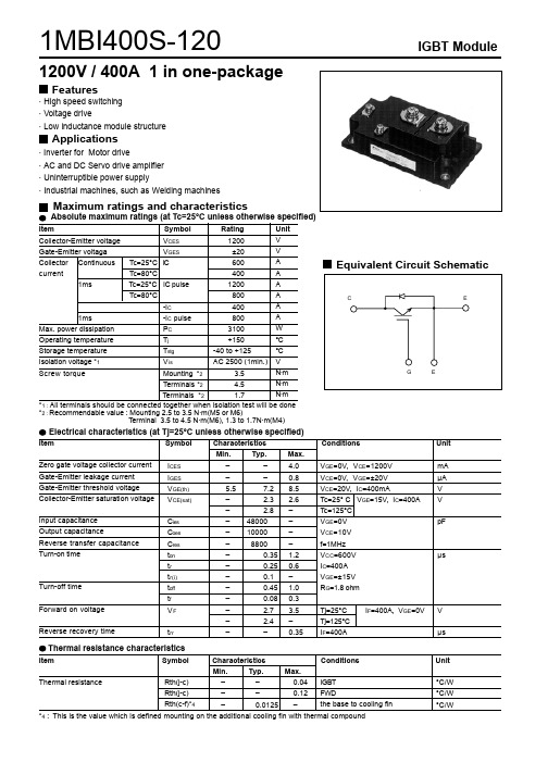
1MBI400S-120IGBT Module1200V / 400A 1 in one-packageFeatures· High speed switching · Voltage drive· Low inductance module structureApplications· Inverter for Motor drive· AC and DC Servo drive amplifier · Uninterruptible power supply· Industrial machines, such as Welding machinesMaximum ratings and characteristicsThermal resistance characteristicsThermal resistance ––0.04––0.12–0.0125 –IGBT FWD the base to cooling fin °C/W°C/W °C/W *4 : This is the value which is defined mounting on the additional cooling fin with thermal compoundItem Symbol Characteristics Conditions Unit Min. Typ. Max.Rth(j-c)Rth(j-c)Rth(c-f)*4Characteristics0123452004006008001000Collector current vs. Collector-Emiiter voltageTj= 25°C (typ.)C o l l e c t o r c u r r e n t : I c [ A ]Collector - Emitter voltage : VCE [ V ]0123452004006008001000Collector current vs. Collector-Emiiter voltageTj= 125°C (typ.)Collector - Emitter voltage : VCE [ V ]C o l l e c t o r c u r r e n t : I c [ A ]0123452004006008001000Collector current vs. Collector-Emiiter voltageVGE=15V (typ.)Collector - Emitter voltage : VCE [ V ]C o l l e c t o r c u r r e n t : I c [ A ]510152025246810Collector-Emiiter voltage vs. Gate-Emitter voltageTj= 25°C (typ.)C o l l e c t o r - E m i t t e r v o l t a g e : V C E [ V ]Gate - Emitter voltage : VGE [ V ]051015202530351000500010000100000Capacitance vs. Collector-Emiiter voltage (typ.)VGE=0V, f= 1MHz, Tj= 25°CC a p a c i t a n c e : C i e s , C o e s , C r e s [ p F]Collector - Emitter voltage : VCE [ V ]010002000300040002004006008001000Dynamic Gate charge (typ.)Vcc=600V, Ic=400A, Tj= 25°CGate charge : Qg [ nC ]C o l l e c t o r - E m i t t e r v o l t a g e : V C E [ V]0510152025G a t e - E m i t t e r v o l t a g e : V G E [ V ]0100200300400500600700501005001000Switching time vs. Collector current (typ.)Vcc=600V, VGE=+-15V, Rg= 1.8ohm, Tj= 25°CS w i t c h i n g t i m e : t o n , t r , t o f f , t f [ n s e c ]Collector current : Ic [ A ]0100200300400500600700501005001000Switching time vs. Collector current (typ.)Vcc=600V, VGE=+-15V, Rg= 1.8ohm, Tj= 125°CCollector current : Ic [ A ]S w i t c h i n g t i m e : t o n , t r , t o f f , t f [ n s e c ]0.5110505010050010005000Switching time vs. Gate resistance (typ.)Vcc=600V, Ic=400A, VGE=+-15V, Tj= 25°CGate resistance : Rg [ ohm ]S w i t c h i n g t i m e : t o n , t r , t o f f , t f [ n s e c ]020040060080020406080100Switching loss vs. Collector current (typ.)Vcc=600V, VGE=+-15V, Rg=1.8ohmS w i t c h i n g l o s s : E o n , E o f f , E r r [ m J /p u l s e ]Collector current : Ic [ A ]0.5110500100200300Switching loss vs. Gate resistance (typ.)Vcc=600V, Ic=400A, VGE=+-15V, Tj= 125°CS w i t c h i n g l o s s : E o n , E o f f , E r r [ m J /p u ls e ]Gate resistance : Rg [ ohm ]2004006008001000120014000100200300400500600700800900 Reverse bias safe operating area+VGE=15V, -VGE<=15V, Rg>=1.8ohm, Tj<=125°CCollector - Emitter voltage : VCE [ V ]C o l l e c t o r c u r r e n t : I c [ A ]Outline Drawings, mmmass : 380g200400600800Forward current vs. Forward on voltage (typ.)F o r w a r d c u r r e n t : I F [ A ]Reverse recovery characteristics (typ.)Vcc=600V, VGE=+-15V, Rg=1.8ohm1E-30.010.050.10.5T h e r m a l r e s i s t a n s e : R t h (j -c ) [ °C /W ]Pulse width : Pw [ sec ]。
富士FUJI 标准IGBT(1MBI、2MBI、6MBI),智能IPM(6MBP、7MBP、7MBR)
富士FUJI 标准IGBT(1MBI、2MBI、6MBI),智能IPM(6MBP、7MBP、7MBR) N系列第三代 IGBT模块600V 1MBI 一单元: 1MBI600NN-060 1MBI600NP-060**注:1MBI600NN-060和1MBI600NP-060是对管2MBI两单元: 2MBI50N-060 2MBI75N-060 2MBI100N-060 2MBI150N-060 2MBI200N-0602MBI200N-060-032MBI300N-060 2MBI300N-060-04 2MBI400N-060 2MBI400N-060-01 2MBI600NT-0601200V 1MBI 一单元: 1MBI200N-120 1MBI300N-120 1MBI400N-1202MBI两单元: 2MBI50N-120 2MBI75N-120 2MBI100N-120 2MBI150N-120 2MBI200N-120 2MBI300N-120 2MBI300N-120-01P系列“NPT”工艺,正温度系数1200V 1400V 1MBI一单元: 1MBI600PX-120 1MBI600PX-1402MBI两单元: 2MBI50P-140 2MBI75P-140 2MBI100PC-140 2MBI150PC-140 2MBI200PB-140 2MBI300P-140S系列第四代 IGBT模块1200V 1MBI 一单元: 1MBI300S-120 1MBI400S-1202MBI两单元: 2MBI100SC-120 2MBI150SC-120 2MBI200S-120 2MBI300S-1206MBI六单元: 6MBI10S-120 6MBI15S-120 6MBI25S-120 6MBI35S-120 6MBI50S-120 6MBI50S-140 6MBI75S-060 6MBI75S-120 6MBI75S-140 6MBI100S-060 6MBI100S-1206MBI100S-140T系列变频器专用600V 2MBI两单元: 2MBI200TA-060 2MBI300TA-060 2MBI400TB-0604MBI四单元: 4MBI75T-060 4MBI100T-060 4MBI150TA-060 4MBI200T-060U系列第五代IGBT模块600V 2MBI两单元: 2MBI150U2A-060 2MBI200U2A-060 2MBI300U2B-060 2MBI400U2B-060 2MBI600U2E-0606MBI六单元: 6MBI75U2A-060 6MBI100U2B-060 6MBI150U2B-0601200V 1MBI 一单元: 1MBI300U4-120 1MBI400U4-120 1MBI600U4-120 1MBI600U4B-120 1MBI800U4B-120 2MBI两单元: 2MBI75U4A-120 2MBI100U4A-120 2MBI150U4A-120 2MBI150U4B-120 2MBI200U4B-120 2MBI200U4D-120 2MBI200U4H-120 2MBI225U4J-120-50 2MBI225U4N-120-502MBI300U4D-120 2MBI300U4E-120 2MBI300U4H-120 2MBI300U4J-120-502MBI300U4N-120-50 2MBI400U4H-1202MBI450U4E-120 2MBI450U4J-120-50 2MBI450U4N-120-506MBI六单元: 6MBI35U4A-120 6MBI50U4A-120 6MBI75U4A-120 6MBI75U4B-1206MBI75UC-120 6MBI100U4B-120 6MBI100UC-120 6MBI150U4B-120 6MBI225U4-120 6MBI300U4-1206MBI450U4-1201700V 2MBI两单元: 2MBI100U4H-170 2MBI150U4H-170 2MBI200U4H-170 2MBI300U4H-1702MBI400U4H-1706MBI六单元: 6MBI75U4B-170 6MBI100U4B-170 6MBI150U4B-170 6MBI225U4-170 6MBI300U4-170 6MBI450U4-170大电流等级1200V1MBI 一单元: 1MBI1200U4C-120 1MBI1600U4C-120 1MBI2400U4D-120 1MBI3600U4D-120 2MBI两单元: 2MBI600U4G-120 2MBI800U4G-120 2MBI1200U4G-1201700V1MBI 一单元: 1MBI1200U4C-170 1MBI1600U4C-170 1MBI2400U4D-170 1MBI3600U4D-170 2MBI两单元: 2MBI600U4G-170 2MBI800U4G-170 2MBI1200U4G-170智能IGBT模块(IPM)一、工业级IPM:适用于变频空调,伺服控制等,内设欠压、过热、过流保护功能,开关频率最大20kHZ600V电压6MBP六单元:6MBP15RH060 6MBP20RH060 6MBP30RH060二、R系列IPM:(适用于通用变频器等,内设欠压、过热、过流保护功能)600V 电压6MBP六单元:6MBP20RTA060 6MBP50RA060 6MBP75RA060 6MBP100RA060 6MBP150RA060 6MBP200RA060 6MBP300RA060 6MBP50RTB060 6MBP50RTJ060 6MBP75RTB0606MBP75RTJ060 6MBP100RTB060 6MBP100RTJ060 6MBP150RTB060 6MBP150RTJ060 7MBP 七单元:7MBP50RA060 7MBP75RA060 7MBP100RA060 7MBP150RA060 7MBP200RA060 7MBP300RA060 7MBP50RTB060 7MBP50RTJ060 7MBP75RTB060 7MBP75RTJ0607MBP100RTB060 7MBP100RTJ060 7MBP150RTB060 7MBP150RTJ0601200V 电压6MBP六单元: 6MBP15RA120 6MBP25RA120 6MBP50RA120 6MBP50RJ120 6MBP75RA120 6MBP75RJ120 6MBP100RA120 6MBP150RA1207MBP 七单元:7MBP25RA120 7MBP25RJ120 7MBP50RA120 7MBP50RJ1207MBP75RA120 7MBP75RJ120 7MBP100RA120 7MBP150RA120PIM(智能功率集成模块)含整流桥七单元600V电压7MBR20SC060 7MBR30SA060 7MBR30SC060 7MBR50SA060 7MBR50SB060 7MBR50SC060 7MBR75SB060 7MBR75SD060 7MBR100SB060 7MBR100SD0601200V电压7MBR10SA120 7MBR10SC120 7MBR15SA120 7MBR15SC120 7MBR25SA120 7MBR25SC120 7MBR35SB120 7MBR35SD120 7MBR50SB120 7MBR50SD1201400V电压7MBR10SA140 7MBR15SA140 7MBR25SA140 7MBR35SB140 7MBR50SB140。
6MBI225U-120中文资料
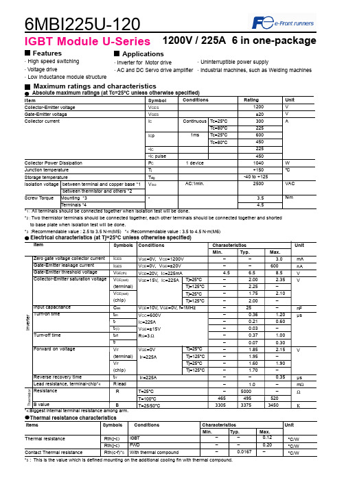
6MBI225U-1201200V / 225A 6 in one-packageFeatures· High speed switching· Voltage drive· Low inductance module structureApplications · Inverter for Motor drive· AC and DC Servo drive amplifierMaximum ratings and characteristicsThermal resistance characteristicsThermal resistanceContact Thermal resistance––0.12––0.20–0.0167 –IGBTFWDWith thermal compound°C/W°C/W°C/W*2 : Two thermistor terminals should be connected together, each other terminals should be connected together and shortedto base plate when isolation test will be done.*3 :Recommendable value : 2.5 to 3.5 N·m(M5) *4 :Recommendable value : 3.5 to 4.5 N·m(M6)Rth(j-c)Rth(j-c)Rth(c-f)*5IGBT Module U-Series*5 : This is the value which is defined mounting on the additional cooling fin with thermal compound.4Items Symbols Conditions Characteristics UnitMin.Typ. Max.· Uninterruptible power supply· Industrial machines, such as Welding machinesCharacteristics (Representative)VGE=0V, f= 1MHz, Tj= 25°CVcc=600V, I=225A, Tj= 25°CCollector current vs. Collector-Emitter voltage (typ.)Tj= 125°C / chipCapacitance vs. Collector-Emitter voltage (typ.)Dynamic Gate charge (typ.)Collector current vs. Collector-Emitter voltage (typ.)Tj= 25°C / chipCollector current vs. Collector-Emitter voltage (typ.)VGE=15V / chipTj=25°C / chipCollector-Emitter voltage vs. Gate-Emitter voltage (typ.)010020030040050060012345C o l l e c t o r c u r r e n t : I c [A ]VGE=20V15V12V10V8V010020030040050060012345C o l l e c t o r c u r r e n t : I c [A ]VGE=20V 15V12V10V8V010020030040050060001234C o l l e c t o r c u r r e n t : I c [A ]Tj=125°CTj=25°C246810510152025C o l l e c t o r - E m i t t e r v o l t a g e : V C E [ V ]Ic=450A Ic=225A Ic= 112.5A0.11.010.0100.0102030C a p a c i t a n c e : C i e s , C o e s , C r e s [ n F ]200400600800100012001400C o l l e c t o r -E m i t t e r v o l t a g e : V C E [ 200V /d i v ]G a t e - E m i t t e r v o l t a g e : V G E [ 5V /d i v]Vcc=600V, Ic=225A, VGE=±15V, Tj= 25°CStray inductance <= 100nHSwitching loss vs. Collector current (typ.)Vcc=600V, VGE=±15V, Rg=3ΩVcc=600V, Ic=225A, VGE=±15V, Tj= 125°C+VGE=15V,-VGE <= 15V, RG >= 3Ω ,Tj <= 125°CSwitching time vs. Collector current (typ.)Vcc=600V, VGE=±15V, Rg=3Ω, Tj=125°CSwitching time vs. Gate resistance (typ.)Switching time vs. Collector current (typ.)Vcc=600V, VGE=±15V, Rg=3Ω, Tj= 25°CReverse bias safe operating area (max.)Switching loss vs. Gate resistance (typ.)10100100010000100200300400S w i t c h i n g t i m e : t o n , t r , t o f f , t f [ n s e c ]Collector current : Ic [ A ]10100100010000100200300400S w i t c h i n g t i m e : t o n , t r , t o f f , t f [ n s e c ]Collector current : Ic [ A ]10100100010000110100S w i t c h i n g t i m e : t o n , t r , t o f f , t f [ n s e c ]Gate resistance : Rg [ Ω ]trtftoffton 01020304050100200300400500S w i t c h i n g l o s s : E o n , E o f f , E r r [ m J /p u l s e ]Collector current : Ic [ A ]Eon(125°C)Eon(25°C)Eoff(125°C)Err(125°C)Err(25°C)Eoff(25°C)0255075100125150110100S w i t c h i n g l o s s : E o n , E o f f , E r r [ m J /p u l s e ]Gate resistance : Rg [ Ω ]EoffErrEon0100200300400500600200400600800100012001400C o l l e c t o r c u r r e n t : I c [ A ]Collector - Emitter voltage : VCE [ V ]Transient thermal resistance (max.)Reverse recovery characteristics (typ.)Vcc=600V, VGE=±15V, Rg=3ΩForward current vs. Forward on voltage (typ.)chipTemperature characteristic (typ.)01002003004005006001234F o r w a r d c u r r e n t : I F [ A ]Forward on voltage : VF [ V ]Tj=125°CTj=25°C101001000100200300400500R e v e r s e r e c o v e r y c u r r e n t : I r r [ A ]R e v e r s e r e c o v e r y t i m e : t r r [ n s e c ]Forward current : IF [ A ]Irr (125°C)Irr (25°C)trr (125°C)trr (25°C)0.0010.0100.1001.0000.0010.0100.1001.000T h e r m a l r e s i s t a n s e : R t h (j -c ) [ °C /W ]Pulse width : Pw [ sec ]0.1110100-60-40-20020406080100120140160180Temperature [°C ]R e s i s t a n c e : R [ k Ω ]Outline Drawings, mmM6296MBI225U-120IGBT ModuleEquivalent Circuit Schematic[Thermister]135111210987246[Inverter]。
1MBI400U-120资料
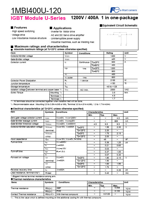
VGE=0V IF=400A
IF=400A
Tj=25°C Tj=125°C Tj=25°C Tj=125°C
Min. – – 4.5 – – – – – – – – – – – – – – – –
Typ. – – 6.5 1.95 2.20 1.75 2.00
45 0.36 0.21 0.03 0.37 0.07 1.80 1.90 1.60 1.70 – 0.40
Input capacitance Turn-on time
Turn-off time Forward on voltage
Reverse recovery time Lead resistance, terminal-chip*3
ICES IGES VGE(th) VCE(sat) (terminal) VCE(sat) (chip) Cies ton tr tr(i) toff tf VF (terminal) VF (chip) trr R lead
Ic=200A
0
5
10
15
20
25
Gate - Emitter voltage : VGE [ V ]
Dynamic Gate charge (typ.) Vcc=600V, Ic=400A, Tj= 25°C
VGE
Collector current : Ic [A]
Collector-Emitter voltage : VCE [ 200V/div ] Gate - Emitter voltage : VGE [ 5V/div ]
12V
600
10V 400
200
0 0
8V
1
2
3
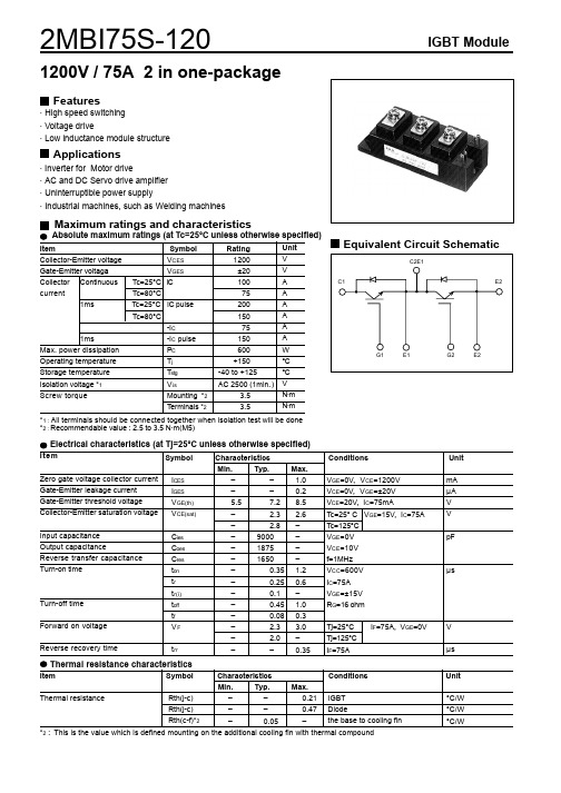
2MBI75S-120中文资料
Err
0
1
10
100
500
Gate resistance : Rg [ohm]
Collector current : Ic [ A ]
Switching loss : Eon, Eoff, Err [ mJ/pulse ]
ton tr
tf 100
50
0
20
40
60
80
100
120
Collector current : Ic [ A ]
Switching loss vs. Collector current (typ.) Vcc=600V, VGE=±15V, Rg=16ohm
20
Eon(125°C)
15
Eon(25°C)
10 Eoff(125°C)
Eoff(25°C)
5
Err(125°C)
Err(25°C)
0
0
20
40
60
80 100 120 140
IGBT Module
180 160 140 120 100
80 60 40 20
0 0
Collector current vs. Collector-Emiiter voltage Tj= 125°C (typ.) VGE= 20V15V 12V
10V
8V
1
2
3
4
5
Collector - Emitter voltage : VCE [ V ]
Equivalent Circuit Schematic
C2E1
C1
E2
G1
E1
G2
E2
Electrical characteristics (at Tj=25°C unless otherwise specified)
- 1、下载文档前请自行甄别文档内容的完整性,平台不提供额外的编辑、内容补充、找答案等附加服务。
- 2、"仅部分预览"的文档,不可在线预览部分如存在完整性等问题,可反馈申请退款(可完整预览的文档不适用该条件!)。
- 3、如文档侵犯您的权益,请联系客服反馈,我们会尽快为您处理(人工客服工作时间:9:00-18:30)。
Switching time vs. Collector current (typ.)
Vcc=600V,VGE=±15V, Rg=51Ω,Tj=25oC 1000
500
toff
ton tr
100 tf
50 0
10
20
30
40
Collector current : Ic [ A ]
Switching time vs. Gate resistance (typ.) Vcc=600V,Ic=25A,VGE=±15V, Tj=25oC 5000
· Inverter for motor drive · AC and DC servo drive amplifier · Uninterruptible power supply · Industrial machines, such as welding machines
Maximum ratings and characteristics
Reverse recovery time
trr
Characteristics
Min.
Typ.
–
–
–
–
5.5
7.2
–
2.3
–
2.8
–
3000
–
625
–
550
–
0.35
–
0.25
–
0.1
–
0.45
–
0.08
–
2.5
–
2.0
–
–
Max. 1.0 0.2 8.5 2.6 – – – – 1.2 0.6 – 1.0 0.3 3.3 – 0.35
Forward current : IF [ A ]
Transient thermal resistance 5
FWD
1 IGBT
Thermal resistanse : Rth(j-c) [ oC/W ]
0.1
0.01 0.001
0.01
0.1
Pulse width : Pw [ sec ]
Outline Drawings, mm
Conditions
VGE=0V, VCE=1200V VCE=0V, VGE=±20V VCE=20V, IC=25mA Tj=25°C VGE=15V, IC=25A Tj=125°C VGE=0V VCE=10V f=1MHz VCC=600V IC=25A VGE=±15V RG=51Ω
Tj=25°C Tj=125°C IF=25A
1000
Cies
Capacitance : Cies, Coes, Cres [ pF ]
100 0
Coes Cres
5
10
15
20
25
30
35
Collector - Emitter voltage : VCE [ V ]
Collector - Emitter voltage : VCE [ V ]
Collector current : Ic [ A ]
40
30
10V
20
10
0 0
1
2
3
4
Collector - Emitter voltage : VCE [ V ]
8V 5
Collector current : Ic [ A ]
Collector current vs. Collector-Emitter voltage VGE=15V (typ.)
14(W )
Electrical characteristics (Tj=25°C unless otherwise specified)
Item
Symbol
Zero gate voltage collector current Gate-Emitter leakage current Gate-Emitter threshold voltage Collector-Emitter saturation voltage
Unit
°C/W °C/W °C/W
元器件交易网
6MBI25S-120
Characteristics
Collector current vs. Collector-Emitter voltage Tj= 25 oC (typ.)
60
VGE= 20V 15V 12V 50
IGBT Modules
Forward current : IF [ A ]
Forward current vs. Forward on voltage (typ.) 60
Tj=125 oC
Tj=25 oC
50
40
30
Reverse recovery characteristics (typ.) Vcc=600V,VGE=±15V, Rg=51Ω
Absolute maximum ratings (Tc=25°C unless otherwise specified)
Item
Symbol
Collector-Emitter voltage
VCES
Gate-Emitter voltage
VGES
Collector Continuous Tc=25°C IC
M623
1
4-ø6.1±0.3 2-ø5.5±0.3
16.02
15.24
107.5±1 93±0.3 15.24 15.24
15.24
17
13
69.6±0.3
ø2.5±0.1
1.5 6
27.6±0.3
45±1 41.91 32±0.3
+ 0.5
11 0
93±0.3
1
3.81 16.02 11.43 11.43 11.43 11.43 11.43
40
10V 30
20
10
0 0
8V
1
2
3
4
5
Collector - Emitter voltage : VCE [ V ]
Collector-Emitter voltage vs. Gate-Emitter voltage
Tj= 25 oC (typ.) 10
8
6
4 2 0
5
1000
Ic= 50A Ic= 25A Ic= 12.5A
Gate - Emitter voltage : VGE [ V ]
元器件交易网 6MBI25S-120
IGBT Modules
Switching time : ton, tr, toff, tf [ nsec ]
Switching time : ton, tr, toff, tf [ nsec ]
Rth(j-c)
–
–
1.30 FWD
Rth(c-f)*2
–
0.05
–
the base to cooling fin
*2 : This is the value which is defined mounting on the additional cooling fin with thermal compound
元器件交易网
6MBI25S-120
IGBT MODULE ( S series) 1200V / 25A 6 in one-package
Features
· Compact package · P.C.board mount · Low VCE(sat)
Applications
Err
0
10
50
100
500
Gate resistance : Rg [ Ω ]
Switching time : ton, tr, toff, tf [ nsec ]
Collector current : Ic [ A ]
Switching loss : Eon, Eoff, Err [ mJ/pulse ]
ICES IGES VGE(th) VCE(sat)
Input capacitance Output capacitance Reverse transfer capacitance Turn-on time
Turn-off time
Diode forward on voltage
Cies Coes Cres ton tr tr(i) toff tf VF
1000
500 toff
ton
tr 100
tf
50 10
50
100
500
Gate resistance : Rg [ Ω ]
Switching loss vs. Gate resistance (typ.)
Vcc=600V,Ic=25A,VGE=±15V,Tj=125oC 20
15 Eon
10
5 Eoff
IGBT Modules
Equivalent Circuit Schematic
13(P)
1(G u) 2 (E u)
3(G x) 4 (E x ) 17(N)
5(G v)
6 (E v) 16(U)
7(G y) 8 (E y)
9(G w)
1 0 (E w) 15(V)
11(G z)
1 2 (E z)
current
Tc=80°C
1ms
Tc=25°C IC pulse
Tc=80°C
-IC
1ms
-IC pulse
Max. power dissipation (1 device) PC