同步电机说明书(英文)
LSM系列交流永磁同步伺服电动机使用说明书

LSM系列交流永磁同步伺服电动机使用说明书感谢您使用本公司交流永磁同步伺服电动机(以下简称电机),操作电机前需充分了解本公司的电机型号规格和使用说明书。
安装电机前特别需要注意安全预防措施!安全预防措施非正确使用本电机会造成重大的人身和财产事故。
所有接触电机接线端子的工作必须由有资格的专业人员完成。
请确认电机的供电已被切断且肯定不会再被接通。
1.安全提示1)在对电机或电机驱动器进行任何工作前,请切断供电且确认不会再被接通,旋转部件须处于静止状态。
2)SQ系列电机旋转时,电机端子上有高压,它能导致人身事故。
3)装有阻转制动器的电机,请检查其工作无误,阻转制动器仅用于电机停转的情况下。
允许的紧急制动次数,请查阅电机目录中有关摩擦片的数据。
不允许将阻转制动器作为工作制动器使用。
只允许本公司或经本公司授权的服务站进行维修工作。
4)电机表面温度会超过60℃。
不允许在电机附近放置或在电机上安装对温度敏感的物件。
必要时,须采取防人身接触措施。
2.拆封检查:客户收到电机后,请立即检查以下事项:1)检查电机外观和配件是否有损坏等异常情况。
2)检查电机配线是否毁坏,是否可与电机相连接。
3)电机型号与您定单上的型号是否相同,如有任何不符请与我公司业务处联系。
3.运输、安装和仓储1)搬运电机时不可拖拉电机引出线或紧握电机主轴。
2)安装电机连接器时请勿敲击电机主轴和后罩壳以防止损坏电机轴承和精密反馈元件。
3) 安装时,请注意将电机放在平整的平面上,法兰盘要固定好。
机械部分连接时,请注意上下左右要调准。
偏差将导致不允许的振动,并会损伤轴承和机械耦合部件。
4) 要采用与电机适配的电机驱动器。
请查阅相关产品文件或咨询我公司技术人员。
超过允许的最大电机电流值时,会立刻导致电机永磁体的去磁。
5)只允许存放于干燥,无粉尘以及通风的房间内。
使用前,请用500V兆欧表检查绝缘。
如绕组对机壳的绝缘电阻≤2MΩ,电机在使用前须烘干。
6)长期存放后(大于三个月),为使轴承中的润滑油得以均匀分布,应让电机短时地低速运转,速度为500rpm.如自行装卸电机引起任何问题,恕不负责。
永磁同步电机英文

Permanent magnet synchronous motorWorksSynchronous generator in order to achieve the energy conversion, the need for a DC magnetic field. The magnetic field generated direct current, called the generator excitation current. According to the excitation current supply mode, all obtained from other power generator excitation current, known excited generators, excitation power obtained from the generator itself, it is called self excited generator.Work1, the generator excitation current in several ways to obtain1) DC generator excitation modeThis excitation mode of the generator has a dedicated DC generator, this dedicated DC generator called DC exciter, exciter generally coaxial with the generator, the generator field winding mounted on a large shaft through slip rings and fixed brush to get the DC current from the exciter. This excitation mode with the excitation current independent, work is more reliable and reducing electricity consumption from the advantages of the past few decades the main generator excitation mode, with a more mature operating experience. Excitation drawback is slower, maintenance workload, it is more than 10MW units rarely used.2) AC exciter excitation mode power supplySome of the modern large-capacity generator provides AC exciter field current. AC exciter shaft is mounted on the large generator, which outputs the rectified AC power is supplied through the rotor excitation generator, time, the generator excitation mode excitation mode are His, and the use of stationary fairing, so called Reed for his static excitation, AC pilot exciter provides excitation current. AC permanent magnet pilot exciter measuring device can be machine or device with a self-excitation constant voltage alternator. In order to improve the speed excitation regulator, AC exciter usually 100 - 200HZ IF generators, while the AC pilot exciter is used 400 - 500HZ IF generators. The generator field winding and three-phase alternating current windings are wound in the stator slots, the rotor teeth and grooves only without winding, like a gear, so that it is no brushes, slip rings and other rotating parts, with reliable , simple structure and easy manufacturing process. Drawback is noisy, the harmonic components of the AC potential is large.3) No exciter excitation modeIn excitation mode is not set up special exciter and excitation power obtained from the generator itself, and then supplied by the rectifier exciter generator itself, said self-commutated static excitation. Self-commutated static excitation can be divided into self-healing and self-shunt excitation in two ways. It does this by way of self-shunt connected to the outlet of the generator excitation current rectifier transformer to obtain, after rectification supply generator excitation, this excitation mode with a simple knot, less equipment, less investment and less maintenance, etc.. Since the complex excitation mode in addition to a rectifier transformer, it also has a series of high-power in the generator stator circuit current transformer. The role of such a transformer in the event of a short circuit to provide a larger excitation current generator to compensate for the lack of the rectifier transformer output. This excitation mode has two excitation power, obtained through the rectifier transformer voltage supply and through a series transformer current source. Relevant characteristics1, the voltage regulationAutomatic adjustment of excitation can be seen as a system to adjust the amount of voltage of thenegative feedback control system. Reactive load current is caused by the main generator terminal voltage drops when the excitation current is constant, the generator terminal voltage will vary with the reactive current increases. However, in order to meet user requirements for power quality, the generator terminal voltage should be essentially unchanged, the way to achieve this requirement is to change with the reactive current regulator generator excitation current.2, the regulation of reactive power:Generator running in parallel with the system can be considered as large-capacity power and infinite bus run, to change the generator excitation current, EMF and the stator current also followed changes, then the generator reactive current changes also followed. When the generator with infinite capacity systems operating in parallel, in order to change the reactive power of the generator, the generator excitation current must be adjusted. At this point changing excitation current is not usually called "surge", but just changed into the system reactive power.3, reactive load distribution:Parallel operation of generators according to their rated capacity, in proportion to the reactive current assignment. Large capacity generators should pay more reactive load, while the smaller capacity is negative provide less reactive load. To achieve the reactive load can be automatically assigned, by automatically adjusting the excitation means high pressure, changing excitation current to maintain its terminal voltage is constant, but also on the characteristics of the generator voltage regulator to adjust the tilt to achieve the parallel operation of the generator the rational allocation of reactive load.Automatic adjustmentChanging the excitation current of the generator in general, not directly in the rotor circuit for, as the large current circuit is not easy to direct regulation, commonly used method is to change the exciter field current of the generator in order to achieve adjustment rotor current purposes. Commonly used methods to change the exciter field circuit resistance to change additional exciter field current changeSCR conduction angle. Here is mainly about changing the thyristor conduction angle method, which is based on the generator voltage, current or power factor changes, changes accordingly thyristor conduction angle, so the generator excitation current will change accordingly. This device generally consists of transistors, thyristors electronic components, the sensitive, rapid, non-failure zone, output power, small size and light weight advantages. In case of accident can effectively inhibit the generation of over-voltage and fast excitation. Automatic adjustment of excitation devices are usually by the measurement unit, the synchronization unit, an amplifier, difference adjustment unit, stabilization unit, limiting unit, and some auxiliary units. Signal to be measured (such as voltage, current, etc.), the measurement unit transformation compared with the given value, and then compare the results (deviation) after pre-amplification unit and power amplification unit amplified and used to control the thyristor conduction angle, adjust the excitation current in order to achieve the purpose. Synchronization unit's role is to make part of the output of the phase shift trigger pulse thyristor rectifier with AC excitation power synchronization to ensure correct silicon controlled trigger. Droop unit's role is to make the parallel operation of the generator can be a stable and reasonable allocation of reactive loads. Stabilization unit is to improve the stability of the power system and the introduction of elements. Excitation system stabilizing unit for improving the stability of the excitation system. Limiting unit is to enable the generator will not over-or under-excitation excitation operation under theconditions and settings. Must be noted that not every kind of automatic adjustment of excitation devices have the various units, a regulator device has the units responsible for specific tasks related to their.Auxiliary equipmentAutomatically adjust the excitation voltage transformer organic component parts, machine-side current transformer, excitation transformer; excitation device will need to provide the following current, Plant AC380v, Plant DC220v control power switch on the power plant with DC220v; need to provide the following empty contacts , automatic boot. automatically shut down. Grid (one normally open, one normally closed) increases or decreases; need to provide the following analog signal generator terminal voltage of 100V, generator terminal current of 5A, bus voltage 100V, excitation device outputs the following relay contact signal; excitation transformer overcurrent, loss of excitation, excitation device abnormalities.Excitation control, protection and signal routing excitation switch back to help the magnetic circuit, fans, excitation switch steal jump, excitation transformer overcurrent regulator failure, abnormal working conditions generator, power transmitter and other components. In the synchronous generator of an internal failure in addition to splitting, it must also de-excitation, the rotor magnetic field weakening as quickly as possible to the minimum extent, but in the case to ensure the rotor, so that excitation shortest possible time, is the main excitation device function. The size of the rated excitation voltage excitation can be divided into linear and nonlinear resistor resistor excitation.Over the past decade, as new technologies, new technology and the emergence of new devices and use, making the generator excitation mode has been continuously developed and refined. In the automatic adjustment of excitation installations, but also continue to develop and promote the use of many new adjustment device. As the use of computer software for computer automatic adjustment of excitation device has significant advantages, many countries are in the development and testing of a computer with a microcomputer with a corresponding number of external devices constitute automatic adjustment excitation device, this device will be able to achieve self-regulation adapt to the best adjustment.The method is called to obtain the excitation current excitation mode. Currently used in the field is divided into two categories: one category is used as a DC generator excitation power of the DC exciter excitation system; another rectifier unit is converted into DC after the AC supply rectifier exciter excitation system. Is as follows:A DC-DC exciter exciter field generally coaxial with the synchronous generator, using shunt or excited connection. Reed uses his connection, the exciter field current by another deputy exciter called coaxial DC generator supply. As shown in Figure 15.5.2 Still the same axis with three rectifier exciter alternator, that is the main generator, AC main exciter exciter and exchange deputy. Vice exciter excitation current starts by the external DC power supply, to be built up and then converted to self-excitation voltage (sometimes using the generator). Vice exciter output current through the static thyristor rectifier rectifier supply main exciter and main exciter AC output current through the stationary phase bridge rectifier silicon rectifier supplies the main generator field winding. (See Figure 15.6)3 stationary rotating rectifier exciter rectifier DC output must brush and collector ring to the rotating field windings transported, for large-capacity synchronous generator, the excitation current of several thousand amperes, so that the collector ring serious overheating. Therefore, inthe large-capacity synchronous generator, often using brushes and slip rings without rotating rectifier excitation system, as shown in Figure 15.7. Main exciter armature is rotating three-phase synchronous generator, the AC current flows through the armature rotates together with the spindle rotating silicon rectifier rectifier directly to the main generator rotor field winding. AC main exciter excitation current from the coaxial communication via stationary pilot exciter rectifier thyristor rectifier supply. Because of this excitation system canceled the collector ring and brush gear, also called brushless excitation system.Advantages: Synchronization can be used when the generatorDisadvantages: easily broken brush motor complex structure, high costInsulation resistance tester optical fiber tensile testing machine barrel pump metering pump high and low temperature alloy analyzer Temperature Transmitter Infrared Thermometer Sichuan bulk SMS composite salt spray corrosion test chamber mixer noise meter metallic elemental analyzer pall ring stainless steel instrumentation valves Electromagnetic Flowmeter electric actuator pressure transmitter SwirlmeterControl strategy1 IntroductionIn recent years, with the power electronics technology, microelectronics, new motor control theory and the rapid development of rare earth permanent magnetic materials, permanent magnet synchronous motor speedy popularization and application. With conventional electrically excited synchronous motor compared to the permanent magnet synchronous motor, especially rare earth permanent magnet synchronous motor has less wear and tear, high efficiency, energy-saving effect is obvious advantages. Permanent magnet synchronous motor with permanent magnet excitation provided the motor structure is relatively simple, reducing the machining and assembly costs, and eliminates the need for error-prone collector ring and brush to improve the reliability of motor operation; because without excitation current, no excitation loss, improved motor efficiency and power density, so it is more research in recent years, and is widely applied in various fields as a motor. In energy conservation and environmental protection and more attention today, it is very necessary for their research. Therefore. Here the permanent magnet synchronous motor control strategies are reviewed and introduced permanent magnet synchronous motor control system, the various control strategies development. [1]2 The mathematical model of permanent magnet synchronous motorsWhen the permanent magnet synchronous motor stator pass into the three-phase alternating current, three-phase current in the stator winding resistance voltage drop. The three-phase alternating current generated by the rotation of the armature magnetomotive force and the magnetic field created by the armature, on the one hand cut the stator windings and the induced electromotive force generated in the stator windings; other electromagnetic force to the rotor to synchronize the rotational speed drag. Armature current will produce only intersects with the stator winding of the stator winding chain leakage flux and the stator leakage induced electromotive force generated in the windings. Furthermore, the rotor magnetic field generated by the permanent magnet synchronous speed to cut the stator windings. Resulting in no-load electromotive force. To facilitate analysis, mathematical models, assume the following parameters: ①ignore the motor core saturation; ②the motor without hysteresis loss and eddy current; ③the stator and the rotor magnetomotive force along the magnetic field generated by the inner circle of the stator sinusoidal , ignoring all the space harmonics magnetic field; ④symmetricalwindings of each phase, i.e. the number of turns of each phase winding resistance of the same, with the axis of the mutual displacement of the same electrical angle.The analysis of the mathematics of the synchronous motor, often using two-phase synchronous rotating (d, q) coordinate system and the two-phase stationary (α, β) coordinate system. Figure 1 shows the permanent magnet synchronous motor (d, q) rotating coordinate system mathematical model.(1) The stator voltage equation is:Where: r is the stator winding resistance; p is the differential operator, p = d / dt; id, iq for the stator current; ud, uq is the stator voltage; ψd, ψq respectively, flux in d, q-axis component of ; ωf is the rotor angular velocity (ω = ωfnp); np f or the motor pole pairs.(2) the stator flux equation:Where: ψf is the rotor flux.(3) electromagnetic torque is:Where: J is the moment of inertia of the motor.If the motor is a salient pole motor, then Ld = Lq, select id, iq and the motor mechanical angular velocity ω is the state variable, which can have the status of permanent magnet synchronous motor equation:By the formula (7) shows that the three-phase permanent magnet synchronous motor is a multi-variable system, and id, iq, ω nonlinear coupling exists between the relationship, in order to achieve high-performance three-phase permanent magnet synchronous motor control, is a challenging task.Three permanent magnet synchronous motor control strategiesAny electromagnetic torque motors are the main magnetic field and the magnetic field generated by the interaction of the armature. DC motor armature main magnetic field and the magnetic field in the spatial difference between each 90 °, it can be adjusted independently; AC motor armature main magnetic field and the magnetic field is not perpendicular to each other, influence each other. Thus, a long time, the AC motor torque control performance is poor. After a long study, the current AC motor control with constant frequency ratio control, vector control, direct torque control scheme.3.1 Constant ratio controlConstant ratio control is an open loop control. It is based on a given system, using space vector pulse width modulation conversion uout the desired output voltage is controlled to operate the motor at a certain speed. Dynamic performance requirements in some places, because the open-loop VVVF control is simple, is still widely used for general speed control system, but because of the steady-state model based on the motor, you can not get a good dynamic control performance, Therefore, the motor must be based on a dynamic mathematical model. Permanent magnet synchronous motor is nonlinear dynamic mathematical model, multi-variable, which contains ω with id or iq product terms, so to get an accurate d ynamic control performance, must be ω and id, iq decoupling. In recent years, research various nonlinear controller is used to solve the nonlinear characteristics of permanent magnet synchronous motor.3.2 Vector controlHigh-performance AC drive system requires the support of modern control theory, for the AC motor, was undoubtedly the most widely used vector control program. Since 1971, Siemens F. Blaschke proposed vector control principle, the control scheme to favorites. Therefore, its in-depthstudy.Vector control of the basic idea is: in ordinary three-phase AC motor torque DC motor to simulate the control law, a vector field orientation coordinate transformation, the three-phase AC current into the stator of the motor excitation current component and a torque current component, perpendicular to each other and to these two components, independently of each other, and then were adjusted to attain the same as the DC motor good dynamic characteristics. Therefore, the vector control is the key to the stator current amplitude and the spatial position (frequency and phase) control. Vector control is designed to improve the torque control performance, the final implementation is id, iq control. Since the stator side are AC physical quantities, the space vector in space synchronous rotational speed, therefore, the adjustment, control and calculation is not easy. Requires the use of complex coordinate transformation vector control, but depends heavily on the motor parameters, it is difficult to ensure complete decoupling of the control ineffective. 3.3 Direct Torque ControlVector control scheme is an efficient AC servo motor control scheme. But because of the need for complex vector rotation transformation, and is less than the electromagnetic motor mechanical constant constant, it can not quickly respond to the torque vector control. Vector control for this shortcoming, the German scholar Depenbrock in the 1980s proposed a fast torque response control scheme, namely, direct torque control (DTC). This control scheme abandoned decoupled vector control thoughts and current feedback control link, take the stator flux oriented approach, the use of discrete two-point control directly to the motor stator flux and torque regulation, has a simple structure, the advantages of fast torque response. DTC was first used induction motor, 1997 L Zhong et al DTC algorithm to transform it for permanent magnet synchronous motor control, there are relevant simulation and experimental study.DTC method flux and torque of double-loop control. After getting the motor flux and torque values, the permanent magnet synchronous motor can be DTC. Figure 2 shows the PMSM DTC program structure diagram. It consists of permanent magnet synchronous motor, inverter, the torque estimate, and the voltage vector flux estimation table and other aspects of switch components, wherein ud, uq, id, iq is stationary (d, q) coordinate system voltage, the current component .Although the DTC research has made great progress, but in theory and in practice is not mature enough, for example: low-speed performance, with a load capacity, etc., but its real-time requirements, calculate the volume.3.4 Decoupling ControlMathematical model of permanent magnet synchronous motor by coordinate transformation, id, id still exist between the coupling can not be achieved on the id and iq independent regulation. To make permanent magnet synchronous motor to get a good dynamic and static performance, we must solve the id, iq decoupling problem. If we can control id is always 0 for permanent magnet synchronous motor can be simplified equation of state is:At this point, id and iq no coupling relationship, Te = npψfiq, independent regulation iq can be achieved torque linearization. Id achieve decoupling control constant is zero, can be decoupled and the voltage-current decoupling. The former is a complete decoupling control scheme that can be used for id, iq completely decoupled, but the realization of more complex; latter is an approximate decoupling control scheme, control principle is: id appropriately selected parameters of the ring current regulator , it has a considerable gain, and always make the controller referenceinput command id * = O, obtained id ≈id * = 0, iq ≈iq * o, so that you get the approximate decoupling permanent magnet synchronous motor. Figure 3 shows a vector-based control and id * = O decoupling control of permanent magnet synchronous motorControl system block diagram.Although current decoupling control scheme can not be completely decoupled, but still is an effective control method, as long as a good approach to take, it can get high-precision torque control. Therefore, the use of current decoupling engineering control scheme more. However, current decoupling control can only be achieved motor current and speed static decoupling, if the dynamic coupling affects motor control accuracy. In addition, current decoupling control by the coupling of a constant term, will introduce a lagging power factor.4 ConclusionThe permanent magnet synchronous motor has advantages and disadvantages of the various control strategies, practical application should be based on performance requirements adopted with suitable control strategy to get the best performance. Permanent magnet synchronous motor with its excellent performance, the control strategy has made a lot of achievements, I believe necessarily permanent magnet synchronous motor is widely used in various fields of national economy.ApplicationsAccording to different requirements of industrial and agricultural production machinery, motor drive is divided into fixed-speed drives, adjustable speed drives and precision control drive categories.1, the constant speed driveIndustrial and agricultural production requires a large number of production machinery continuously at a constant speed in one direction substantially run, for example fans, pumps, compressors, general machine tools and so on. Most of this type of machinery in the past three-phase or single-phase induction motor to drive. Asynchronous motor low cost, simple structure, reliable, easy maintenance, it is suitable for driving such equipment. However, the asynchronous motor efficiency, low power factor, loss, and wide use of such motor capacity, so there is a lot of energy is wasted in use. Secondly, the extensive use of agricultural and industrial fans, pumps often also need to adjust the flow rate, typically by adjusting the throttle valve to complete, which has wasted a lot of energy. Since the 1970s, people use the inverter adjust fan, water pump asynchronous motor speed to adjust their flow, to achieve significant energy savings, but the cost of the inverter has limited its use, and low efficiency of asynchronous motor itself still exists.For example, home air conditioning compressors were originally single-phase asynchronous motors, switching control its operation, noise, and high rate of temperature change is the lack of it. The early 1990s, first in Japan, Toshiba compressor control on the use of variable speed induction motor, variable speed advantages to promote the development of inverter air conditioner. In recent years, Japan's Hitachi, Sanyo and other companies began to replace the use of permanent magnet brushless motor variable speed induction motor, significantly improve efficiency, better energy efficiency and further reduce the noise in the same rated power and rated speed Next, set a single-phase induction motor to the size and weight of 100%, the permanent magnet brushless DC motor has a volume of 38.6%, 34.8% by weight, with a copper content of 20.9%, with an iron content of 36.5% efficiency 10% or more, and speed convenient, price and variable speedinduction motor fairly. Permanent magnet brushless DC motor in the air conditioning system to promote the upgrading of the air-conditioning agents.Another example is a large number of instruments and other equipment used for the cooling fan in the past have adopted the single-phase induction motor drive outer rotor structure, its size and weight, low efficiency. In recent years it has been completely permanent magnet brushless DC motor drive brushless fan replaced. The rapid development of modern information such as a variety of computer equipment is no exception, with a brushless fan. Over the years, the use of brushless fan has formed a complete series, varieties and specifications, frame sizes from 15mm to 120mm total of 12 species, thickness 6mm to 18mm frame of seven kinds, a DC voltage specifications 1.5V, 3V, 5V, 12V, 24V, 48V, speed range from 2100rpm to 14000rpm, divided into low speed, medium speed, high speed and ultra-high speed four kinds, life of 30,000 hours or more, external rotor motor is a permanent magnet brushless DC motor.Practice in recent years shows that, when the power is not greater than 10kW and the occasion of continuous operation, to reduce the volume, save materials, increase efficiency and reduce energy consumption and other factors, more and more being asynchronous motor drive brushless DC motor gradually replaced. In the case of larger power due to the cost and time investment is large, in addition to permanent magnet materials, but also the larger power drives, it is also less likely to have applied.2 speed driveA considerable number of working machinery, its speed be arbitrarily set and adjust, but the speed control accuracy requirements are not very high. Such drive systems in the packaging machinery, food machinery, printing machinery, material handling machinery, textile machinery and transport vehicles have large number of applications.In such applications the initial speed is the most widely used DC motor speed control system, after 70 years with the power electronics and control technology, variable speed induction motor quickly penetrate to the original DC drive system applications . This is because on the one hand asynchronous motor variable speed system performance price fully comparable with DC drive system, on the other hand, compared asynchronous motor with DC motor has a large capacity, high reliability, interference, long life and other advantages. Therefore, asynchronous motor VVVF quickly replaced on many occasions DC speed control system.AC permanent magnet synchronous motor because of its small size, light weight, high efficiency and a series of advantages, has drawn increasing attention, and its control technology matures, the controller has been productized. Small power induction motor variable speed permanent magnet synchronous motor is gradually replaced by speed control system. Elevator drive is a typical example. Elevator drive system for motor acceleration, steady speed, braking, positioning has certain requirements. Early people using DC motor speed control system, the drawback is self-evident. 70s inverter technology developed, variable speed induction motor drives rapidly replacing the elevator industry in the DC speed control system. But in recent years in the elevator industry, the latest technology is driven permanent magnet synchronous motor drive system, its small size, energy saving, control performance, and easy to make low-speed direct drive, eliminating gear reduction; their low noise, precision leveling and comfort are superior to the previous drive system for use in elevators without machine room. Permanent magnet synchronous motor drive system will soon be the major elevator companies favor, instead of supporting the special inverter series has a variety of brands listed. It is foreseeable that in the speed drive of the。
KMD系列电机同步控制器使用说明书
KMD系列电机同步控制器使用说明书KMD 系列电机同步控制器使用说明书目录1.型号说明2.主要特点3.主要技术参数4.使用条件5.面板说明6.接线端子说明7.控制器原理框图及功能说明8.参数码、参数值设定说明9.参数码、参数值一览表10.多台同步控制器的联接及注意事项 11.反馈的使用及注意事项12.故障检修及维护13.外形尺寸- 1 -KMD系列电机同步控制器是本公司在原生产的单一型号基础上推出的成系列电机调速同步控制装置。
内部采用计算机为中心的全数字化设计,每台控制器能同时控制4台或8台电机的运转,且使用非常灵活、简便.KMD系列电机同步控制器拥有强大、完善的功能,在技术上处于国内领先水平,在性能上可与国外同类产品相媲美.广泛适用于由多台调速系统组成的各种机械设备上,如电力、钢铁、造纸、纺织、印染、电缆光纤、塑料等行业.可对线速度、位移、张力、距离等进行控制,是电机同步控制的最佳选择.1. 型号说明K M D---控制器系列号08----- 控制器输出路数(04、08)B------ 版本号2. 主要特点2.1.数字化KMD系列控制器采用单片计算机控制,可通过对控制器进行多种参数设置,设置参数时通过数码显示.本控制器内有记忆体,断电后自动保留用户设置的参数.2.2.功能强大2.2.1 KMD系列控制器每台有三种给定输入方式(内部给定、外部电压给定、外部电流给定)2.2.2 KMD4B控制器每台可控制四个独立单元有四路输出(V01-V04),KMD08B控制器每台可控制八个独立单元有八路输出(V01-V08)- 2 -2.2.3 每个控制器单元的输出可作为另外控制单元的输入(单元串、并联使用),可将一台控制器做为二台或三台独立控制器使用.2.2.4 具有缓启动、停车功能,时间可设置(0-250sec.) 2.2.5 独有的反馈越限报警功能,并能显示出反馈越限的一路,且上下限由用户. 设置2.2.6 具有故障报警及启动信号继电器输出,其驱动能力达5A. 2.3.高精度本系列控制器输入、输出模拟信号采用高分辨率的A/D、D/A转换器,其分辨率可达0.1%.2.4.通用性外部给定输入采用标准的0,10V或4,20mA,控制输出0,10V,可以与各种电机调速控制器相匹配.特有的反馈信号偏移量?f控制方式,通过外接电阻能兼容多种电压、电流信号输出的传感器.2.5.使用简便2.5.1用户修改控制参数可在控制器启动状态下进行,便于用户调试设备.2.5.2具有对设定的参数进行锁定的功能,能避免其他人员误动. 2.5.3外部连线少,简化用户设计及调试设备工作,大量节省用户的人力、物力、财力.2.6.工作可靠KMD系列电机同步控制器经过精心设计制造,内部工作电源采用开关电源,抗干扰能力强,工作电压范围宽,能保证在电网电压波动范围大的地方均能- 3 -正常工作,其工作电压在150,300VAC.3.主要技术参数3.1控制电压输出输出电压分辨率 0.01V 输出电压驱动能力?,mA. 输出电压稳定度?0.2%3.2给定、反馈信号输入给定、反馈电压输入分辨率0.01V 外部给定电压输入精度?0.4% 反馈电压输入精度?5?0.01V3.3 内部电源输出负载能力+24V、 ?5V电源最大输出电流?200mA +10V电源最大输出电流?10mA 4.使用条件工作电压(交流):220V?30% 50,60Hz工作环境温度 :0,50?相对环境湿度:,90% 不结露海拔高度: ,1000m周围无腐蚀、粉尘气体及易燃易爆等危险品.5.面板说明显示器 :在系统工作时可显示各路输出电压值,在参数设置时可显示各参数码及参数值指示灯H1:灯灭、系统处于停车状态.灯亮、系统处于运行状态指示灯H2: 灯灭、系统运行正常. 灯亮、系统发生故障参数设定键:该键可对控制器内每个参数码对应的参数值进行修改存储- 4 -增/减键:用于对增加、减少参数码及参数值的大小复位键:当系统工作发生错误或其它不正常状态,可按下该键使控制器复位 6.接线端子说明GS: +24V负极R/S: 启动、停止控制器.该端子与GS短接时,控制器允许输出,继电器J1动作.当控制器处于停止状态时,各单元输出为零.当控制器处于启动或运行时发生反馈越限报警后,该端子开路可消除报警.+24V:与GS组成24V直流电源.最大负载?200mAERR:外部故障连锁输入与反馈越限报警复用端.当报警功能设置为‘I’时,该端子与GS短接,控制器认为外部有故障输入.当报警功能设置为‘0’?时,该端子开路允许反馈越限报警,该端子与GS短接为禁止反馈越限报警.当发生报警时,继电器J2动作,控制各单元输出为零.当发生反馈越限报警后,该端子与GS短接可消除报警.NC:空脚+10V:外部给定电位器用电源,最大输出电流?10mAGND:控制器内直流电源的负极,可与VO、VF、VI端组成信号的输入和输出 VI1:外部给定1,可输入0,10V或4,20mA信号VI2:外部给定2,可输入0,10V信号(KMD04B型无此接线端) VF1-VF8:反馈信号八路输入端(KMD04B型反馈信号输入为四路VF1-VF4),电平电压为(-5V,+5V),外部导线长度超过20cm时请使用屏蔽线. V01-V08:八路控制电压输出端(KMD04B型反馈信号输入为四路V01-V04),输出电压0,10V,外部导线长度超过20cm时请使用屏蔽线.- 5 -注意:严禁将控制电压输出端(V0与GND短接),否则会损坏控制器 UP、DOWN:上升下降控制端,当设定内部给定为输入源时,用UP与GND或DOWN与GND短接可使输出端电压上升或下降,用户可用二个常开按钮连接控制.初始输出电压KMD04B型由F-18参数码设定,如用户使用此端子外部引线超过2m时,请用屏蔽线和加装中间继电器.+5V、-5V:提供反馈用电源,最大输出电流?200mAJ2-1、J2-2、J2-3:继电器J2输出触点,当有外部故障信号输入、反馈越限或控制器设置错误时动作.J2-1与J2-2之间为常闭触点.J2-2与J2-3之间为常开触点(KMD04B型只有常开触点出).J1-1、J1-2、J1-3: 继电器J1输出触点,当控制器启动时动作。
STM32F103_永磁同步电机_PMSM_FOC软件库_用户手册_中文版

UM0492 用户手册 STM32F103xx 永磁同步电机磁场定向控制(PMSM FOC)软件库 V2.0 简 介
本用户手册介绍了永磁同步电机(PMSM)FOC 软件库,STM32F103xx 微控制 器就是针对磁场定向控制(FOC)3 相永磁电机固件库开发的。 这些 32 位,ARM 的 Cortex™- M3 的芯 ST 微控制器(STM32F103xx)附带一 套外围设备, 使之适用于永磁交流同步电机和交流异步电机磁场定向控制。特别 是, 本手册介绍了 STM32F103xx 软件库发展到可以控制外置型或嵌入型或在扭矩 和速度两个控制模式下控制正弦波驱动永磁电机。这些电机可能配备一编码器, 具有三个霍尔传感器或者他们可能无传感器。在 UM0483 用户手册中介绍了具有 编码器或测速发电机的交流感应电机的控制。 永磁同步电机磁场定向控制库是由几个 C 语言的模块构成,并列装 IAR EWARM 5.20,Keil 公司的 RealView MDK 3.22a 和 Green Hills 5.03 工作区。 它是用来同时快速评估 MCU 和可用的工具。此外,当和 STM32F103xx 电机控制入 门套件(STM3210B- MCKIT)及永磁电机一起使用时,可以让电机在很短的时间 运转起来。 它通过提供立即可用功能,也省去了 FOC 发展的耗时和速度调节的需 要,让用户专注于应用层。而且,因为有了转子位置重构无传感器算法,它可能 不需要任何速度传感器。 使用这个库的一个先决条件是要懂得 C 语言程序设计的基础知识, 永磁电机 驱动器和功率逆变器的硬件的基本知识。 需要定制现有模块和添加一个新型的完 整应用开发时才需要深入了解 STM32F103xx 功能。 图 1 显示了固件结构图。它广泛使用 STM32F103xx 标准库,但当需要优化执 行速度和代码大小时它也直接作用于硬件设备的外围设备。
同步电机【英文】

induction motor, so same principle is applied to the synchronous motor rotor. • Field excitation is provided on the rotor by either permanent or electromagnets with number of poles equal to the poles of the RMF caused by stator
10
Maintenance Practices-A.C. Motors
Clean, but don’t forget to inspect before and after cleaning Check electrical connections for security, the insulation to be in satisfactory condition. Examine for signs of over heating Check that the motor is secure Do an audible check Ensure that the motor is not over heating when operating, a rule of thumb is that if it is too hot for the hand, it is too high. When replacing a motor always ensure that the load, valve has not seized.
4
Changing The Load
An increase in the load will cause the rotor to lag the stator field but still maintain synchronous speed. Increase in load has increased the torque component, but the field strength has decreased due to the increase in length of the air gap between the rotor and the stator.
永磁同步电机的直接转矩控制(英文)外文翻译

d, q: rotor rotation axis, d-axis direction is the rotor pole
direction
dc, qc: synchronous rotation axis, dc-axis direction is the
Te =
� P[(lf/sd (i,de
-If/,q (isde
{
If/Sd = LIdi'd III 'f'sq = Lsq.isq.
+ If/PM
(8)
Te =
It can be seen that:
� PIf/.,<r
x i"
(13)
(Notes: L,q = L,d = L, when it is non-salient pole motor)
. U,d = R.,Isd
Abstract-In order to improve the dynamic performance of
PMSM, a Direct Torque Control (DTC) scheme of Permanent Magnet Synchronous Motor (PMSM) is presented. Based on in depth analysis of PMSM mathematical model and the operation principle of DTC system, Matlab / Simulink is used to establish a simulation model of this system, and extensive research of simulation is conducted. A large number of simulation results show that the DTC System of PMSM has fast response and good dynamic performance, which verify correctness and feasibility of this system.
西门子同步电机 1FK7操作说明书

Siemens AG Industry Sector Postfach 48 48 90026 NÜRNBERG 德国
文件订购号: 610.40700.97c Ⓟ 03/2011
Copyright © Siemens AG
2011. 本公司保留技术更改的权利
购买相关产品联系重庆艾利顿自动化 余经理 联系电话:18280227007
目录
1 引言 ..................................................................................................................................................5
结构 .................................................................................................................................... 15 标准 .................................................................................................................................... 15 结构形式............................................................................................................................. 16 防护等级............................................................................................................................. 16 环境条件............................................................................................................................. 16 冷却 .................................................................................................................................... 17 噪声排放............................................................................................................................. 17
科尔摩根AKM 同步伺服电机 选型指南说明书
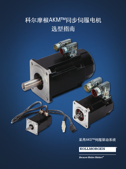
K O L L M O R G E N | A K o l l m o r g e n C O M PA N Y欢迎来到科尔摩根官方微信科尔摩根3目录u AKM ™ 同步伺服电机4u AKD ™ 伺服驱动器8u AKM ™ 各种选件12u AKM ™ 防水型和食品级防水型电机13u AKM ™ 系统综述14u AKM ™ 图纸和性能数据AKM1x 16AKM2x 20AKM3x24AKM4x 28AKM5x 34AKM6x 40AKM7x 44AKM8x48u L 10 轴承疲劳寿命和轴负载53u 反馈选件56u 抱闸选件60u 伺服电机连接器选件61u 型号命名67u MOTIONEERING ® Online71科尔摩根A K M 同步伺服电机选型指南克服设计、采购和时间障碍科尔摩根明白:帮助原始设备制造商的工程师克服障碍,可以显著提高其工作成效。
因而,我们主要通过如下三种方式来提供帮助:集成标准和定制产品在很多情况下,理想方案都不是一成不变的。
我们拥有专业应用知识,可以根据全面的产品组合来修改标准产品或开发全定制解决方案,从而为设计奠定良好的基础。
提供运动控制解决方案而不仅仅是部件在各公司减少供应商数量和工程人力的过程中,他们需要一家能够提供多种集成解决方案的全系统供应商。
科尔摩根就采用了全面响应模式,为客户提供全套解决方案,这些方案将编程软件、工程服务以及同类优秀的运动控制部件结合起来。
覆盖全球我们在美洲、欧洲、中东和亚洲拥有众多直销、工程支持单位、生产工厂以及分销商,临近全球各地的原始设备制造商。
这种便利优势可以加速我们的供货过程,根据客户需要随时随地供货。
财务和运营稳定性科尔摩根隶属于Fortive 公司。
Fortive 业务系统是推动Fortive 各部门发展的一个关键力量。
该系统采用“不断改善”(Kaizen )原理。
由高素质人才构成的多学科团队使用世界级的工具对过程进行评估,并制定相关计划以达到卓越的性能。
- 1、下载文档前请自行甄别文档内容的完整性,平台不提供额外的编辑、内容补充、找答案等附加服务。
- 2、"仅部分预览"的文档,不可在线预览部分如存在完整性等问题,可反馈申请退款(可完整预览的文档不适用该条件!)。
- 3、如文档侵犯您的权益,请联系客服反馈,我们会尽快为您处理(人工客服工作时间:9:00-18:30)。
Use and Maintenance ManualforThree-phase Synchronous Motor Dalian Yulin Electric Motor Co., Ltd.1. OverviewThis manual provides the instructions and guidance on the receipt, storage, installation, operation and maintenance of a synchronous motor.Only when the installation, operation and maintenance are performed in strict accordance with the requirements of the manual, can the long-term, safe and reliable use of the motor can be ensured.1.1Main components of motorThe main components of the motor are: stator, rotor, rolling bearing, end cap, terminal box, chassis, slip ring, etc.1.2Meaning of sign code1.2.1 Ingress protectionDepending on installation location and use conditions, the types of protection for the motor enclosure include IP23 and IP44.1.2.2 Cooling methodThe sign of cooling method consists of characterization letters "IC" and the subsequent characterization numbers and letters. This series is IC01, self-cooling open-type, with a fan mounted on the shaft.1.3 Terminal of stator and rotor1.3.1 The wire terminals of three-phase winding of synchronous motor stator use U, V, W and N as the signs and use N as the ground terminal.1.3.2 The initial and final terminals of winding of synchronous motor rotor (magnetic field) use F1 and F2 as the signs.1.4 Rotation directionThe rotation direction of synchronous motor is clockwise looking from the drive end.2. Installation2.1 Packing and deliveryThe packing for the motor shall adopt unit packing. For this reason, the user should refer to the outline drawing to determine the content receiving, verify that the receipt is complete, and inspect that the box has signs of damage.If the box is indeed defective or damaged, please notify the manufacturer’s business sector in severe cases. Preferably in the presence of representatives of the transport sector, open the damaged box for check. If the motor body is found to have damage, the necessary testing and repair should be conducted according to the damage degree prior to installation. Meanwhile, the motor nameplate must be stated with the relevant data, including model, power, voltage, speed, production number and date of manufacture and so on.2.2 Lifting and handling2.2.1 The slings must be used, so that the motor can be lifted via lifting bar, lifting hole or boom.2.2.2 When the entire motor is lifted, the weight distribution must be appropriate.2.3 Storage informationThe motor should be stored in a clean and dry place and be covered. If the place is kept cold, wet or humidity-variable, and the temperature of the motor winding should be several degrees higher than the ambient temperature, in order to avoid dew condensation or damping. During long-term storage, the electric heater on the motor can be electrified to get rid of moisture insidethe motor.Preferably, the insulation resistance shall be measured once every month to test the protective effect of storage. When there are significant changes in insulation resistance, indicating the cause is damping. Now, you should consider improving the storage conditions.2.4 Preparation before installation2.4.1 UnboxingRemove all packaging, clean away anti-rust oil and dirt with petroleum solvent, and comply with necessary safety precautions.2.4.2At the installation site, check all the items in the packing list of the motor. If you receivethe parts and components are missing or the equipment is damaged, you should immediately notify the manufacturer.2.4.3On the base frame, the location marker shall be determined to identify the center line andof the unit and the elevation of the base surface.2.4.4According to the outline drawing, the foundation shall be verified to determine that the pit,ventilation pipes, cables and tubing position is correct, and there is enough space for the installation of the unit and its accessories.2.4.5According to the outline drawing, the size and location of foundation bolt hole, and theelevation on the top of bolt.2.5Selection of installation locationWhile deciding where to install the motor, you should consider the following factors:2.5.1 Environmental conditions for the installation of the motor:a. Altitude of not more than 1000m;b. Ambient air temperature of not exceeding 40 ℃;c. The monthly average maximum relative humidity of ambient air in the wettest month is 90%, while the monthly average minimum temperature is not higher than 25 ℃.In case of failure to meet the above three requirements, special orders shall be needed, which will be indicated in special technical conditions.2.5.2 The motor shall be installed in a well ventilated place, and the air inlet and outlet on the motor shall be kept in appropriate positions, in order to prevent the exhaust hot air from entering the air inlet, resulting in repeated cycles, or prevent the hot air exhausted from a motor from directly entering another motor.2.5.3 There should be sufficient space around the motor to disassemble, clean, or check the motor.2.6 Foundation2.6.1 The foundation must be rigid, and the resulting vibration shall be reduced.2.6.2 The motor foot (or chassis side) must be placed on the base plate. The top surface of the base plate shall be a horizontal plane, and its elevation shall be slightly lower than the maximum size of the distance from the motor shaft centerline to the foot (or chassis side).2.7 GroutingThe clean sand and cement shall be mixed at the mixing ratio of 1: 1, and be mixed with water into slurry; the slurry shall be thin enough to fully fill the underside of the chassis or the base plate. The entire operation process of slurry mixing and pouring shall be as fast as possible without interruption. The slurry shall fill all the structural space of the chassis or the base, and be perfused to flush with the top surface of the chassis or the base plate.2.8 Adjustment of mounting surface2.8.1 The adjustment shims shall be made of the thin steel plates with different thicknesses, the width and length shall be slightly greater than the foot size (those with the chassis are not subject to this limit), and a gap or hole shall be provided to get out of the foundation bolts.2.8.2 After the adjustment in the direction of height, plugging shall be performed using the shims with the thickness used for measurement.2.8.3Upon the final alignment of axis, the shims shall adopt a small quantity of thick shims, instead of a large quantity of thin shims. In general, multiple shims with the thickness of 1.5mm and above shall be replaced by the single shim with the equal thickness. After the final alignment the center, the positioning pin hole shall be drilled and shorn, and then be installed with the positioning pins.2.8.4 In case the drive end of the motor needs to be installed with coupling, hammering shall be prohibited, in order to prevent the shaft from withstanding the impact.3. Operation Instructions3.1 Preparation before operation3.1.1 Inspect that the voltage, frequency, phase, etc on the motor nameplate are consistent with the parameters of power supply.3.1.2 Measure the insulation resistance of motor winding. For the minimum allowable value, see4.4.1. If necessary, dry it.3.1.3Inspect that the stator (armature) lead and power line signs of the motor to determine whether the motor rotation direction meet the requirements.3.1.4Inspect that the connections of motor control, protection and monitoring devices are in compliance with the specifications and the corresponding drawings.3.1.5 Inspection of slip ring and carbon brushThe carbon brush shall be able to move freely up and down in the carbon brush box, and the carbon brush shall maintain a certain pressure.3.1.6 Inspect for any foreign objects left in the motor, and use appropriate hand tools to move the rotor disk, and inspect for rubbing sound.3.2 Commissioning of motor3.2.1 It is recommended that the commissioning of synchronous motor should be conducted in the case of failure to butt the supporting machine.3.2.2 Verification of rotation directionFor the synchronous motor, inspect the correctness of the rotation direction in the way of post-electrification inching (press start control button, then immediately press the shutdown control button).3.2.3 Rotate the motor again to timely inspect the temperature of the bearing.3.2.4 For the allowable temperature of the bearing, see4.1.2.3.4 Startup and shutdown of synchronous motor3.4.1 For the salient-pole synchronous motor with slip ring, start-up resistance shall be connected in series within the loop of rotor (magnetic field) winding upon start-up, and start-up resistor element resistance, current and other parameters shall be consistent with the electrical documents.3.4.2 Start-up duty of synchronous motor3.4.3.1 When the initial state of the motor is the ambient temperature, the second consecutive start shall be allowed.3.4.3.2 When the initial state of the motor is rated operating temperature, only once start shall be allowed.3.4.3.3Only after an interval of 1-3 hours, can re-start-up be conducted according to Section 3.4.3.1 and Section 3.4.3.2.The start-up time interval stated in this section depends on the heat capacity and cooling conditions of start winding. In principle, the start-up winding shall be cooled to ambient temperature before re-start-up.3.4.4 Start-up mode of synchronous motor3.4.4.1 Direct start-up, i.e. the terminal of stator (armature) winding is connected directly to the power supply.3.4.4.2 Undervoltage start-up, i.e. during start-up, the terminal of stator (armature) winding is connected to the power supply via the reactor (or auto-transformer, heat rheostat). The start-up voltage upon undervoltage start-up shall be determined based on the motor parameters, in order to avoid the motor damage caused by overheating during start-up.3.4.5 Start-up of synchronous motor after electrification, i.e. after the motor is synchronized, the excitation current shall be adjusted to meet the need of the load.3.4.6 Shutdown of synchronous motor3.4.6.1 Turn-on of motor power switch.3.4.6.2 Input of start-up resistance, this will play the role of resistance de-excitation.3.4.6.3 Stop of auxiliary equipment (fuel pumps, water pumps, blowers, etc.).4 Maintenance and repairThrough regular periodic inspection, you can discover defects, in order to eliminate hidden dangers and prevent the occurrence of faults, and improve operational reliability.4.1 Temperature rise limit and allowable temperature of motor4.1.1 For the temperature rise limits of motor, see Table 6.4.1.2 Allowable temperature of motor bearing:Rolling bearing (at the ambient temperature of not exceeding 40 ℃) is 95 ℃.4.2 Monitoring for temperature of motor4.2.1 For the monitoring setting values (initial value) of Class B insulation and Class F insulation4.2.2 If the operating temperature values are known, then:Alarm value = operating temperature +5 ℃ Tripping value = operating temperature +10 ℃4.2.3 Normal operating temperature often changes with the ambient temperature; the setting value shall be adjusted according to the ambient temperatures in different seasons. 4.3 Vibration limits of motora. At the rated speed of 600r/min and above, the vibration limit of motor shall be 2.8mm / s; b At the rated speed of 600r/min below, the double-amplitude limit of motor shall be 0.075mm.4.4 Insulation resistance of motor4.4.1 Minimum allowable values of winding insulation resistance:a. At the ambient air temperature: 1MΩ/kV;b. In the hot state (under operating conditions):=1000+100UR PWhere: R- insulation resistance of motor winding, MΩ; U- rated voltage of motor winding, V;P - rated power of motor, kW; rated power of generator, kV A.4.4.2 At the ambient air temperature, the minimum allowable value of insulation resistance of embedded temperature detectors : 1MΩ4.4.3 At the ambient air temperature, the minimum allowable value of insulation resistance of insulation bearing:a. Newly installed motor: 1MΩ;b. After r egular overhaul: 0.3MΩ. 4.5 Drying of motorIf the insulation resistance value of motor winding is less than the minimum allowable value, heating and drying shall be performed to remove moisture.4.6 Maintenance and repair of stator (armature) winding and the rotor (magnetic field) windingIn order to fully examine and clean the motor, the rotor must be pulled from the stator.According to the degree and condition of accumulation of dust on the winding, you can clean the motor with the following method. 4.6.1 Wipe-dryWhen the surface that needs to be cleaned is just covered with dust, use a clean lint-free cloth to wipe it dry, but you can not use a waste cloth.4.6.2 BlowingSome gaps inside the motor, which are difficult to reach shall be blown with clean and dry compressed air (pressure less than 0.2MPa), in such a direction that the dust can not be brought deeper into the motor.4.6.3Solvent cleaning methodFor the removal of fat, dirt, wax, oil, etc from the winding, solvent cleaning method is particularly effective. A cloth moistened with mild detergent solution shall be used to wipe the surface, and then it shall be wiped with a dry cloth.4.7 Maintenance and repair of bearing4.7.1 Maintenance and repair of rolling bearingRolling bearing is the standard replaceable part.The grease grade used for rolling bearing shall comply with the standard requirements. The grease has a finite life, and under the influence of mechanical stress and chemical aging, it has gradually lost its lubricating properties. Therefore, it needs to be regularly replaced.For the allowable temperature of rolling bearing, see 4.1.2, so that the grease can achieve the expected normal life.4.7.2Replacement of lubricantGenerally, 50g lubricant shall be injected once a month, and complete replacement shall be conducted once a year. However, this depends largely on the running time, operating temperature and the degree of oil contamination. In case of severe turbidity or sudden rise in temperature without external influence, the lubricant shall be replaced.4.8Maintenance and repair of slip ring ring and carbon brush4.8.1 The surface of slip ring shall be kept smooth and cylindrical. After a period of running, slip ring contact surface will form a layer of oxide film containing graphite, and the surface film may be in color between light gray and black, depending on carbon brush grades, current density, air temperature and humidity.When the surface of slip ring is not smooth, but is covered with rust and burn marks, the fine sand paper can be used for grinding.4.8.2To make two rings be worn uniformly, their polarities need to be replaced once to twice within one year.4.8.3 During the running of motor, it is normal that the carbon brush wear is less than 6mm/1000 hours. When the carbon brush is worn too much, you should also get a new carbon brush. The grade of the new carbon brush must be the same as that of the original carbon brush. The contact surface between the new carbon brush and the slip ring shall be machined into the arc that is the same as the radius of slip ring, in order to ensure the good contact between the carbon brush and the slip ring.4.8.4On the insulation between the slip ring and the carbon brush holder, the extent of accumulation of dust shall be regularly checked and the dust shall be cleared away, preferably by removing the toner with a vacuum cleaner, and blowing with compressed air, and finally wiping with a clean dry cloth.4.9 Routine inspection of motor during running4.9.1 Measure the stator (armature) winding temperature, bearing temperature, inlet and outlet airtemperature, analyze the records, and inspect that there is abnormal situation.4.9.2 Inspect that the motor has unusual mechanical noise or the changing sound (such as friction or percussion sound, etc.).4.9.3Vibration measurement, the measuring point can be selected in the middle of the bearing chamber.4.9.4Inspection of lubrication system, including the oil level of bearing, the rotation state and oil-bring extent of slip ring, any oil spills and discoloring of lubricant, etc.4.10 Regular shutdown maintenance period of motorThe regular shutdown maintenance period of motor shall be based on site conditions and type of the motor structure, typically be in accordance with the following deadlines:a.Motor overhaul: once a year;b.Motor repair: 2-4 times per year.5 Motor failure analysis5.1 Possible failure of synchronous motor5.1.1 During start-up, due to the too low supply voltage, the motor can not rotate.The decrease rate of the motor start-up torque is proportional to the square of the voltage drop. If the decreased start-up torque is less than the load resistance torque, the motor will not rotate.5.1.2During start-up, the motor has magnetic noise, but the rotor does not rotate, with obviousvibration.This may be because the motor is started after being supplied with the excitation current. Now, the excitation status of the excitation device shall be inspected.5.1.3 During start-up, the motor gives normal magnetic noise, but the rotor does not rotate.This may be because the load torque is too large, or the increase in load is more than the motor start-up torque due to a failure of dragged machine.5.1.4 During start-up, the junction of damping ring sparks.Usually, the connecting bolts are not tightened, or the junction of damping ring has bad contact.5.1.5 The motor fails to be frequently started in accordance with the requirements of Section 3.4.3, so overheating is caused to the start-up winding, resulting in unsoldering or breaking of damping bar.5.1.6 During start-up, due to the low supply voltage and insufficient torque, the speed can not be increased to 95-97% of rated speed, resulting in non-pull-in synchronization.5.1.7 The setting range of excitation part of excitation device can also cause non-pull-in synchronization.5.1.8 Slip ring flash or singeing, mainly due to:5.1.9 The cylindrical coaxiality of slip ring is not good, or the surface of slip ring is rough.5.1.10 The grade of the carbon brush is inappropriate, or the pressure on the carbon brush is too small, which hinders the carbon brush from sliding because of being tightly packed in the carbon brush box.。