Koch-Glitsch FLEXITRAY 塔盘样本
ASPENPLUS理论考试答案
ASPEN PLUS 培训理论考试一、填空题:(每题3分 共48分)1、在精馏塔的模拟计算中用(芬斯克方程)求最小平衡级数(全回流)、用(恩德伍德方程)求最小回流比(平衡级数无穷大)、利用(吉利兰关联式)求出在一定回流比时对应的平衡级数;2、物性模型分为:⑴、理想、状态方程(EOS)模型,写出其中常用的两个PENG-ROB 、RK-SOAVE ,该模型用到范德华方程,其表达式为:(P+a/V 2)(V-b) = RT c c P T R a 642722= cc P RT b 8= ⑵、活度系数模型,写出其中常用的三个NRTL 、UNIFAC 、UNIQUAC ,3、特殊模型, 如要处理液相中的轻气体或超临界组分,需要采用亨利定律。
3、对于物性方法的选择,要知道物系的理想行为是指符合理想气体定律和拉乌尔定律;想物系是指大小和形状相似的非极性组分;非理想程度是指分子相互作用,例如,分子的大小、形状和极性;而选择物性方法的基本原则:考虑因素包括物系中是否有极性组分,操作条件是否在临界区,体系中有无轻气体或超临界组分等;4、应用亨利定律的步骤分为:定义亨利组分、调用亨利参数、在物性定义表选择亨利组分。
5、在做板式塔的设计计算时,需要提供计算范围、塔板类型、液流数、直径、板间距;同时也要运用到其约束条件,主要包括液泛因子、起泡因子、过设计分数等;6、在精馏塔RADFRAC 严格核算模型,对于塔的收敛算法有三种,主要是外循环即计算相平衡、中循环即计算设计规定、内循环即计算质量、能量平衡。
而计算塔的收敛技巧主要有:检查所给的操作条件是否确实合理、增加迭代次数、增加进料闪蒸计算次数、增加计算的阻尼性、改变算法。
7、精馏塔的水力学计算包括: ①塔板类型:Glitsch BALLAST 、Koch Flexitray 、Nutter Floatlve 、Bubble Cap 、Sieve 。
②填料类型;③板式塔的设计计算;④填料塔的设计计算; ⑤板式塔的核算;⑥填料塔的核算;⑦冷凝器/再沸器曲线。
KG-TOWER精馏塔模拟软件入门

I NTRODUCTION TO KG-TOWER®T ray & Packed Tower Sizing Software ProgramV ersion 2.0Visit our website at L OADING INPUT SCREEN1.Vapor and Liquid Rates: Enter internal vapor and liquid rates from process simulation output.Densities are required inputs. Enter either mass rates or volumetric rates and the other value will be calculated based on the density.If the gas density in not known, it can be estimated using the gas density calculation module by pressing the “Calc” button. Vapor viscosity, liquid viscosity, and liquid surface tension are optional inputs. The values tend to have a much greater impact on the packing hydraulic calculations than tray calculations and should be entered when known. If no value is entered, these values will be estimated using a correlation derived for hydrocarbon systems.The input units can be changed by using the “Units” menu. The loading conditions in each column can be copied, deleted, or scaled by using the “Edit” menu.---- CONFIDENTIAL ----The information contained herein is the confidential and proprietary property of Koch-Glitsch and is not to be copied, reproduced or disclosed to others in whole or in part without prior written consent of Koch-Glitsch. THERE ARE NO WARRANTIES, EXPRESSED OR IMPLIED, INCLUDING BUT NOT LIMITED TO, WARRANTIES OF MERCHANTABILITY OR---- CONFIDENTIAL ----The information contained herein is the confidential and proprietary property of Koch-Glitsch and is not to be copied,reproduced or disclosed to others in whole or in part without prior written consent of Koch-Glitsch. THERE ARE NO WARRANTIES, EXPRESSED OR IMPLIED, INCLUDING BUT NOT LIMITED TO, WARRANTIES OF MERCHANTABILITY OR 2. System Factor : Enter a system factor to derate the tray capacity ratings for foaming or other factors if necessary. For trayed columns, the system factor is used to derate both the jet flood and downcomer flood ratings.Severity of foaming can be dependent on a number of different factors and operating experience is the best method for determining the exact system factor for a particular system. Typical system factors used for trayed columns are shown in table 1. These same system factors may not be applicable for use in derating packed column capacity. Consult with your local Koch-Glitsch representative for assistance in selecting the appropriate derating factors for packed systems.Table 1: Typical System Factors for Trayed TowersSYSTEM SYSTEM FACTOR Absorbers (over 0o F)0.85Absorbers (under 0o F)0.80Amine Contactor0.80Vacuum Towers0.85Amine Stills (Amine Regenerator)0.85Furfural Fractionator0.85High Pressure Hydrocarbon Fractionators (Demethanizers& Deethanizers)0.85Glycol Contactors0.60Glycol Stills &Glycol Contactors in Glycol Synthesis Gas0.65C02 Absorber0.80C02 Regenerator0.85Caustic Wash0.65Caustic Regenerator, Foul Water, Sour Water Stripper0.60Alcohol Synthesis Absorber0.35Hot Carbonate Contactor0.85Hot Carbonate Regenerator0.90Oil Reclaimer 0.70---- CONFIDENTIAL ----The information contained herein is the confidential and proprietary property of Koch-Glitsch and is not to be copied,reproduced or disclosed to others in whole or in part without prior written consent of Koch-Glitsch. THERE ARE NO WARRANTIES, EXPRESSED OR IMPLIED, INCLUDING BUT NOT LIMITED TO, WARRANTIES OF MERCHANTABILITY ORTRAY DESIGN SCREEN3. Tray Type : KG-TOWER software can be used to provide detailed calculations for Valve, Bi-FRAC ®, or MAX-FRAC ® trays. Selection of TRITON ®, Nye, SUPERFRAC ® or ULTRA-FRAC ® trays will take the user directly to the Tray Results screen for a display ofapproximate jet flood and pressure drop parameters. Tray ratings of Koch-Glitsch’s other high performance tray – the SUPERFLUX ® tray – are not currently available in the KG-TOWER software.Proper tray selection can be complex. In many cases, there may be more than one tray type suitable for a particular application, thus making tray selection difficult for engineers who are not tray design experts. In such cases selection is often based on previous application experiences or ease of mechanical revamp. Consult with your local Koch-Glitsch representative if you need assistance with proper tray selection.4. Tower Diameter: The column diameter input units can be set for feet, inches, millimeters ormeters by selection of “Custom” under the “Units” pull-down menu.When sizing new columns, the tower diameter may be estimated using the tools menu. This will require some specification of the number of passes, tray spacing, and design flooding values.Caution should be used when rating tray columns with column diameters less than2.5 ft [762 mm] as these trays may require special mechanical tray construction (cartridge /post supported trays with envelope downcomers) that may not be accurately accounted for using KG-TOWER software.5. Number of Passes: Select one, two, three or four flow passes. The number of flow passesshould be increased as required to provide the necessary liquid handling capacity. When sizing new columns, it is generally desirable to utilize the minimum number of flow passes necessary to meet the capacity requirements as this will result in the highest tray efficiency, greatest operating flexibility, and the lowest cost.In some cases, the column diameter may limit the number of flow passes practical in order to avoid the use of trays with very short flow path lengths or trays than can not be designed for man access through the trays.Table 2: Minimum Tower Diameter Required For Multipass TraysNo of Passes Min Tower ID2 5 ft [1524 mm]38 ft [2438 mm]410 ft [3048 mm]6. Valve Type Select the valve type from the menu. A photo of each valve type can be obtainedby clicking on the small photo next to the valve type.The type ‘A’ valve (equivalent to Glitsch V-1 BALLAST® Unit) is recommended for general purpose use. The VG-10 valve is the recommended conventional fixed valve. Its large size and net rise make it particularly suited for dirty or corrosive services. The VG-0 fixedMINIVALVE® valve and the PROVALVE® valve have been added since the previousversion.---- CONFIDENTIAL ----The information contained herein is the confidential and proprietary property of Koch-Glitsch and is not to be copied, reproduced or disclosed to others in whole or in part without prior written consent of Koch-Glitsch. THERE ARE NO WARRANTIES, EXPRESSED OR IMPLIED, INCLUDING BUT NOT LIMITED TO, WARRANTIES OF MERCHANTABILITY OR---- CONFIDENTIAL ----The information contained herein is the confidential and proprietary property of Koch-Glitsch and is not to be copied,reproduced or disclosed to others in whole or in part without prior written consent of Koch-Glitsch. THERE ARE NO WARRANTIES, EXPRESSED OR IMPLIED, INCLUDING BUT NOT LIMITED TO, WARRANTIES OF MERCHANTABILITY OR 7. Valve Quantity, Valve Density, and Open Area : Enter either the number of valves per tray,the number of valves per square foot of active area, or the tray open area and the remaining two values will be calculated.For valve trays, the open area is defined as the smaller of either the horizontal hole area punched in the deck of the trays or the vertical slot/escape area from the valves. Tray open areas typically range from 5 to 14%.For VG-10 fixed valves, the slot height of the valve opening is variable and must be provided by the user (indicated as the net rise). A good starting point for the net rise of a VG-10 valve is 10 mm.Table 3: Typical Valve Densities for Fully Valved TraysConventional Type A (V-1) and Type T ValvesTower Diameter Single PassValves/ft2[Valves/m2]Two Pass Valves/ft2[Valves/m2]Three & Four Pass Valves/ft2[Valves/m2]2.5 - 4.5 ft [762-1372 mm]10.0 [108]--5 – 6 ft [1524 –1829 mm]12.0 [129]10.0 [108]-6.5 – 7.5 ft [1981-2286 mm]13.5 [145]12.0 [129]-8 – 10 ft [2438 –3048 mm]14.0 [151]13.0 [140]-10.5 – 12 ft [3200-3658 mm]14.0 [151]13.5 [145]12.0 [129]12 ft + [3658mm +]14.0 [151]14.0 [145]12.0 [129]8. TRAY DETAILS : The tray details button is used primarily to provide additional information on the valve units and valve layout. For most preliminary design purposes, the default values can be utilized to given adequate estimations of performance. These values may be provided for cases when more detailed design estimates are preferred or when rating existing tray designs.The details button includes specification of the valve leg length (or cage height), tray thickness, valve thickness, and valve material.Of the mechanical details inputs – manway ID, support ring width, and envelope width - are more critical when used in evaluating high performance tray designs.9.TRAY GEOMETRY:Downcomer widths (top and bottom), weir heights, downcomerclearances, and tray spacings must be provided or estimated to complete the traycalculations. Additional tray features such as weir blocks (or picket fence weirs), swept back weirs, radius-tip downcomers, recessed inlet sumps, and inlet weirs are also supported with KG-TOWER software and may be input when applicable. For clarification on the meaning of these provided variables, select the ‘sketch’ button to see a pictorial view of theseparameters.When sizing new columns, preliminary downcomer sizes can be estimated using the tools menu.Proper definition of tray geometry requires some experience to ensure that the design is not only optimized from the process standpoint, but also to ensure that it is mechanicallyfeasible to convert the design on the computer into real metal (for example, is it possible to fit this number of valve units on the tray panels? Or, does this tray design have long enough flow paths to allow for tray manways?, etc). Several detailed tray design guidelines exist that are outside the scope of this training session. Consult your local Koch-Glitschrepresentative for detailed reviews and evaluations of equipment designs.---- CONFIDENTIAL ----The information contained herein is the confidential and proprietary property of Koch-Glitsch and is not to be copied, reproduced or disclosed to others in whole or in part without prior written consent of Koch-Glitsch. THERE ARE NO WARRANTIES, EXPRESSED OR IMPLIED, INCLUDING BUT NOT LIMITED TO, WARRANTIES OF MERCHANTABILITY ORTRAY RESULTS SCREEN9.Jet Flood: Jet flood rating should be limited to 85% of flood to avoid the possibility offlooding and/or inefficient operation. Increasing tower diameter, active area and/or tray spacing can be used to reduce the jet flood rating.10.Downcomer Flood: Downcomer rating should be limited to 85% of flood. The downcomerrating is generally set by the size of the downcomer area at the top. For a well balanced tray design, the downcomer and jet flood ratings should be fairly equal.---- CONFIDENTIAL ----The information contained herein is the confidential and proprietary property of Koch-Glitsch and is not to be copied, reproduced or disclosed to others in whole or in part without prior written consent of Koch-Glitsch. THERE ARE NO WARRANTIES, EXPRESSED OR IMPLIED, INCLUDING BUT NOT LIMITED TO, WARRANTIES OF MERCHANTABILITY OR11.Downcomer Backup: The clear liquid downcomer backup is reported in both inchesof liquid and as a percentage of the tray spacing plus weir height. The clear liquid backup should be limited to 40% of the tray spacing plus weir height for normal services. For high pressure, light hydrocarbon distillation services, the clear liquid backup should be limited to 30-33% of the tray spacing plus weir height. The downcomer backup is dependent on the tray pressure drop and the clearance underthe downcomer.12.DC Exit Velocity: The downcomer exit velocity is the liquid velocity as it flows horizontallythrough the downcomer clearance. This value should be limited to 1.5 ft/sec [0.46 m/s] for conventional valve tray designs. The downcomer exit velocity is most easily adjusted by changing the downcomer clearance.13.Dry Tray DP: The dry tray pressure drop is an intermediate term in calculating the total traypressure drop that does not include the effect of the liquid head. It can be used to provide a relative indication of vapor velocity through the valves. A good starting point for many tray designs is a dry tray pressure drop of around 2 inches of hot liquid. As a rule of thumb, the dry tray pressure drop should be limited to 15% of the tray spacing when possible.14.Total Tray DP: Many tray design methods do not set specific limits on the tray pressuredrop; however, a tray typically reaches flood at a pressure drop of around 8-10 mm Hg per tray. The tray pressure drop is also a very key component to downcomer hydraulics due to its impact on downcomer backup.Note: Consistent with industry standards, the total tray pressure drop calculated byKG-TOWER software is comprised solely of the dry tray drop and the hydrostatic head of liquid that exists on the tray when liquid is flowing across it. The KG-TOWER software-calculated total tray pressure drop does not include the vapor static head in the operating column (i.e. the weight of the vapor is excluded from the calculation). Vapor static head must be estimated by process engineers responsible for the total distillation system including the heat exchangers. Vapor static head can have an appreciable impact on the pressure difference between the top and the bottom of a distillation column. For example, in a demethanizer witha vapor density of 5 lb/ft3 and 24-inch tray spacings, the inclusion of the vapor static headcan cause the calculated top-to-bottom pressure difference to double.15.Cf, Active Area: C f or capacity factor is a commonly used, density-corrected vapor velocityterm on a per unit of active area basis.---- CONFIDENTIAL ----The information contained herein is the confidential and proprietary property of Koch-Glitsch and is not to be copied, reproduced or disclosed to others in whole or in part without prior written consent of Koch-Glitsch. THERE ARE NO WARRANTIES, EXPRESSED OR IMPLIED, INCLUDING BUT NOT LIMITED TO, WARRANTIES OF MERCHANTABILITY OR16.Weir Load: The weir loading is generally used to determine the liquid loading of thetray. Although there is no specific design limit for weir loading, increased number offlow passes should be considered when the weir loading is greater than 100 – 120 gpm/ft[74.5 – 89.4 m3/h/m] in order to provide increased tray capacity. Trays have been designed insome large-tray-spacing cases with weir loadings greater than 200 gpm/ft [149 m3/h/m];however, consultation with a Koch-Glitsch design engineer is recommended when designing trays for weir loadings greater than 140 gpm/ft [104.3 m3/h/m].A minimum weir loading of 5 gpm/ft [3.7 m3/h/m] is recommended at turndown. Picketfence outlet weirs (or "weir blocks") can be added to increase the weir loading by specifying an override to the calculated outlet weir length or specifying a percentage of the outlet weir to be blocked.17.Crest: The crest is the theoretical height of clear liquid flowing over the outlet weir. It isimportant to remember that the liquid leaving the tray consists of drops, spray and slugs and not a measurable height of clear liquid as this term might suggest.The liquid crest is directly associated with the weir loading. A minimum liquid crest of 0.25 inches [6 mm] is recommended to ensure proper tray performance at low liquid rates.18.Head Loss Under DC: The head loss under the downcomer is based on the downcomerclearance and the shape of the downcomer edge. Typically, the head loss should be designed somewhere between 0.06 to 1.0 inches [1.5 to 25 mm]. The head loss can be adjusted by changing the downcomer clearance or utilizing radius-tip downcomers.19.DC Residence Time: The calculated residence time in the limiting downcomer is based on theliquid flow rate and the available volume of the downcomer. Downcomer residence time is not typically used by Koch-Glitsch to determine proper downcomer sizing; however, this parameter is used by some tray designers to size downcomers in foaming systems.20.Blow Rating: The blow rating indicates the approach to a phase inversion condition, in whichthe liquid is blown into a fine spray (or "fluidized"), leaving the trayessentially dry (even though the spray is not necessarily carried to the tray above).The result is a loss of column efficiency due to gas bypassing and a shift in the limiting mass transfer resistance (from the gas side to the liquid side).The blow rating is only applicable to trays operating in the spray regime and thus is reported as zero for moderate to high liquid rate applications.---- CONFIDENTIAL ----The information contained herein is the confidential and proprietary property of Koch-Glitsch and is not to be copied, reproduced or disclosed to others in whole or in part without prior written consent of Koch-Glitsch. THERE ARE NO WARRANTIES, EXPRESSED OR IMPLIED, INCLUDING BUT NOT LIMITED TO, WARRANTIES OF MERCHANTABILITY ORThe blow rating should be held to a maximum of to 85% if possible. It can be reduced by increasing the number of valves, adding weir blocks, and/or raising the outlet weir height. 21.System Limit: The system limit represents an ultimate column capacity limit which can not beexceeded by changing the tray design or increasing the tray spacing. It occurs when there is substantial up-flow of liquid entrained relative to the total liquid flow and is a function of the droplet sizes created at a certain surface tension and the terminal velocities of the liquid droplets as determined by Stokes Law.22.Turndown: The turndown is an approximation of the minimum vapor rate required forefficient tray activity (vapor and liquid contacting from movable valve units), expressed as a percent of the loads specified. This term applies only to moveable valves (not fixed valves) and is not to be confused with weepage .If possible, valve trays should be designed for a turndown percentage of at least 50% atdesign rates (allowing a 2:1 turndown from the design rates). For the minimum rate cases, the calculated turndown percentage should be less than or equal to 100%.23.Unit Reference: Unit reference is the percentage of valves open at a given operatingcondition. This term serves a similar function of the turndown percentage (#24) and isapplicable to only moving valve units. The suggested minimum unit references are given in table 4.Table 4: Recommended Minimum Unit ReferenceNumber of Flow Passes Minimum Unit Reference140260370480If the unit reference is less than the minimum recommended, the valve quantity should be reduced or consideration should be given to the use of two weights of valves.26. Equation 13: Equation 13 is the conventional valve tray jet flood capacity modelfrom Glitsch Bulletin 4900. It is reported as a convenience to those users that arefamiliar with this popular flooding model.---- CONFIDENTIAL ----The information contained herein is the confidential and proprietary property of Koch-Glitsch and is not to be copied, reproduced or disclosed to others in whole or in part without prior written consent of Koch-Glitsch. THERE ARE NO WARRANTIES, EXPRESSED OR IMPLIED, INCLUDING BUT NOT LIMITED TO, WARRANTIES OF MERCHANTABILITY ORPACKED TOWER DESIGN SCREENa. Scale Factors: Scale factors are used to provide quick adjustment of the vapor and liquidloadings. The vapor and liquid loads can be scaled independently by checking the ‘separate’scale factor box.b.Packing Type: Select from a range of Koch-Glitsch random, structured, or grid packings. Thefull line of Norton packings are not yet available in the program although more have been added since Version 1.0.---- CONFIDENTIAL ----The information contained herein is the confidential and proprietary property of Koch-Glitsch and is not to be copied, reproduced or disclosed to others in whole or in part without prior written consent of Koch-Glitsch. THERE ARE NO WARRANTIES, EXPRESSED OR IMPLIED, INCLUDING BUT NOT LIMITED TO, WARRANTIES OF MERCHANTABILITY ORc.Tower Diameter: Input the inside diameter of the column. It is important to account for anylining, clad, or wall thickness – especially when rating very small packed columns.When sizing a new column, it is also possible to enter the desired packing flood capacity and have the program calculate the required column diameter (for a given packing size).d.Flood, Constant L/V%: The calculated percentage of flood (based on a constant liquid/vaporratio) should be limited to 80% for most cases. For those systems where the liquid rate is held constant, the flooding percentage may be reported on a constant liquid rate basis by selecting ‘flooding limit’ under the options menu.e.Fs, Cv, and Liquid Load: These terms are used to provide a relative indication of the vaporand liquid loads in the tower. These are based on the total cross sectional area of the tower.No general design guidelines exists for these parameters; however, some specific guidelines are used for certain packings and/or for specific applications based on commercialexperience.f.Pressure Drop: The packing pressure drop is expressed per unit of vertical distance (feet ormeter) of packing height. Again, packing and application specific guidelines are used to determine minimum and maximum acceptable pressure drop limits.Please note that the pressure drop in packed towers should also take into account the pressure drop across the packed bed internals (distributors, collectors, etc) which are not accounted for in the packing pressure drop. In addition, the packing pressure does not include the vapor static head of vapor (see item #15 under tray hydraulic calculations for additional details).---- CONFIDENTIAL ----The information contained herein is the confidential and proprietary property of Koch-Glitsch and is not to be copied, reproduced or disclosed to others in whole or in part without prior written consent of Koch-Glitsch. THERE ARE NO WARRANTIES, EXPRESSED OR IMPLIED, INCLUDING BUT NOT LIMITED TO, WARRANTIES OF MERCHANTABILITY ORK G-TOWER® SoftwareL icense Agreement (“Agreement”)Upon agreement with these terms as evidenced by your choice of the “I AGREE” option below, Koch-Glitsch, LP and/or its affiliates (“Koch-Glitsch”) grants you a personal, non-exclusive, non-transferable, royalty-free license to use the KG-TOWER® software (“Software”). This License shall remain in effect until terminated by Koch-Glitsch or until automatic termination, which will occur upon the end of the license agreement or the violation of any of these provisions. The Software is the property of Koch-Glitsch and all rights to patents, copyrights, trademarks and trade secrets in the Software or any modification are, and shall be without limitation, the property of Koch-Glitsch. Modification, alteration, translation, disassembling or creation of derivative materials is strictly prohibited. Proprietary and/or copyright notices or labels will not be removed for any reason. Koch-Glitsch provides the Software “AS IS” and offers no warranty or guarantee of any kind as to the information provided in the Software, including but in no way limited to results arising from the use of the Software, the accuracy of the information derived from the Software, or for any other use, non-use or application of the Software, and you acknowledge and agree that you assume all liability under any and all applicable laws in connection with your installation and use of the Software. THERE ARE NO WARRANTIES, EXPRESSED OR IMPLIED, INCLUDING BUT NOT LIMITED TO, WARRANTIES OF MERCHANTABILITY OR FITNESS FOR A PARTICULAR PURPOSE ASSOCIATED WITH THE INSTALLATION, OPERATION OR OTHER USE OF THE SOFTWARE. Koch-Glitsch shall have the right to modify the terms of this License or the Software at any time without notice. IN NO EVENT SHALL KOCH-GLITSCH BE LIABLE FOR ANY LOSS, DAMAGE, CLAIM, FINE, PENALTY OR ANY OTHER CLAIM, INCLUDING BUT NOT LIMITED TO CLAIMS FOR CONSEQUENTIAL, SPECIAL, GENERAL, INCIDENTAL, DIRECT, INDIRECT, PERSONAL INJURY OR PROPERTY DAMAGES, INCLUDING WITHOUT LIMIT LOSS OF PROFITS, REVENUES, OR OTHER ECONOMIC LOSSES, ARISING FROM OR IN ANY WAY CONNECTED TO THE INSTALLATION, OPERATION OR USE OF THE SOFTWARE. This License shall be governed by the Laws of the State of Kansas, and any dispute or claim pursuant to this License shall be subject to the exclusive jurisdiction of the courts located in Wichita, Kansas, USA.KG-TOWER®, Bi-FRAC®, MAX-FRAC®, TRITON®, SUPERFRAC®, ULTRA-FRAC®, SUPERFLUX®, and KOCH-GLITSCH® are registered trademarks of Koch-Glitsch, LP.---- CONFIDENTIAL ----The information contained herein is the confidential and proprietary property of Koch-Glitsch and is not to be copied, reproduced or disclosed to others in whole or in part without prior written consent of Koch-Glitsch. THERE ARE NO WARRANTIES, EXPRESSED OR IMPLIED, INCLUDING BUT NOT LIMITED TO, WARRANTIES OF MERCHANTABILITY OR。
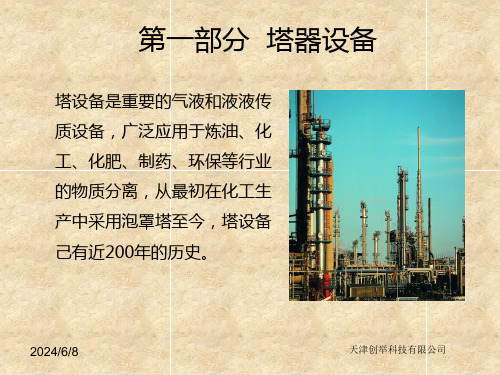
第二课塔器设计基础及案例
Ring
Intalox Saddle
螺旋环,Spiral Ring
改 进 矩 鞍 (Glitsch) ,
Ballast Saddle
鲍尔(开孔)环,
改 进 矩 鞍 (Koch) , Flexi
Pall (Slotted)Ring
Saddle
哈埃派克(Norton)Hy-Pak 改
进
矩
鞍
(Hydronyl)Hydronyl
体在管内停留时间短,不容易结垢,且容易清洗;但壳程不能清洗,因此用 于较脏的加热介质;其本身造价较低,但要求较高的塔体裙座.
• 卧式热虹吸再沸器的主要特点:可用低裙座,但占地面积大,出塔
产品缓冲容积较大,故流动稳定,在加热段停留时间短,不容易结垢,可以 使用较脏的加热介质.
• 立式和卧式强制循环再沸器的共同特点:适应于高粘度液体和
热敏性物料,因为强制循环流速高,停留时间短,有利于工艺流体循环流 量的控制和调节.
精馏方案的选定
• 5.冷却方式
– 1)冷却剂----通常是水,水温随气候而定.入口一般为15℃--20℃,出
口<50℃,目的防止溶解于水中的无机盐析出.
• 冷却剂 还可以是冷冻盐水.液氨等,一般用于较低温度。
– 2)冷凝设备的结构形式
2024/6/8
4
天津创举科技有限公司
➢ 六七十年代,出现塔径十米以上的板式塔,塔板 数多达上百块、塔高度达80米;填料塔的最大直 径有15米,高八十年代以后,填料塔开始大量应用。板式塔与
填料塔的应用并驾驱,竞争日趋激烈。 ➢ 近年来,大量新型塔板研究成功。例如:
• 小塔---蛇管换热器 • 大塔---列管式换热器
工艺流程设计的要求
填料塔盘名称中英文对照

塔Column板式塔和填料塔Plate Column and Packed Column1. Plate column (tray column) 板式塔2. davit吊杆3. vapour outlet 蒸气出口4. demister破沫网5. vent放空口6. reflux inlet回流口7. tray塔盘,塔板8. manhole人孔9. support ring (保温)支承圈10. reboiler return重沸器(物料)返回口11. thermometer connection温度计接口12. vortex (vortex breaker, anti – ca vita tion baffle)破涡流器,防涡流板13. skirt vent裙座放气口14. skirt裙座,塔裙15. access hole出入孔16. base ring底圈,底环17. ladder直梯,梯子18. liquid outlet 液体出口19. level gauge connection液面计接口20. pressure gauge connection压力计接口21. feed inlet进料口22. platform平台23. down comer (downflow, downspout) 降液管,降液板24. packed column填料塔25. gas outlet气体出口26. liquid distributor液体分配器,液体分布器27. hold – down grid格栅式填料压板28. packing填料29. packing support plate填料支持板30. liquid redistributor液体再分布器31. handhole手孔32. gas inlet气体入口33. liquid inlet液体入口塔板词汇之液流型式1. cross flow横流2. reverse flow折流,U型流3. radical flow径流4. circumferential flow环流5. split flow(double pass)双流6. cascade阶梯流7. double pass cascade双阶梯流8. four pass四流9. inlet downcomer入口降液管10. outlet downcomer出口降液管11. baffle折流檔板12. side downcomer侧面降液管13. center downcomer中间降液管14. intermediate weir中间堰15. inlet weir入口堰16. outlet weir出口堰17. recessed seal pan(凹)受液盘18. tray塔盘,塔板19. straight downcomer直降液板20. tapered downcomer斜降液板21. circular downcomer(圆形)降液管塔板词汇之泡罩(帽)塔盘1. circular cap tray圆泡罩塔盘2. bubble cap (bell cap)泡罩3. riser (vapor riser, upcomer, chimney)升气管4. slot齿缝5. down comer降液管6. tunnel cap (rectangular cap)槽形泡罩7. uniflux tray S形塔盘,单流向式塔盘8. “S”member S形(塔盘)组件9. flat bubble cap扁平泡罩10. vaned bubble cap带导向叶片的圆泡罩11. open slot开口齿缝12. closed slot闭口齿缝13. set on riser外套式升气管14. swaged riser内插式升气管15. pull up riser穿插式升气管16. bolt or stud hold down cap螺栓(或双头螺柱)压紧式泡罩17. wedge hold down cap楔紧式泡罩18. quarter turn cap卡口式泡罩塔板词汇之浮阀塔盘1. Nutter float valve tray纳特条形浮阀塔盘2. deck(floor)板3. P(plain) type Nutter float valve P(平面)型纳特条形浮阀4. D (dimpled) type Nutter float valve D(点接触)型纳特条形浮阀5. L (louvered) type Nutter float valve L (直通)型纳特条形浮阀6. DL (dimpled and louvered) type Nutter float valve DL(点接触和直通)型纳特条形浮阀7. F (full cover) type Nutter float valve F(全覆盖)型纳特条形浮阀8. Chepos valve tray切普斯条形浮阀(穿流)塔盘9. Glitsch ballast valve tray格利奇重盘式浮阀塔盘10. Downcomer降液管19. K2a slat valve-sieve tray K2a长条形筛孔浮阀塔盘20. K2a slat valve K2a长条形(筛孔)浮阀21. T type flexitray (fle xible tray)T型盘式浮阀塔盘22. A type flexitray (fle xible tray)A型盘式浮阀塔盘23. cross flow valve tray错流式浮阀塔盘24. pipe valve tray管式浮阀塔盘25. pipe support管式浮阀支架26. pipe valve管式浮阀,管阀27. H y – contact valve锥心浮阀28. Float valve – sieve tray浮阀-筛孔塔盘29. Glitsch combined valve and sieve tray格利奇浮阀-筛孔混合塔盘30. overflow weir溢流堰31. hole(筛)孔32. Turbo – float tray (TFT)波纹浮动塔盘33. cross element横条34. seal damper可调降液板35. tray element塔盘浮动组件,浮动角钢36. stopper限位板37. support bar支持杆38. seal pan受液盘39. gird – valve tray链网式浮阀塔盘40. Speichim float valve方形浮阀塔板词汇之筛板塔盘1. sieve tray (perforated tray)筛板塔盘2. hole筛孔3. sieve (perforated) tray with downcomer 有降液管的筛板塔盘4. downcomer降液管5. Turbogrid with downcomer有降液管的波纹式栅板(塔盘)6. Linde sieve tray林德筛板塔盘7. directional slot导向孔8. Hagbarth tray塔外降液管式泡罩-筛板塔盘9. sieve plate筛板10. cap泡罩11. West tray韦斯特筛板-槽形泡罩塔盘12. tunnel cap槽形泡罩,条形泡罩13. modified sieve type tray改型筛板塔盘14. expanded metal 多孔拉制金属网板15. subsupport angle ring辅助角钢圈16. weir溢流堰17. major beam主梁18. minor beam支梁19. minor beam support clamp支梁卡子20. support ring支持圈21. manway通道22. M – D (multipe downcomer) sieve tray 多降液管筛板塔盘塔板词汇之穿流式塔盘和喷射型塔盘1. Turbogrid tray波纹型穿流(淋降)栅板塔盘2. ripple tray波纹筛板塔盘3. arrangement of float valve and hole 浮阀和筛孔的排列形式4. slotted tray条形浮阀穿流塔盘5. K1 type slat valve K1型条形浮阀6. dual – flow float valve穿流浮阀7. jet tray喷射型塔盘8. tab舌片9. directional float tray浮舌塔盘,浮动舌形塔盘10. Perform tray定向孔塔盘11. stream breaker碎流挡板12. inlet weir入口堰13. downcomer降液管14. seal pan受液盘15. expanded metal多孔拉制金属网板16. Venturi tray文丘里塔盘17. standard Kittel plate条孔网状塔盘,基特尔标准式塔盘18. lower plate下板19. upper plate上板20. cascade tray阶梯式塔盘塔盘的支承1. package tray整装式塔盘2. handhole手孔3. cartridge tray整节塔盘4. spacer定距管5. rod拉杆6. packing填料7. downcomer降液管,降液板8. tower wall塔壁9. separated tray分块式塔盘10. manway cover plate通道,盖板11. weep hole泪孔,滴水孔12. weir溢流堰13. tray floor塔板,塔盘板14. bubble cap泡罩15. support ring支持圈16. support beam支承梁17. downcomer bar降液板连接板18. screw螺钉19. washer垫圈20. clip卡子21. gasket垫片22. overlap type搭接自身梁式(塔盘)23. flanged type折边自身梁式(塔盘)24. beam support type梁支承式(塔盘)25. angle truss (minor beam)角钢支梁26. trapezoidal truss (minor beam)梯形钢支梁27. channel truss (minor beam)槽钢支梁28. backing strip垫板29. irregular gasket异形垫板填料的形式有拉西环、鲍尔环、波纹填料、蜂窝填料、鞍形填料、丝网填料、环矩鞍形填料、阶梯环型填料、格栅型填料Packing types: Raschig ring, Pall ring, Gauze packing, Beehive packing, Saddle packing, Metal wire mesh packing, Intalox saddle packing, Cascade mini ring, Grid packin g常用的塔盘有圆泡罩塔盘、舌形塔盘、S形塔盘、筛板塔盘、浮阀塔盘、浮动喷射式塔盘、混合型塔盘等。
FLEXTRAY 产品说明书

27
77
53
39
30
58
49
42
36
93
77
60
46
94
78
61
47
119
83
61
47
119
83
61
47
119
83
61
47
119
83
61
47
128
89
65
50
128
89
65
50
111
77
57
43
124
86
63
48
128
89
65
50
128
89
65
50
141
98
72
55
154
107
78
60
Cable Fill (50% fill)**
Actual Area Inside Number of CAT Number of
Tray (in2)
5e Cables*** CAT 6 Cables***
12.2
4.3 8.2 12.1 16.1
23.9 31.8 35.8 39.7
47.5 59.8 63.3
15.8 23.6 31.5 47.5 63.5
*** CAT 5e 4-pr non-plenum approximated at .21 in. diameter, CAT 6 4-pr non-plenum approximated at .25 in. diameter. Actual diameters vary by cable manufacturer.
MD 塔盘

• 90° tray rotation • Shorter flow path • No bolting bars
16
MD Tray Assembly
• Simple design and construction, supported by 360° ring • Downcomers function as primary structural support • No need for bolting bars or center beams • Results in faster tray installation
MD Tray Features & Benefits
Features • No seal pans • More downcomers • Longer weir length Benefits Fully active tray area, High vapor capacity High liquid capacity Low froth height & tray spacing, Low pressure drop (40%↓)
Unit Cell
12
UOP - CONFIDENTIAL
C3 Splitter Large Diameter Experience
uop C3 Splitter Experience (Partial Large Diameter List)
Location *161* *159* *158* 157 *149* 148 *147* *142* 140 *123* *117* *108* *92* Thailand India Saudi Arabia Saudi Arabia Saudi Arabia Saudi Arabia Saudi Arabia India Taiwan Saudi Arabia Spain Malaysia India No. of Trays 208 MD 188 ECMD 225 MD 145 ECMD 200 MD 266 MD 205 MD 188 MD 287 MD 200 MD 205 MD 208 MD 188 MD Purity 99.5 99.5 99.6 98.1 99.6 99.6 99.5 99.5 99.8 99.56 99.5 99.5 99.5 Pressure bar a 12.8 7.9 12.7 7.9 5.69 21.1 12.5 12.0 18.17 5.69 12.00 12.8 12.0 Diameter mm 7300 7500 7600 8300 8000 10100/8600 7800 7500 8200/7000 8000 7800 7300 7500 Spacing mm 380 365/375 400/380 400 380/400 425/435/500 360/380 365/376 380/400 380/400 360/380 380 365/375 Year 2006 2006 2006 2006 2005 2005 2005 2004 2004 2001 2000 1998 1996 Type G G G G G G G G G G G G G
分离塔KGTOWER文件4

VALVE TRAY RATING DATARegistered To: 人查干, 推荐KG-TOWER? Software v 5.1Customer's copy.Property of Koch-Glitsch.Strictly confidential.Project Name 03-七月-2013Tower Name Case Name PO 分离塔T0101操作压强1.1MPaDate :By :Revision :V-star File :T0101-PO 分离塔.kgt Page :4/ 4提馏段提馏段提馏段DESCRIPTION 68MIN MAX TRAY NUMBER ZONE% OF LOADING 11090100cP Vapor Viscosity Liquid Viscosity cP LOADINGS 448.97367.34408.16mN/mm3/hr Surface Tension Liquid Volume 762.38762.38762.38kg/hr 342285280051311168Liquid Density 23.9019.5521.73m3/s Vapor Volume Liquid Rate 1.1771.1771.177kg/m3Vapor Density 1012908287492082kg/hr Vapor Rate 0.01160.01160.011630.480.3280.3280.32830.4830.48kg/m3|||80.0080.00mm Weir Height0.721.180.450.56Downcomer Area m2||||||||||190.00310.00316.00366.00mm Downcomer Width ||||||BOTTOM TOP ||||||CenterTOP Side800.00800.00800.00mm Tray Spacing |||75.0075.00mm Downcomer Clearance|||9.261420Est. Number of Valves1.001.001.00System Factor 0.3960.3240.360245.9200.6221.0m/s mm liq Downcomer Exit Velocity Downcomer Backup%635257806572%Jet Floodm2Active Area4484mm Weir Length Type A(V-1)Valve Typemm 1429Flow Path Length m2211.34Tower Area 3800mm Number of Passes Tower Diameter 61.053.457.3mm liqWeir Crest100.181.991.0m3/h/m Weir Load 0.100.080.09m/s Cf Active Area 8.36.67.4mm Hg Total Tray Pressure Drop 148.3117.5131.5Total Tray Pressure Drop mm liq 74.050.0Dry Tray Pressure Drop mm liq 61.4Downcomer Flood |BOTTOMActive AreaPanel APanel BFlow Path Length m2mm4.751439.00 4.631429.00The information contained herein is the confidential and proprietary property of Koch-Glitsch, LP and/or its affiliates ("Koch-Glitsch"). This information and any derivatives thereof are the exclusive property of Koch-Glitsch. This information is believed to be accurate and reliable but is not to be construed as implying any warranty or guarantee of performance. The KG-TOWER(TM) Software that generated this report may not be used by or exportedor re-exported to any U.S. embargoed country (currently Cuba, Iran, Syria, Sudan, and North Korea), a national or resident of such countries, or anyone on the U.S. Treasury Department's list of Specially Designated Nationals. You are solely responsible for compliance with U.S. economic and trade sanctions. Refer to the License Agreement for additional information.。
托盘和塔填料类型

ASPEN plus 塔盘类型汉英对照
1、塔盘类型:Bubble Cap 泡罩
Sieve 筛板塔盘
Glitsch Ballast 栅扳塔盘
koch Flexitray 柯赫浮阀塔盘
Nutter Float Valve 条状浮阀
2、填料类型:BERL 贝尔鞍,弧鞍填料
BX萨尔泽尔锌基bx规整填料
CMR 波纹环
COIL 环形填料
FLEXERA 柯赫曲线填料
FLEXIGRID 柯赫栅格填料
FLEXIMAX 柯赫高性能不规整填料
FLEXIPAC 柯赫柔性波纹板填料
FLEXIRING 柯赫单面环槽不规整填料
FLEXISADDL 柯赫鞍形不规整填料
H CKP 柯赫多面槽环形不规整填料
HELI 螺旋填料
HELIX 螺旋角填料
I-BALL I-球型填料
IMTP 氧化铝基金属填料
INTX鞍形氧化铝填料
ISP 莫顿规整填料
LESCHIG 浸环
MCMAHON McMahon 填料MELLAPAK 萨尔泽尔锌基蜂窝规整填料MESH筛网环形填料
PALL 鲍尔环
SNO WFLAKE 氧化铝基雪片状塑料填料SUPER-INTX高级氧化铝基鞍形填料。
- 1、下载文档前请自行甄别文档内容的完整性,平台不提供额外的编辑、内容补充、找答案等附加服务。
- 2、"仅部分预览"的文档,不可在线预览部分如存在完整性等问题,可反馈申请退款(可完整预览的文档不适用该条件!)。
- 3、如文档侵犯您的权益,请联系客服反馈,我们会尽快为您处理(人工客服工作时间:9:00-18:30)。
FLEXITRA Y ® Valve TraysProven performance in all liquid-vapor contacting applications.FLEXITRAY ® valve trays combine high capacity and excellent efficiency with a wide operating range. Utilizing proprietary design techniques and the wide range of valve types available for FLEXITRAY valve trays, design engineers at Koch-Glitsch have the knowledge and experience to assist you in optimizing performance for your application.With Koch-Glitsch technical expertise in design, manufacturing, and installation, a well-designed FLEXITRAY valve tray generally provides the most economically attractive solution for grass-roots column construction projects.Cost effectiveThe initial purchase price, simple installation, and reduced maintenance of the FLEXITRAY valve tray contribute to cost effective projects.Versatile An existing tower equipped with FLEXITRAY valve trays can often be used in a different application with minimum modifications because of the wide operating range, high capacity, low pressure drop, and excellentefficiency.Conventional trays are equipped with standard downcomers. The typical inlet areas under the downcomer and a bubbling area can be customized using a variety of valve types depending on the application or service.With these product advantages plus Koch-Glitsch technical expertise, KOCH-GLITSCH ® conventional trays have been installed in tens of thousands of plants worldwide. Year after year, they continue to be the trays preferred by plant operators.Benefits of FLEXITRA Y Valve TraysUniform vapor distribution, wide operating rangeb Excellent liquid-vapor contacting for high efficiencyb Reduction of the reflux ratio for a given tower diameterb Smaller tower diameter for a given feed rateThe vapor exiting a valve is directed horizontally, rather than vertically as in a sieve tray, reducing entrainment. This also allows longer run times in fouling services because horizontal radial vapor flow at the tray floor reduces “dead spots” where solids can settle, polymer growth can start, or decomposition can occur.Higher capacity and low pressure drop FLEXITRAY valve trays can handle loadings up to 10% higher than sieve trays while providing higher efficiency. The contoured hole of the T0 type valve provides the lowest pressure drop per tray over a wide range of flow rates.Valve TypesKoch-Glitsch has the valve type for your application/service.Koch-Glitsch has developed a variety of valve styles to enhance the vapor-liquid contacting that takes place on a tray deck.A- Full-size, one-piece valve■ Higher capacity than standard sieve trays■ High efficiency■ Wide operating range ■ Low pressure drop■Cost effectiveT- Full-size caged valve■ All the advantages of Type A valvesPlus:■ More weepageresistance – even wideroperating range■ Increased foulingresistance – fewer costlyshutdowns■ Rugged construction – resistant to corrosionand erosion■FRI tested This is the standard, round, full-size, one-piece valve that has been used successfully in columns around the world for over 50 years.b It is provided in several leg lengthsto accommodate various tray deckthicknesses.b It is normally dimpled to helpprevent sticking to the deck, but canbe flush seated if needed.b The orifice can be made to preventthe valve from spinning.b Dual valve weights may be used inalternating rows to extend thealready wide operating range. Equivalent BALLAST® designation: V-1.Type T is the caged equivalent to the Type A valve. The use of this FRI(SM)-tested valve precedes the Type A valve.b The Type T valve has a single movingcap with no moving legs protrudingthrough the deck.b A cage assembly retains the cap.b It is more resistant to weeping and tobecoming dislodged from the deck.b It is more fouling resistant than theType A valve.b It normally comes dimpled, but canbe flush seated as necessary. Equivalent BALLAST® designation: A-2.T0- Full-size, low pressure drop valve■ Same as a Type T valve Except:■ Contoured hole in the deck for lowest possiblepressure drop This variation of the Type T valve uses an extruded, Venturi-like orifice.b The dry tray pressure drop is thuslowered, providing an overall lowerpressure drop.b This comes with a price of higherweepage and reduced turndown. Equivalent BALLAST®designation: A-5.VG-10- Full-size fixed valve■ Large opening size for improved foulingresistance■ Extended time between shutdowns■ Fixed opening means the valve cannot stickshut like moving valves■ Easy to clean – lessdowntime■ Rugged, durableconstruction for longtray life■ Can be made frommaterials up to 0.25”(6.35 mm) thick formaximum resistance tocorrosion This is a full-size fixed valve that is anything but conventional.b The net rise typically ranges from 6 mm[0.236 in] to 14 mm [0.551 in], varying in 1 mm[0.039 in] increments. Other lifts may beavailable in some cases.b This valve is also directional with the rear legbeing visibly wider than the downstreamfront leg.b As with any fixed valve, it can never becomestuck to the deck nor can it spin.b The large net rises available plus the directionalliquid flow make this an outstandinganti-fouling valve. It is widely used onanti-fouling SUPERFLUX® trays.– Using a large net rise ensures that largeparticles can freely pass through the deckopenings.– There are no protrusions below the deck forany material to hang up on and for deposits.– The liquid push is strong enough to helpsolid material to be flushed downstreamand toward the downcomer where it canexit off the tray deck.MINIV AL VE®decksThe MINIV ALVE® family of smaller-size valves provide reduced entrainment and better efficiency than conventional valve and sieve trays.The improvement in capacity can exceed 13% in spray regime services with low-to-moderate weir loadings. MINIVALVE® valves exhibit a more uniform froth action on the tray deck compared to full-size valves. They are offered in both fixed (VG-0) and moveable (MV-1) styles.MINIVALVE valves are directional with the rear leg being a little wider than the downstream front leg. This gives a slight pushing action to the liquid as vapor passes through the valves.The liquid push assists in maintaining a more uniform flow pattern on crossflow trays with less retrograde action. It also helps offset vapor crossflow channeling effects to a small degree.VG-0- MINIV ALVE® fixed valve■ Higher capacity than full-size valve trays –smaller tower or morethroughput■ High efficiency – fewer trays or less refluxrequired■ Fixed opening – valve cannot stick shut■ Formerly used onSUPERFRAC® tray decksonly■ FRI tested■ Cost effective■ U.S. Patent No. 5,147,584This widely-used, fixed, high-performance valve has been tested at FRI on two different sets of high capacity trays.b The net rise can range from as low as4 mm [0.158 in] to as high as 11 mm[0.433 in]. Recommended rises vary withdeck thickness and the nature of the service.b A fixed valve can never become stuck to thedeck nor can it spin.b The VG-0 valve’s fouling resistance is quitegood. In fact, it has been used in a numberof fouling applications on the decks of highperformance, anti-fouling SUPERFLUX®trays.b The operating range is quite good, exceedingthat of a sieve tray and almost matching that of moving valves. This valve is replacingfull-size, conventional moving valves inmany installations.MV-1- MINIV ALVE® moving valve■ Higher capacity than full-size valve trays –smaller tower or morethroughput■ High efficiency – fewer trays or less refluxrequired■ Formerly restricted toSUPERFRAC® tray decks ■ Wide operating range ■ U.S. Patent No. 5,120,474Originally used only on SUPERFRAC®high-performance trays, this moving valve is now available for use on conventional trays. This valve offers high capacity and efficiency AND a wide operating range.Because of the way the legs are inserted into the deck, the valves cannot spin. The valves come in two leg lengths, although the longer length is rarely needed – the shorter leg accommodates most common deck thicknesses.Valves are normally furnished dimpled with tabs to space the cap edges slightly off the deck. A flush-seated style is available upon request.PROV ALVE®fixed valve■ Higher capacity thanfull-size valve trays■ Maximum opening size for maximum foulingresistance and freepassage■ Longest up timebetween shutdowns■ Fixed opening means the valve cannot stick shutlike moving valves■ High weepage resistance for a wide operatingrange■ Easy to clean – lessdowntime■ Rugged, durableconstruction forlong tray life■ Low pressure drop■ FRI tested■ U.S. Patent No. 5,762,834The PROVALVE valve offers the wide operating range of conventional valve trays, but with no moving parts. The valve design prevents valve leg or deck wear and eliminates the potential for popped, fouled, or stuck valves.b The tapered cover imparts a forwardlateral push to the liquid across thetray, allows a large open area, anddirects and deflects the vapor.b The result is uniform liquid andvapor distribution across the entiretray with a low, even spray heightacross the deck. This increases thetray’s efficiency, prevents liquidbackflow, suppresses jet flooding, and permits operating at greater vaporrates.b The cleansing action from the liquidpush protects the tray deck fromfouling.b In addition, the sheltered valvedesign allows a large open areathat promotes lower pressure dropand protects against vapor surges.Other Conventional Trays from Koch-Glitsch Koch-Glitsch has the broadest line of tray devices available in the industry. From conventional trays to high performance trays, Koch-Glitsch has the right tray for your application:■Sieve■Bubble cap■Tunnel■Dualflow■BaffleHigh Performance Trays from Koch-GlitschFor decades, Koch-Glitsch has been the driving force in tray design improvements. Koch-Glitsch’s design and manufacture of distillation trays have evolved from bubble cap to sieve to valve trays and now to specialty, high-capacity trays. The patented technologies used in SUPERFRAC® and ULTRA-FRAC® trays are the result of over twenty years of comprehensive tray development work.b For new columns, Koch-Glitsch high-capacity trays can be employed to reduce diameters, heights, or both.b For existing columns, they can replace existing trays to increase capacities, reduce utilities, or improve separations.b In total, our high-capacity trays have been employed in over 1,000 columns.SUPERFRAC® High Performance TraysThe SUPERFRAC® tray is a high performance crossflow tray that has the highest combined capacity and efficiency of all crossflow trays tested at FRI.The unique combination of SUPERFRAC patented technologies anddesign strategies produces the high capacity and the maximumvapor/liquid contact efficiency achieveable on a crossflow distillationtray.These technologically advanced trays employ innovative downcomerdesigns and enhancements in the active and inlet areas to provide:b Highest combined capacity and efficiencyb Minimal pressure dropb Optimum mass transfer efficiencyAs a result, the SUPERFRAC tray gives the highest economic benefitto operators of distillation columns seeking solutions for both newconstruction and revamp projects.ULTRA-FRAC® High Performance TraysExpand your capacity — not your vessel.The ULTRA-FRAC® tray is the next logical step to increased capacityin existing vessels:b Highest capacity commercial mass transfer deviceb Multiple separators produce co-current flowWith these trays, existing columns can be retrofitted, resulting insignificant capacity increases without the major capital expendituresand space requirements of building new columns. One-for-onechange-outs of existing trays are possible for many services.ULTRA-FRAC trays offer:b Superior liquid handlingb Superior vapor handlingb Foam suppressionConstruction DetailsMetalTrays are available in any formable, weldable sheet metal material. The most common materials for trays are:b Carbon steelb Stainless steel, Ferritic, Austenitic, Duplex, Martensitic b Nickel alloysb Copper alloysb Titanium, ZirconiumTrays are not normally stress relieved or annealed and typically do not conform to pressure vessel standards. Trays fabricated from sheet metal materials are typically supplied in “as-sheared” condition.BoltingStandard bolting conforms to AISI specifications. Bolting conforming to ASME® specifications is available upon request.CertificationMaterial certification is available for all fabricated internals. Positive Material Identification (PMI) testing is available upon request.GasketingFor multi-piece trays requiring gasketed joints, many choices of gasket material are available. Where gasketing is required, braided fiberglass tape is supplied as the standard for linear joints. Depending on the service, KLINGERSIL® C-4401, expanded PTFE or spiral wound stainless steel with flexible graphite filler gaskets are supplied as the standard for flanged connections. Other gasket materials are available upon request.Manway AccessAll trays are designed in sections to pass through vessel manways. Tower internals are designed to pass through a vessel manway of 18 in [450 mm] minimum inside diameter, unless otherwise specified. Larger manways often provide the ability to optimize the design of components for faster, easier installation. Please provide manway locations and inside diameters at the time of inquiry.Scope of SupplyFor the trays in this brochure, Koch-Glitsch supplies all removable parts.The trays do not include vessel attachments for connection or support, unless specifically stated in the item description. Vessel attachments may be quoted/supplied separately. Examples of attachments that may be required are:b Support ringsb Sump framesb Internal flanges at feed inlet nozzlesb Wall clips for supportb Downcomer clamping barsb Beam seatsFeed DevicesObtaining desired tower performance requires the proper handling of liquid and vapor entering the column. The types of feeds or inlets into a column can generally be classified into three major categories:b Liquid only (contains less than 1%of vapor by volume)b Mixed liquid and vapor, flashing orsuppressed flashb VaporThe selection criteria for each category of feed device is unique.Liquid-Only Feeds Among the factors that Koch-Glitsch engineers consider when designing a liquid feed device are:b Type of trayb Expected tray performanceb Flow rateb Operating rangeb Degree of sub-cooled liquidb Requirements for mixingThe feed arrangement for these conditions depends on the tray type. Please consult with a Koch-Glitsch technical representative for recommendations.Liquid-Vapor and Flashing FeedsFor mixed liquid-vapor or flashing feed devices above a tray, the selection depends on:b Tray typeb Liquid and vapor flow ratesb Turndownb Column height needed fordisengagement and vapordistributionb Requirements for mixingIn all cases, separating the vapor and the liquid phases is a primary concern. In some cases, the requirements for additional pre-distribution may alter Vapor-Only FeedsTwo factors must be considered whenchoosing the proper device for avapor-only feed.b The kinetic energy of the inlet vaporin relation to the pressure dropacross the trays, the feed nozzlearrangement, and the towerseparation requirements.b If there is a large difference in thecomposition and/or temperaturebetween the inlet vapor stream andbulk vapor flow, mixing the twovapors optimizes the performanceof the trays.Specific equipment for vapordistribution may not be required ifsufficient column height is available forequalization or if the pressure dropacross the trays is sufficient to provideproper vapor distribution.CFD ModelingGood vapor distribution is essential toachieve superior separation efficiency.Poor vapor distribution is often a majorsource of problems.Koch-Glitsch combines modernComputational Fluid Dynamics (CFD)modeling technology with itsengineering expertise to analyze vaporand liquid distribution when evaluatingthe performance of existing equipmentand developing new, improved designs.This involves computer modeling of the3-dimensional configuration of thecolumn internals to provide detailedpredictions of fluid flow (velocityprofiles and so forth) as shown in thefigure below.Koch-Glitsch offers CFD services for thefollowing tasks:b Development and optimization ofnew mass transfer equipmentb Troubleshooting or analysis ofexisting equipmentb Confirmation of equipment designsprior to fabrication and installationMechanical FeaturesFLEXILOCK ® Tray ConstructionThe patented FLEXILOCK tray joint allows rapid installation of tray panels in vessel shops or in the field. FLEXILOCK tray construction eliminates the requirement for hardware between adjacent tray panels and provides for error-free deck installation.FLEXILOCK tray construction can be used to:bReduce hardware requirements bImprove valve coverage bProvide error-free deck installation bDramatically reduce installation time bStrengthen joint and uplift tolerance bPromote in-shop installationsbCancel vibration-induced panel shiftingOMNI-FIT ® Technology OMNI-FIT technology is a set of mechanical engineering designs used to reduce the cost and downtime of revamps. These technologies include expansion rings, pedestal supports, downcomer adapters, and innovative tray designs that can minimize or eliminate welding on an existing tower. Efficiency and capacity enhancements can be achieved by using OMNI-FIT technology for your next turnaround project.OMNI-FIT technology can be used to:bIncrease theoretical stages bChange tray spacings bChange the number of passes bModify downcomer sizes or configurations bInstall multi-pass SUPERFRAC trays bChange tray orientation bEliminate welding bShorten turnarounds bReplace packing b And more…HORIZON ® TechnologyHORIZON technology is a set of mechanical construction techniques developed specifically for in-shop installation of trays with the vessel in the horizontal position. Using the patented FLEXILOCK tray construction as its primary building block, this special mechanical design prevents the problems that can occur when conventionally designed trays are installed with the vessel in the horizontal position.These problems include inefficient installation sequencing, part deforming/breaking, panel shifting, joint dislodging, extra field inspecting and field readjusting of tray parts. If you plan to shop-install trays, then you need theassurance provided by HORIZON technology.Before After10Mechanical FeaturesSATURN ® TechnologyThe patented SATURN technology can reduce the total installed cost of newdistillation columns with its combination of innovative tray designs and simple tower attachments.When crossflow trays are used, conventional designs use horizontal ring segments to support tray decks and vertical bolting bars to support traydowncomers. With the SATURN technology, all of the crossflow tray parts are supported from the horizontal ring.SATURN technology brings together:b The high efficiency, high capacity, low cost, and reliability of crossflow trays bThe simple rings of dual-flow traysSPEED-WA Y ® ManwaysAt last, a design that allows you to easily add quick-openingmanways to your existing trays. Just remove the existing manway or active panels and replace them with SPEED-WAY panels.These quick-opening manways are especially beneficial when:b Turnaround manpower is limited b Short downtime is critical bRoutine inspections are requiredIf you have a need to tunnel through your column on a routine basis,SPEED-WAY manways are a must.Why do this?When you cando THIS?Tray Maintenance ServicesComprehensive services for turnarounds and shutdowns.Koch-Glitsch provides comprehensive services to help you reduce costs and shorten scheduled turnarounds and emergency shutdowns for maintenance.Our Response Teams are strategically located around the world and are ready to serve you at any time.Services include:b Inspectionb Hardware trailers and lockersb Automated Hardware Ordering Program (AHOP)bEquipment Support Services (ESS) techniciansEmergency DeliveryEmergencies happen . . .Koch-Glitsch has a wide variety of tray products to provide optimum performance whatever your application. Many common materials are in stock and trays can be quickly manufactured to get you back on line.For emergencies, call the Hotline of your nearest Koch-Glitsch office:b In the US, call the Hotline at 1-888-KOCH-911.bIn Europe, call +44-1782-744561, +39-06-928-911,or your local Koch-Glitsch office.Koch-Glitsch Corporate OfficesWorldwide HeadquartersKoch-Glitsch, LP4111 East 37th Street North Wichita, KS 67220 – United States tel: (316) 828-5110 fax: (316) 828-7985EuropeKoch-Glitsch Italia S.r.l.Viale Giulio Cesare 29 24124 Bergamo – Italy tel: +39 035 2273.411 fax: +39 035 2273.400AsiaKoch-Glitsch Korea, Ltd.17-8, 8F, Dongsung Bldg.Yoido-dong, Youngdeungpo-kuSeoul 150-874 – Korea tel: +82-2-3276-7500 fax: +82-2-3276-7590 Koch-Glitsch (A division of Koch Chemical Technology Group India Pvt. Ltd).Corporate Park II, 10th FloorSion-Trombay RoadChembur, Mumbai 400 071 – India tel: +91 22 6771 7171 fax: +91 22 6771 7161 For a complete list of our offices and facilities, visit us on the Web at .Emergency NumbersUS: 1-888-KOCH-911.Europe: +39-06-928-911, +44-1782-744561, or your local Koch-Glitsch office.Asia Pacific: Contact your local Koch-Glitsch office.TrademarksBALLAST, FLEXITRAY, HORIZON, KOCH-GLITSCH, “K” KOCH-GLITSCH, MINIVALVE, OMNI-FIT, PROVALVE, SUPERFLUX, SUPERFRAC, and ULTRA-FRAC are registered trademarks of Koch-Glitsch, LP and are registered in the US and various countries worldwide. FLEXILOCK is a trademark of Koch-Glitsch, LP and is registered in the US. SATURN and SPEED-WAY are trademarks of Koch-Glitsch, LP and are registered in various countries worldwide. All other trademarks, service marks, or registered trademarks that appear in this document are the trademarks or service marks of their respective owners. PatentsFLEXILOCK, PROVALVE, SATURN, and SPEED-WAY technologies are protected by various patents worldwide.Legal NoticeThe information contained in this bulletin is believed to be accurate and reliable, but is not to be construed as implying any warranty or guarantee of performance.Bulletin FTCVT-01. Rev. 6-2010. Printed in U.S.A.© 2007-2010. Koch-Glitsch, LP. All rights reserved.。