33K3-4-3484-1 Network Analyzer E5061A, E5062A, E5070B
KLEA Network Analyzer Energy Analyzer 使用手册说明书

K L E AEnergy AnalyzerManual操作手冊手冊目錄章節 1 產品資訊 (10)1.1警告標示 (10)1.2 注意事項 (10)1.3 收貨與清點注意事項 (11)1.4 KLEA 電力分析錶 (11)1.5 KleaCom軟體 (12)1.6 KLEA 前面版資訊 (13)章節 2 安裝程序 (15)2.1 安裝前準備事項 (15)2.2嵌入安裝 (15)2.3 接線圖 (19)2.3.1 三相四線 (3P4W) (19)2.3.2 三相三線 (3P3W) (20)2.3.3 三相Aron接線 (20)2.4產品尺寸 (21)章節 3 選單 (23)3.1 “第一次開機” 設定 (23)3.1.1 選擇語言 (23)3.1.2日期 (24)3.1.3時間 (25)3.1.4 CT比值(CTR) (25)3.1.5 PT比值(VTR) (27)3.1.6接線方式 (27)3.1.7開始 (28)3.2 開始畫面 (28)3.2.1設定值 (29)3.2.1.1 設定選單 (29)3.2.1.1.1 系統選單 (30)3.2.1.1.1.1 CT比值 (30)3.2.1.1.1.2 PT比值 (31)3.2.1.1.1.3 接線方式 (31)3.2.1.1.1.4 需量區間 (32)3.2.1.1.1.5 功率單位 (32)3.2.1.1.2 設備選單 (33)3.2.1.1.2.1 語言 (33)3.2.1.1.2.2 對比 (34)3.2.1.1.2.3 新密碼 (34)3.2.1.1.2.4 背光模式選擇 (35)3.2.1.1.2.5 背光時間設定 (35)3.2.1.1.3 功率選單 (35)3.2.1.1.3.1 T1_1 啟始時間 (36)3.2.1.1.3.2 T1_2 啟始時間 (36)3.2.1.1.3.3 T1_3 啟始時間 (37)3.2.1.1.3.4 每日啟算時間 (38)3.2.1.1.3.5 每月啟算日期 (38)3.2.1.1.3.6 T1 kWh (38)3.2.1.1.3.7 T1 kWh E. (38)3.2.1.1.3.8 T1 kVArh I. (38)3.2.1.1.3.9 T1 kVArh C. (38)3.2.1.1.3.10 T1_1 kWh (38)3.2.1.1.3.11 T1_1 kWh E (38)3.2.1.1.3.12 T1_1 kVArh I. (38)3.2.1.1.3.13 T1_1 kVArh C. (38)3.2.1.1.3.14 T1_2 kWh (39)3.2.1.1.3.15 T1_2 kWh E (39)3.2.1.1.3.16 T1_2 kVArh I. (39)3.2.1.1.3.17 T1_2 kVArh C. (39)3.2.1.1.3.18 T1_3 kWh (39)3.2.1.1.3.19 T1_3 kWh E (39)3.2.1.1.3.20 T1_3 kVArh I. (39)3.2.1.1.3.21 T1_3 kVArh C. (39)3.2.1.1.3.22 T2 kWh (39)3.2.1.1.3.23 T2 kWh E. (39)3.2.1.1.3.24 T2 kVArh I. (39)3.2.1.1.3.25 T2 kVArh C. (40)3.2.1.1.4 數位輸入選單 (40)3.2.1.1.4.1 輸入1 選單 (41)3.2.1.1.4.1.1 模式 (41)3.2.1.1.4.1.2 延遲 (42)3.2.1.1.4.2 輸入2 選單 (42)3.2.1.1.4.3 輸入 3 選單 (選配) (42)3.2.1.1.4.4 輸入 4 選單 (選配) (43)3.2.1.1.4.5 輸入 5 選單 (選配) (43)3.2.1.1.4.6 輸入 6 選單 (選配) (43)3.2.1.1.4.7 輸入 7 選單 (選配) (43)3.2.1.1.5 數位輸出選單 (43)3.2.1.1.5.1 輸出1 選單 (44)3.2.1.1.5.2 輸出2 選單 (46)3.2.1.1.5.3 輸出3 選單 (選配) (46)3.2.1.1.5.4 輸出4 選單 (選配) (46)3.2.1.1.5.5 輸出5 選單 (選配) (46)3.2.1.1.5.6 輸出6 選單 (選配) (46)3.2.1.1.5.7 輸出7 選單 (選配) (46)3.2.1.1.6 類比輸出選單 (選配) (46)3.2.1.1.6.1 輸出1 選單 (47)3.2.1.1.6.1.1 輸入模式 (48)3.2.1.1.6.1.2 輸出接線 (49)3.2.1.1.6.1.3 最小值 (50)3.2.1.1.6.1.4 最大值 (50)3.2.1.1.6.1.5 加乘器 (50)3.2.1.1.6.2 輸出2 選單 (52)3.2.1.1.6.3 輸出3 選單 (53)3.2.1.1.6.4 輸出4 選單 (53)3.2.1.1.7 通訊功能選單 (53)3.2.1.1.7.1 通迅速度選單 (53)3.2.1.1.7.2 通訊 ID (54)3.2.1.1.8 警報設定選單 (54)3.2.1.1.8.1 V(L-N) 選單 (54)3.2.1.1.8.2 V(L-L) 選單 (56)3.2.1.1.8.3 電流選單 (56)3.2.1.1.8.4 P 選單 (56)3.2.1.1.8.5 Q 選單 (56)3.2.1.1.8.6 S 選單 (57)3.2.1.1.8.7 CosØ 選單 (57)3.2.1.1.8.8 PF 選單 (57)3.2.1.1.8.9 IN 選單 (57)3.2.1.1.8.10 頻率選單 (57)3.2.1.1.8.11 溫度選單 (57)3.2.1.1.8.12 電壓諧波選單 (58)3.2.1.1.8.13 電流諧波選單 (59)3.2.1.1.9 清除選單 (59)3.2.1.2 日期/時間選單 (61)3.2.1.3 系統資訊選單 (61)3.2.1.4 密碼選單 (62)3.2.1.5 重開機選單 (62)3.2.1.6 出廠設定 (63)3.2.2 量測選單 (63)3.2.2.1 即時數值選單 (64)3.2.2.2 需量選單 (65)3.2.2.2.1 目前月份選單 (66)3.2.2.2.1.1 電流選單 (67)3.2.2.2.1.2 實功率選單 (68)3.2.2.2.1.3 虛功率選單 (68)3.2.2.2.1.4 視在功率選單 (68)3.2.2.2.2 上一個月選單 (68)3.2.2.2.3 上兩個月選單 (68)3.2.2.2.4 上三個月選單 (68)3.2.2.3 相量圖選單 (69)3.2.2.4 波形圖選單 (69)3.2.2.5 諧波選單 (70)3.2.2.5.1 諧波表選單 (70)3.2.2.5.2 諧波柱狀圖選單 (71)3.2.3 電錶選單 (71)3.2.3.1 費率 1 選單 (71)3.2.3.1.1 Imp. Active 選單 (輸入實功率選單) (72)3.2.3.1.2 Exp. Active 選單 (輸出功率選單) (73)3.2.3.1.3 Ind. Reactive 選單 (電感性虛功選單) (73)3.2.3.1.4 Cap. Reactive 選單 (電容性虛功選單) (73)3.2.3.2 T1 Rate1 選單 (74)3.2.3.3 T1 Rate2 選單 (74)3.2.3.4 T1 Rate3 選單 (75)3.2.3.5 費率 2 選單 (75)3.2.3.6 數位輸入選單 (76)3.2.4 警報選單 (77)3.2.4.1 Phase1 選單 (78)3.2.4.2 Phase2 選單 (78)3.2.4.3 Phase3 選單 (78)3.2.4.4 其他選單 (79)3.2.5 分析選單 (79)3.2.5.1 最小值選單 (80)3.2.5.1.1 每小時選單 (80)3.2.5.1.1.1 Phase1 選單 (80)3.2.5.1.1.2 Phase2 選單 (80)3.2.5.1.1.3 Phase3 選單 (80)3.2.5.1.1.4 其他 (81)3.2.5.1.2 每日選單 (81)3.2.5.1.3 每月選單 (81)3.2.5.2 最大值選單 (81)3.2.5.3 平均值選單 (81)3.2.5.4 電能選單 (81)3.2.5.4.1 每小時選單 (82)3.2.5.4.2 每日選單 (82)3.2.5.4.3 每月選單 (82)章節 4 通訊協定 (84)4.1 RS485 接線圖 (84)4.2 電腦連線 (84)4.3 訊號格式與 MODBUS-RTU協定 數據形式 (85)4.4 MODBUS-RTU 協定實現功能 (85)4.5 KLEA 資料與設定參數 (86)4.5.1 量測與計算數據 (86)4.5.1.1 警報標示 (103)4.5.2 KLEA 設定參數 (105)4.5.3 歸檔(歷史)記錄 (112)4.5.3.1 每小時歸檔數據 (114)4.5.3.2 每天歸檔數據 (115)4.5.3.3 每月歸檔數據 (115)4.5.4歸零 (116)出廠原始設定 (118)技術規格 (122)圖型目錄Figure 1-1 KLEA 面板顯示 (13)Figure 2-1 將KLEA嵌入盤面開孔中 (15)Figure 2-2 固定KLEA於盤面上 (16)Figure 2-3 Loosening of Terminal Block Screws (16)Figure 2-4 Inserting Cable into the Terminal Block (17)Figure 2-5 Fixing the Cable to the Terminal Block (17)Figure 2-6 KLEA Star (WYE) Connection Diagram (19)Figure 2-7 KLEA 3 Phase Delta Connection Diagram (20)Figure 2-8 KLEA Aron Connection Diagram (20)Figure 2-9 Dimensions (21)Figure 3-1 First Power-on Settings (23)Figure 3-2 Dil / Language (23)Figure 3-3 Date (24)Figure 3-4 Example for Setting the Date (24)Figure 3-5 Current Transformer Ratio (25)Figure 3-6 Entering Values to the Virtual Keyboard (26)Figure 3-7 Voltage Transformer Ratio (27)Figure 3-8 Connection Types (27)Figure 3-9 Start (28)Figure 3-10 Startup Screen (28)Figure 3-11 Settings Menu (29)Figure 3-12 KLEA Save Query (30)Figure 3-13 Network Menu (30)Figure 3-14 Setting Current Transformer Ratio (30)Figure 3-15 Setting Voltage Transformer Ratio (31)Figure 3-16 Connection (31)Figure 3-17 Demand Period (32)Figure 3-18 Power Unit Setup (32)Figure 3-19 Device Menu (33)Figure 3-20 Language Selection (33)Figure 3-21 Options for Contrast (34)Figure 3-22 Entering New Password (34)Figure 3-23 Setting Display on Time (35)Figure 3-24 Energy Menu (35)Figure 3-25 T1_1 start time (36)Figure 3-26 T1_2 start time (37)Figure 3-27 T1_3 start time (37)Figure 3-28 Digital Input Menu (40)Figure 3-29 Digital Input Menu (With IO option) (40)Figure 3-30 Mode Selection (41)Figure 3-31 Digital Input1 Counter (41)Figure 3-32 Delay (42)Figure 3-33 Tariff 1 or Tariff 2 ctivation (42)Figure 3-34 Digital Output Menu (43)Figure 3-35 Digital Output Menu (optional digital I/O model (43)Figure 3-36 Output1 Menu (44)Figure 3-37 Analog Output Menu (46)Figure 3-38 Output1 (47)Figure 3-39 Input mode (48)Figure 3-40 Output connection (49)Figure 3-41 Vout1 -> ON ; Iout1 -> OFF (49)Figure 3-42 Vout1 -> OFF; Iout1 -> ON (49)Figure 3-43 Multiplier (50)Figure 3-44 Communication Menu (53)Figure 3-45 Setting Baud Rate (53)Figure 3-46 Slave Id (54)Figure 3-47 Alarm Menu (54)Figure 3-48 V(L-N) Menu (54)Figure 3-49 Alarm Relay Setup (55)Figure 3-50 Alarm Time Setting (55)Figure 3-51 Hysteresis Setting (56)Figure 3-52 Alarm Example (56)Figure 3-53 Setting for No Alarm (57)Figure 3-54 Invalid Limits message (58)Figure 3-55 Harmonics Menu (58)Figure 3-56 THDV High Limit Setting (58)Figure 3-57 V3 - V21 Harmonic High Limit (59)Figure 3-58 Clear Menu (59)Figure 3-59 Before Clear (60)Figure 3-60 After Clear (60)Figure 3-61 Initial Value, After Clear Process (60)Figure 3-62 Date / Time Menu (61)Figure 3-63 System Info (61)Figure 3-64 Password (62)Figure 3-65 Restart (62)Figure 3-66 Default Settings Command (63)Figure 3-67 Measure Menu (63)Figure 3-68 Instantaneous Menu (64)Figure 3-69 Connecting the K-L ends of Current Correctly (65)Figure 3-70 Demand Menu (65)Figure 3-71 Demand Example (65)Figure 3-72 Current Month Menu (66)Figure 3-73 Example of Current Month Menu (66)Figure 3-74 Current Menu (67)Figure 3-75 Phasor Diagram Menu (69)Figure 3-76 Signals Menu (69)Figure 3-77 Harmonics Menu (70)Figure 3-78 Harmonics in Table Format (70)Figure 3-79 Harmonics in Graphical Format (71)Figure 3-80 Tariff 1 enu (71)Figure 3-81 Imp. Active Energy Page (72)Figure 3-82 Example for Start of Hour (72)Figure 3-83 Example for Start of Day (72)Figure 3-84 Example for Start of Month (73)Figure 3-85 T1 Rate1 Menu (74)Figure 3-86 T1 Rate2 Menu (74)Figure 3-87 T1 Rate3 Menu (75)Figure 3-88 Tariff 2 enu (75)Figure 3-89 Digital Input Menu (Optional Digital I/O model) (76)Figure 3-90 Alarms Menu (77)Figure 3-91 Phase1 Menu (78)Figure 3-92 Other Menu (79)Figure 3-93 Analysis Menu (79)Figure 3-94 Minimum Menu (80)Figure 3-95 Hourly Menu (80)Figure 3-96 Energy Menu (81)Figure 4-1 RS485 Wiring Diagram (84)Figure 4-2 Connection of KLEA to a PC (84)表格目錄Table 4-1 Message Format (85)Table 4-2 int (32 bit) data type (85)Table 4-3 Implemented functions for MODBUS RTU Protocol (85)Table 4-4 Read-only Data (87)Table 4-5 Setting Parameters (106)Table 4-6 Description List (111)Table 4-7 Archive (History) Record Table (112)Table 4-8 Clear Address Table (116)Energy Analyzer章節 1產品資訊章節 1 產品資訊1.1 警告標示注意:當您看到此符號,表示這是重要的資訊,必須在操作前將這些資訊納入考量。
E4980A AL Precision LCR Meter 用户手册说明书

Installation Guide Keysight E5061B Network Analyzer This is the Installation Guide for E5061B Network Analyzer.Keysight E4980A/AL Precision LCR MeterThis is the User’s Guide for E4980A/AL Precision LCR Meter. USER’S GUIDENotices© Keysight Technologies2006-2023No part of this manual may be reproduced in any form or by any means (including electronic storage and retrieval or translation into a foreign language) without prior agreement and written consent from Keysight Technologies, Inc. as governed by United States and international copyright laws. Trademark Acknowledgments Manual Part NumberE4980-90230EditionEdition 18, February 2023 Printed in MalaysiaPublished by:Keysight Technologies International Japan G.K,1-3-3 Higashikawasaki-choChuo-kuKobe-shi, Hyogo, Japan WarrantyTHE MATERIAL CONTAINED IN THIS DOCUMENT IS PROVIDED “AS IS,” AND IS SUBJECT TO BEING CHANGED, WITHOUT NOTICE, IN FUTURE EDITIONS. FURTHER, TO THE MAXIMUM EXTENT PERMITTED BY APPLICABLE LAW, KEYSIGHT DISCLAIMS ALL WARRANTIES, EITHER EXPRESS OR IMPLIED WITH REGARD TO THIS MANUAL AND ANY INFORMATION CONTAINED HEREIN, INCLUDING BUT NOT LIMITED TO THE IMPLIED WARRANTIES OF MERCHANTABILITY AND FITNESS FOR A PARTICULAR PURPOSE. KEYSIGHT SHALL NOT BE LIABLE FOR ERRORS OR FOR INCIDENTAL OR CONSEQUENTIAL DAMAGES IN CONNECTION WITH THE FURNISHING, USE, OR PERFORMANCE OF THIS DOCUMENT OR ANY INFORMATION CONTAINED HEREIN. SHOULD KEYSIGHT AND THE USER HAVE A SEPARATE WRITTEN AGREEMENT WITH WARRANTY TERMS COVERING THE MATERIAL IN THISDOCUMENT THAT CONFLICT WITHTHESE TERMS, THE WARRANTYTERMS IN THE SEPARATEAGREEMENT WILL CONTROL.Technology LicensesThe hardware and/or softwaredescribed in this document arefurnished under a license and may beused or copied only in accordancewith the terms of such license.Declaration of ConformityDeclarations of Conformity for thisproduct and for other Keysightproducts may be downloaded fromthe Web. Go to/go/conformity. You can then search by productnumber to find the latest Declarationof Conformity.U.S. Government RightsThe Software is “commercialcomputer software,” as defined byFederal Acquisition Regulation(“FAR”) 2.101. Pursuant to FAR12.212 and 27.405-3 andDepartment of Defense FARSupplement (“DFARS”) 227.7202, theU.S. government acquirescommercial computer softwareunder the same terms by which thesoftware is customarily provided tothe public. Accordingly, Keysightprovides the Software to U.S.government customers under itsstandard commercial license, whichis embodied in its End User LicenseAgreement (EULA), a copy of whichcan be found at/find/sweula The license set forth in the EULArepresents the exclusive authority bywhich the U.S. government may use,modify, distribute, or disclose theSoftware. The EULA and the licenseset forth therein, does not require orpermit, among other things, thatKeysight: (1) Furnish technicalinformation related to commercialcomputer software or commercialcomputer software documentationthat is not customarily provided tothe public; or (2) Relinquish to, orotherwise provide, the governmentrights in excess of these rightscustomarily provided to the public touse, modify, reproduce, release,perform, display, or disclosecommercial computer software orcommercial computer softwaredocumentation. No additionalgovernment requirements beyondthose set forth in the EULA shallapply, except to the extent that thoseterms, rights, or licenses areexplicitly required from all providersof commercial computer softwarepursuant to the FAR and the DFARSand are set forth specifically inwriting elsewhere in the EULA.Keysight shall be under no obligationto update, revise or otherwise modifythe Software. With respect to anytechnical data as defined by FAR2.101, pursuant to FAR 12.211 and27.404.2 and DFARS 227.7102, theU.S. government acquires no greaterthan Limited Rights as defined in FAR27.401 or DFAR 227.7103-5 (c), asapplicable in any technical data.Safety NoticesA CAUTION notice denotes a hazard. Itcalls attention to an operatingprocedure, practice, or the like that,if not correctly performed or adheredto, could result in damage to theproduct or loss of important data. Donot proceed beyond a CAUTIONnotice until the indicated conditionsare fully understood and met.A WARNING notice denotes a hazard.It calls attention to an operatingprocedure, practice, or the like that,if not correctly performed or adheredto, could result in personal injury ordeath. Do not proceed beyond aWARNING notice until the indicatedconditions are fully understood andmet.Contents Table of Contents1. Unpacking and PreparationContents of this Chapter . . . . . . . . . . . . . . . . . . . . . . . . . . . . . . . . . . . . . . . . . . . . . . . . . . . . . 17 Checking the Shipment . . . . . . . . . . . . . . . . . . . . . . . . . . . . . . . . . . . . . . . . . . . . . . . . . . . . . . 18 Preparations before Use. . . . . . . . . . . . . . . . . . . . . . . . . . . . . . . . . . . . . . . . . . . . . . . . . . . . . . 20 Verifying the Power Supply . . . . . . . . . . . . . . . . . . . . . . . . . . . . . . . . . . . . . . . . . . . . . . . . 20 Setting up the Fuse . . . . . . . . . . . . . . . . . . . . . . . . . . . . . . . . . . . . . . . . . . . . . . . . . . . . . . 20 Verifying and Connecting the Power Cable. . . . . . . . . . . . . . . . . . . . . . . . . . . . . . . . . . . . 21 How to Remove the Handle. . . . . . . . . . . . . . . . . . . . . . . . . . . . . . . . . . . . . . . . . . . . . . . . . . . 22 Caution when Using the Handle . . . . . . . . . . . . . . . . . . . . . . . . . . . . . . . . . . . . . . . . . . . . . . . 23 Environmental Requirements. . . . . . . . . . . . . . . . . . . . . . . . . . . . . . . . . . . . . . . . . . . . . . . . . . 24 Operating Environments. . . . . . . . . . . . . . . . . . . . . . . . . . . . . . . . . . . . . . . . . . . . . . . . . . . 24 Ventilation Requirements. . . . . . . . . . . . . . . . . . . . . . . . . . . . . . . . . . . . . . . . . . . . . . . . . . 25 Protection Against Electrostatic Discharge (ESD). . . . . . . . . . . . . . . . . . . . . . . . . . . . . . . 26 Ensuring Adequate Free Space around the LCR meter for Immediate Disconnection of the Power Cable in Case of Emergency. . . . . . . . . . . . . . . . . . . . . . . . . . . . . . . . . . . . . . . . . . 26 Starting the E4980A/AL. . . . . . . . . . . . . . . . . . . . . . . . . . . . . . . . . . . . . . . . . . . . . . . . . . . . . . 27 Turning the Power ON and OFF. . . . . . . . . . . . . . . . . . . . . . . . . . . . . . . . . . . . . . . . . . . . . 27 Disconnecting from the Supply Source. . . . . . . . . . . . . . . . . . . . . . . . . . . . . . . . . . . . . . . 28 2.OverviewProduct Introduction. . . . . . . . . . . . . . . . . . . . . . . . . . . . . . . . . . . . . . . . . . . . . . . . . . . . . . . . . 29 Front Panel: Names and Functions of Parts . . . . . . . . . . . . . . . . . . . . . . . . . . . . . . . . . . . . . . 301. Power switch . . . . . . . . . . . . . . . . . . . . . . . . . . . . . . . . . . . . . . . . . . . . . . . . . . . . . . . . . 312. LCD . . . . . . . . . . . . . . . . . . . . . . . . . . . . . . . . . . . . . . . . . . . . . . . . . . . . . . . . . . . . . . . . 313. Softkeys . . . . . . . . . . . . . . . . . . . . . . . . . . . . . . . . . . . . . . . . . . . . . . . . . . . . . . . . . . . . . 314. Menu keys. . . . . . . . . . . . . . . . . . . . . . . . . . . . . . . . . . . . . . . . . . . . . . . . . . . . . . . . . . . . 315. Cursor keys. . . . . . . . . . . . . . . . . . . . . . . . . . . . . . . . . . . . . . . . . . . . . . . . . . . . . . . . . . . 316. Entry keys. . . . . . . . . . . . . . . . . . . . . . . . . . . . . . . . . . . . . . . . . . . . . . . . . . . . . . . . . . . . 327. LED indicator . . . . . . . . . . . . . . . . . . . . . . . . . . . . . . . . . . . . . . . . . . . . . . . . . . . . . . . . . 328. Preset key. . . . . . . . . . . . . . . . . . . . . . . . . . . . . . . . . . . . . . . . . . . . . . . . . . . . . . . . . . . . 329. Trigger key . . . . . . . . . . . . . . . . . . . . . . . . . . . . . . . . . . . . . . . . . . . . . . . . . . . . . . . . . . . 3210. DC Bias key. . . . . . . . . . . . . . . . . . . . . . . . . . . . . . . . . . . . . . . . . . . . . . . . . . . . . . . . . . 3211. DC Source key . . . . . . . . . . . . . . . . . . . . . . . . . . . . . . . . . . . . . . . . . . . . . . . . . . . . . . . 3212. UNKNOWN terminals . . . . . . . . . . . . . . . . . . . . . . . . . . . . . . . . . . . . . . . . . . . . . . . . . 3313. Front USB port. . . . . . . . . . . . . . . . . . . . . . . . . . . . . . . . . . . . . . . . . . . . . . . . . . . . . . . 3314. Ground terminal. . . . . . . . . . . . . . . . . . . . . . . . . . . . . . . . . . . . . . . . . . . . . . . . . . . . . . 3415. DC Source terminal . . . . . . . . . . . . . . . . . . . . . . . . . . . . . . . . . . . . . . . . . . . . . . . . . . . 34Rear Panel: Names and Functions of Parts. . . . . . . . . . . . . . . . . . . . . . . . . . . . . . . . . . . . . . . 351. GPIB Interface Connector . . . . . . . . . . . . . . . . . . . . . . . . . . . . . . . . . . . . . . . . . . . . . . . 35 Keysight E4980A/AL User’s Guide3Contents2. Interface Connector. . . . . . . . . . . . . . . . . . . . . . . . . . . . . . . . . . . . . . . . . . . . . . . . . . . . .353. USB (USBTMC) Interface Port. . . . . . . . . . . . . . . . . . . . . . . . . . . . . . . . . . . . . . . . . . . . .364. LAN Port . . . . . . . . . . . . . . . . . . . . . . . . . . . . . . . . . . . . . . . . . . . . . . . . . . . . . . . . . . . . .365. External Trigger Input Connector . . . . . . . . . . . . . . . . . . . . . . . . . . . . . . . . . . . . . . . . . .366. Serial Number Plate . . . . . . . . . . . . . . . . . . . . . . . . . . . . . . . . . . . . . . . . . . . . . . . . . . . .367. Power Cable Receptacle (to LINE) . . . . . . . . . . . . . . . . . . . . . . . . . . . . . . . . . . . . . . . . .378. Fan. . . . . . . . . . . . . . . . . . . . . . . . . . . . . . . . . . . . . . . . . . . . . . . . . . . . . . . . . . . . . . . . . .37Screen Area: Names and Functions of Parts. . . . . . . . . . . . . . . . . . . . . . . . . . . . . . . . . . . . . . .381. Display Page Area . . . . . . . . . . . . . . . . . . . . . . . . . . . . . . . . . . . . . . . . . . . . . . . . . . . . . .382. Comment Line Area. . . . . . . . . . . . . . . . . . . . . . . . . . . . . . . . . . . . . . . . . . . . . . . . . . . . .383. Softkey Area. . . . . . . . . . . . . . . . . . . . . . . . . . . . . . . . . . . . . . . . . . . . . . . . . . . . . . . . . . .394. Measurement Data/Conditions Area. . . . . . . . . . . . . . . . . . . . . . . . . . . . . . . . . . . . . . . .395. Input Line Area . . . . . . . . . . . . . . . . . . . . . . . . . . . . . . . . . . . . . . . . . . . . . . . . . . . . . . . .406. System Message Area. . . . . . . . . . . . . . . . . . . . . . . . . . . . . . . . . . . . . . . . . . . . . . . . . . .407. Status Display Area. . . . . . . . . . . . . . . . . . . . . . . . . . . . . . . . . . . . . . . . . . . . . . . . . . . . .40Basic Operation. . . . . . . . . . . . . . . . . . . . . . . . . . . . . . . . . . . . . . . . . . . . . . . . . . . . . . . . . . . . .41 How to Use Cursor Keys . . . . . . . . . . . . . . . . . . . . . . . . . . . . . . . . . . . . . . . . . . . . . . . . . . .41 How to Use Skip Keys. . . . . . . . . . . . . . . . . . . . . . . . . . . . . . . . . . . . . . . . . . . . . . . . . . . . .42 3.Display FormatMEAS DISPLAY Page. . . . . . . . . . . . . . . . . . . . . . . . . . . . . . . . . . . . . . . . . . . . . . . . . . . . . . . . .43 Measurement Function . . . . . . . . . . . . . . . . . . . . . . . . . . . . . . . . . . . . . . . . . . . . . . . . . . . .45 Impedance range. . . . . . . . . . . . . . . . . . . . . . . . . . . . . . . . . . . . . . . . . . . . . . . . . . . . . . . . .49 Test Frequency. . . . . . . . . . . . . . . . . . . . . . . . . . . . . . . . . . . . . . . . . . . . . . . . . . . . . . . . . . .56 Test Signal Level . . . . . . . . . . . . . . . . . . . . . . . . . . . . . . . . . . . . . . . . . . . . . . . . . . . . . . . . .59 DC Bias . . . . . . . . . . . . . . . . . . . . . . . . . . . . . . . . . . . . . . . . . . . . . . . . . . . . . . . . . . . . . . . .62 Measurement Time Mode . . . . . . . . . . . . . . . . . . . . . . . . . . . . . . . . . . . . . . . . . . . . . . . . . .66 Display Setting for Measurement Results. . . . . . . . . . . . . . . . . . . . . . . . . . . . . . . . . . . . . .67 Displaying Errors instead of Measurement Results . . . . . . . . . . . . . . . . . . . . . . . . . . . . . .69 Monitor Information. . . . . . . . . . . . . . . . . . . . . . . . . . . . . . . . . . . . . . . . . . . . . . . . . . . . . . .73 BIN NO. DISPLAY Page . . . . . . . . . . . . . . . . . . . . . . . . . . . . . . . . . . . . . . . . . . . . . . . . . . . . . . .74 Comparator Function ON/OFF . . . . . . . . . . . . . . . . . . . . . . . . . . . . . . . . . . . . . . . . . . . . . .75 BIN COUNT DISPLAY Page . . . . . . . . . . . . . . . . . . . . . . . . . . . . . . . . . . . . . . . . . . . . . . . . . . . .77 Counter Function. . . . . . . . . . . . . . . . . . . . . . . . . . . . . . . . . . . . . . . . . . . . . . . . . . . . . . . . .79 LIST SWEEP DISPLAY Page. . . . . . . . . . . . . . . . . . . . . . . . . . . . . . . . . . . . . . . . . . . . . . . . . . . .80 Sweep Mode . . . . . . . . . . . . . . . . . . . . . . . . . . . . . . . . . . . . . . . . . . . . . . . . . . . . . . . . . . . .82 DISPLAY BLANK Page. . . . . . . . . . . . . . . . . . . . . . . . . . . . . . . . . . . . . . . . . . . . . . . . . . . . . . . .84 4.Configuring Measurement Conditions (Display and Function Related Settings)Initializing the Instrument . . . . . . . . . . . . . . . . . . . . . . . . . . . . . . . . . . . . . . . . . . . . . . . . . . . . .85 MEAS SETUP page . . . . . . . . . . . . . . . . . . . . . . . . . . . . . . . . . . . . . . . . . . . . . . . . . . . . . . . . . .864 Keysight E4980A/AL User’s GuideContents Comment line. . . . . . . . . . . . . . . . . . . . . . . . . . . . . . . . . . . . . . . . . . . . . . . . . . . . . . . . . . . 88 Trigger mode . . . . . . . . . . . . . . . . . . . . . . . . . . . . . . . . . . . . . . . . . . . . . . . . . . . . . . . . . . . 89 Automatic level control . . . . . . . . . . . . . . . . . . . . . . . . . . . . . . . . . . . . . . . . . . . . . . . . . . . 91 DC Bias Current Isolation. . . . . . . . . . . . . . . . . . . . . . . . . . . . . . . . . . . . . . . . . . . . . . . . . . 95 Averaging Factor . . . . . . . . . . . . . . . . . . . . . . . . . . . . . . . . . . . . . . . . . . . . . . . . . . . . . . . . 96 Trigger Delay Time. . . . . . . . . . . . . . . . . . . . . . . . . . . . . . . . . . . . . . . . . . . . . . . . . . . . . . . 97 Step Delay Time. . . . . . . . . . . . . . . . . . . . . . . . . . . . . . . . . . . . . . . . . . . . . . . . . . . . . . . . . 99 DC Bias Voltage Monitor . . . . . . . . . . . . . . . . . . . . . . . . . . . . . . . . . . . . . . . . . . . . . . . . . 101 DC Bias Current Monitor . . . . . . . . . . . . . . . . . . . . . . . . . . . . . . . . . . . . . . . . . . . . . . . . . 102 DCR Range. . . . . . . . . . . . . . . . . . . . . . . . . . . . . . . . . . . . . . . . . . . . . . . . . . . . . . . . . . . . 103 DCI Range. . . . . . . . . . . . . . . . . . . . . . . . . . . . . . . . . . . . . . . . . . . . . . . . . . . . . . . . . . . . . 104 DC Source. . . . . . . . . . . . . . . . . . . . . . . . . . . . . . . . . . . . . . . . . . . . . . . . . . . . . . . . . . . . . 105 Automatic Bias Polarity Control . . . . . . . . . . . . . . . . . . . . . . . . . . . . . . . . . . . . . . . . . . . 106 Deviation Measurement. . . . . . . . . . . . . . . . . . . . . . . . . . . . . . . . . . . . . . . . . . . . . . . . . . 108 CORRECTION page . . . . . . . . . . . . . . . . . . . . . . . . . . . . . . . . . . . . . . . . . . . . . . . . . . . . . . . . 110 To set the correction function to on or off. . . . . . . . . . . . . . . . . . . . . . . . . . . . . . . . . . . . 111 The correction functions of the E4980A/AL are operated as follows:. . . . . . . . . . . . . . . 112 Open Correction. . . . . . . . . . . . . . . . . . . . . . . . . . . . . . . . . . . . . . . . . . . . . . . . . . . . . . . . 113 Short Correction. . . . . . . . . . . . . . . . . . . . . . . . . . . . . . . . . . . . . . . . . . . . . . . . . . . . . . . . 117 Correction Based on User-Specified Frequency Points. . . . . . . . . . . . . . . . . . . . . . . . . . 119 Relationships between Correction Based on All Frequency Points and Correction Based on Specified Frequency Points . . . . . . . . . . . . . . . . . . . . . . . . . . . . . . . . . . . . . . . . . . . . . . . 126 Reading/Writing Correction Data . . . . . . . . . . . . . . . . . . . . . . . . . . . . . . . . . . . . . . . . . . 128 Measurement Functions for the Standard. . . . . . . . . . . . . . . . . . . . . . . . . . . . . . . . . . . . 129 Selecting Single/Multiple Correction Mode . . . . . . . . . . . . . . . . . . . . . . . . . . . . . . . . . . 130 Selecting the Cable Length . . . . . . . . . . . . . . . . . . . . . . . . . . . . . . . . . . . . . . . . . . . . . . . 131 LIMIT TABLE SETUP Page . . . . . . . . . . . . . . . . . . . . . . . . . . . . . . . . . . . . . . . . . . . . . . . . . . . 132 Parameter Swap Feature . . . . . . . . . . . . . . . . . . . . . . . . . . . . . . . . . . . . . . . . . . . . . . . . . 133 Comparator Limit Mode. . . . . . . . . . . . . . . . . . . . . . . . . . . . . . . . . . . . . . . . . . . . . . . . . . 135 Tolerance Mode Nominal Value. . . . . . . . . . . . . . . . . . . . . . . . . . . . . . . . . . . . . . . . . . . . 137 Turning On/Off the Comparator. . . . . . . . . . . . . . . . . . . . . . . . . . . . . . . . . . . . . . . . . . . . 138 Turning On/Off the Auxiliary Bin . . . . . . . . . . . . . . . . . . . . . . . . . . . . . . . . . . . . . . . . . . . 139 Beep Feature . . . . . . . . . . . . . . . . . . . . . . . . . . . . . . . . . . . . . . . . . . . . . . . . . . . . . . . . . . 141 Lower and Upper Limits . . . . . . . . . . . . . . . . . . . . . . . . . . . . . . . . . . . . . . . . . . . . . . . . . 142 LIST SWEEP SETUP Page . . . . . . . . . . . . . . . . . . . . . . . . . . . . . . . . . . . . . . . . . . . . . . . . . . . 145 Sweep Mode. . . . . . . . . . . . . . . . . . . . . . . . . . . . . . . . . . . . . . . . . . . . . . . . . . . . . . . . . . . 146 List Sweep Parameters. . . . . . . . . . . . . . . . . . . . . . . . . . . . . . . . . . . . . . . . . . . . . . . . . . . 147 Sweep Points and Limit Modes . . . . . . . . . . . . . . . . . . . . . . . . . . . . . . . . . . . . . . . . . . . . 148 Sweep Parameter Auto-completion . . . . . . . . . . . . . . . . . . . . . . . . . . . . . . . . . . . . . . . . 151 5.System ConfigurationsSYSTEM INFO Page . . . . . . . . . . . . . . . . . . . . . . . . . . . . . . . . . . . . . . . . . . . . . . . . . . . . . . . . 153 Keysight E4980A/AL User’s Guide5ContentsHandler Interface. . . . . . . . . . . . . . . . . . . . . . . . . . . . . . . . . . . . . . . . . . . . . . . . . . . . . . . .154 Scanner Interface . . . . . . . . . . . . . . . . . . . . . . . . . . . . . . . . . . . . . . . . . . . . . . . . . . . . . . .155 Monitor Information. . . . . . . . . . . . . . . . . . . . . . . . . . . . . . . . . . . . . . . . . . . . . . . . . . . . . .155 SYSTEM CONFIG Page . . . . . . . . . . . . . . . . . . . . . . . . . . . . . . . . . . . . . . . . . . . . . . . . . . . . . .156 Turning On/Off the Beep Feature . . . . . . . . . . . . . . . . . . . . . . . . . . . . . . . . . . . . . . . . . . .157 Changing the Beep Tone . . . . . . . . . . . . . . . . . . . . . . . . . . . . . . . . . . . . . . . . . . . . . . . . .158 Changing the Beep Tone . . . . . . . . . . . . . . . . . . . . . . . . . . . . . . . . . . . . . . . . . . . . . . . . .159 Configuring the System Date . . . . . . . . . . . . . . . . . . . . . . . . . . . . . . . . . . . . . . . . . . . . . .159 Configuring the GPIB Address. . . . . . . . . . . . . . . . . . . . . . . . . . . . . . . . . . . . . . . . . . . . . .161 Configuring the LAN IP address . . . . . . . . . . . . . . . . . . . . . . . . . . . . . . . . . . . . . . . . . . . .162 SELF TEST Page . . . . . . . . . . . . . . . . . . . . . . . . . . . . . . . . . . . . . . . . . . . . . . . . . . . . . . . . . . .164 Choosing a Test Item. . . . . . . . . . . . . . . . . . . . . . . . . . . . . . . . . . . . . . . . . . . . . . . . . . . . .165 SERVICE Page. . . . . . . . . . . . . . . . . . . . . . . . . . . . . . . . . . . . . . . . . . . . . . . . . . . . . . . . . . . . .166 Monitor Information. . . . . . . . . . . . . . . . . . . . . . . . . . . . . . . . . . . . . . . . . . . . . . . . . . . . . .167 Saving the System Information into External Memory. . . . . . . . . . . . . . . . . . . . . . . . . . .167 6.Save/RecallOverview of Save/Recall Functionality . . . . . . . . . . . . . . . . . . . . . . . . . . . . . . . . . . . . . . . . . .169 Save Methods and Their Uses. . . . . . . . . . . . . . . . . . . . . . . . . . . . . . . . . . . . . . . . . . . . . .169 Folder/File Structure on USB Memory . . . . . . . . . . . . . . . . . . . . . . . . . . . . . . . . . . . . . . .170 USB Memory Notes. . . . . . . . . . . . . . . . . . . . . . . . . . . . . . . . . . . . . . . . . . . . . . . . . . . . . .171 Saving/Recalling Instrument Configuration States . . . . . . . . . . . . . . . . . . . . . . . . . . . . . . . .172 Overview of Instrument Configurations . . . . . . . . . . . . . . . . . . . . . . . . . . . . . . . . . . . . . .172 Medium Mode . . . . . . . . . . . . . . . . . . . . . . . . . . . . . . . . . . . . . . . . . . . . . . . . . . . . . . . . . .173 Choosing a Register Number . . . . . . . . . . . . . . . . . . . . . . . . . . . . . . . . . . . . . . . . . . . . . .174 Memory Status Information . . . . . . . . . . . . . . . . . . . . . . . . . . . . . . . . . . . . . . . . . . . . . . .174 Comment Information. . . . . . . . . . . . . . . . . . . . . . . . . . . . . . . . . . . . . . . . . . . . . . . . . . . .175 Saving/Recalling Instrument Configuration States into/from the Internal Memory . . . .175 Saving/Recalling Instrument Configuration States into/from USB Memory. . . . . . . . . .177 Using the Auto Recall Feature. . . . . . . . . . . . . . . . . . . . . . . . . . . . . . . . . . . . . . . . . . . . . .179 Saving Measurement Results into USB Memory . . . . . . . . . . . . . . . . . . . . . . . . . . . . . . . . . .180 Measurement Result Format. . . . . . . . . . . . . . . . . . . . . . . . . . . . . . . . . . . . . . . . . . . . . . .180 To save measurement results into USB memory: . . . . . . . . . . . . . . . . . . . . . . . . . . . . . .183 How to save the measurement result of List Sweep Measurement to USB memory.. . .184 Saving a Screenshot into USB Memory . . . . . . . . . . . . . . . . . . . . . . . . . . . . . . . . . . . . . . . . .186 To save a screenshot into USB memory . . . . . . . . . . . . . . . . . . . . . . . . . . . . . . . . . . . . . .186 7.Measurement Procedure and ExamplesBasic Measurement Procedure . . . . . . . . . . . . . . . . . . . . . . . . . . . . . . . . . . . . . . . . . . . . . . . .187 Impedance Parameters . . . . . . . . . . . . . . . . . . . . . . . . . . . . . . . . . . . . . . . . . . . . . . . . . . . . . .189 Parallel/Series Circuit Mode . . . . . . . . . . . . . . . . . . . . . . . . . . . . . . . . . . . . . . . . . . . . . . . . . .1926 Keysight E4980A/AL User’s GuideContents Selecting Circuit Mode of Capacitance. . . . . . . . . . . . . . . . . . . . . . . . . . . . . . . . . . . . . . 193Selecting Circuit Mode of Inductance . . . . . . . . . . . . . . . . . . . . . . . . . . . . . . . . . . . . . . . 194 Test Signal Level. . . . . . . . . . . . . . . . . . . . . . . . . . . . . . . . . . . . . . . . . . . . . . . . . . . . . . . . . . . 195 Test Signal Level Across the DUT. . . . . . . . . . . . . . . . . . . . . . . . . . . . . . . . . . . . . . . . . . . 195 Test Signal Level Setting . . . . . . . . . . . . . . . . . . . . . . . . . . . . . . . . . . . . . . . . . . . . . . . . . 196 Four-Terminal Pair Configuration. . . . . . . . . . . . . . . . . . . . . . . . . . . . . . . . . . . . . . . . . . . . . . 197 Measurement Contacts . . . . . . . . . . . . . . . . . . . . . . . . . . . . . . . . . . . . . . . . . . . . . . . . . . . . . 199 Capacitance to Ground . . . . . . . . . . . . . . . . . . . . . . . . . . . . . . . . . . . . . . . . . . . . . . . . . . 199 Contact Resistance . . . . . . . . . . . . . . . . . . . . . . . . . . . . . . . . . . . . . . . . . . . . . . . . . . . . . 201 Extending Test Leads . . . . . . . . . . . . . . . . . . . . . . . . . . . . . . . . . . . . . . . . . . . . . . . . . . . . 202 Guarding for Measurement of Low Capacitance Values. . . . . . . . . . . . . . . . . . . . . . . . . 204 Shielding. . . . . . . . . . . . . . . . . . . . . . . . . . . . . . . . . . . . . . . . . . . . . . . . . . . . . . . . . . . . . . 205 Correction Functions . . . . . . . . . . . . . . . . . . . . . . . . . . . . . . . . . . . . . . . . . . . . . . . . . . . . . . . 206 Performing OPEN Correction. . . . . . . . . . . . . . . . . . . . . . . . . . . . . . . . . . . . . . . . . . . . . . 208 Performing SHORT Correction. . . . . . . . . . . . . . . . . . . . . . . . . . . . . . . . . . . . . . . . . . . . . 208 Performing LOAD Correction . . . . . . . . . . . . . . . . . . . . . . . . . . . . . . . . . . . . . . . . . . . . . . 208 Parasitics Incident to DUT Connection . . . . . . . . . . . . . . . . . . . . . . . . . . . . . . . . . . . . . . . . . 210 Characteristics Example. . . . . . . . . . . . . . . . . . . . . . . . . . . . . . . . . . . . . . . . . . . . . . . . . . . . . 211 Capacitor Measurements. . . . . . . . . . . . . . . . . . . . . . . . . . . . . . . . . . . . . . . . . . . . . . . . . . . . 213 Inductance Measurements. . . . . . . . . . . . . . . . . . . . . . . . . . . . . . . . . . . . . . . . . . . . . . . . . . . 216 Measurements Using DC source . . . . . . . . . . . . . . . . . . . . . . . . . . . . . . . . . . . . . . . . . . . . . . 219 8.Overview of Remote ControlTypes of remote control system . . . . . . . . . . . . . . . . . . . . . . . . . . . . . . . . . . . . . . . . . . . . . . . 223 GPIB remote control system. . . . . . . . . . . . . . . . . . . . . . . . . . . . . . . . . . . . . . . . . . . . . . . . . . 224 What is GPIB?. . . . . . . . . . . . . . . . . . . . . . . . . . . . . . . . . . . . . . . . . . . . . . . . . . . . . . . . . . 224 System configuration. . . . . . . . . . . . . . . . . . . . . . . . . . . . . . . . . . . . . . . . . . . . . . . . . . . . 224 Device selector . . . . . . . . . . . . . . . . . . . . . . . . . . . . . . . . . . . . . . . . . . . . . . . . . . . . . . . . 225 LAN remote control system . . . . . . . . . . . . . . . . . . . . . . . . . . . . . . . . . . . . . . . . . . . . . . . . . . 226 System configuration. . . . . . . . . . . . . . . . . . . . . . . . . . . . . . . . . . . . . . . . . . . . . . . . . . . . 226 Control over SICL-LAN server . . . . . . . . . . . . . . . . . . . . . . . . . . . . . . . . . . . . . . . . . . . . . 228 Control over telnet server. . . . . . . . . . . . . . . . . . . . . . . . . . . . . . . . . . . . . . . . . . . . . . . . . 232 Control via Web server. . . . . . . . . . . . . . . . . . . . . . . . . . . . . . . . . . . . . . . . . . . . . . . . . . . 235 USB Remote Control System. . . . . . . . . . . . . . . . . . . . . . . . . . . . . . . . . . . . . . . . . . . . . . . . . 238 System configuration. . . . . . . . . . . . . . . . . . . . . . . . . . . . . . . . . . . . . . . . . . . . . . . . . . . . 238 Sending SCPI command messages. . . . . . . . . . . . . . . . . . . . . . . . . . . . . . . . . . . . . . . . . . . . 244 Types and structure of commands. . . . . . . . . . . . . . . . . . . . . . . . . . . . . . . . . . . . . . . . . . 244 Grammar of messages . . . . . . . . . . . . . . . . . . . . . . . . . . . . . . . . . . . . . . . . . . . . . . . . . . 245 Remote mode. . . . . . . . . . . . . . . . . . . . . . . . . . . . . . . . . . . . . . . . . . . . . . . . . . . . . . . . . . 246 Trigger System . . . . . . . . . . . . . . . . . . . . . . . . . . . . . . . . . . . . . . . . . . . . . . . . . . . . . . . . . . . . 247 Keysight E4980A/AL User’s Guide7。
Agilent ENA-L RF Network Analyzers配置指南说明书

1981AgilentENA-L RF Network AnalyzersConfiguration GuideE5061A300 kHz to 1.5 GHzE5062A300 kHz to 3 GHz This configuration guide describes standard configurations, options, accessoriesand peripherals for the ENA-L RF network analyzers. For a complete descriptionand technical specifications of the ENA-L RF network analyzers refer to the ENA-LData Sheet available on our Web site: /find/enaENA-L Ordering guideThis guide is intended to assist you in the ordering process. Additional information and products (such as multiport test set, calibration kits and cables) are described throughout this document.❍= Choose ONE and ONLY one❏=Choose any combinationIn step 2 through 9, to order options for the E5062A,replace E5061A with E5062A (e.g. E5062A-XXX)Step 1:Choose a frequency range❍300 kHz to 1.5 GHz, choose E5061A❍300 kHz to 3 GHz, choose E5062AStep 2:Choose the test set configuration❍T/R test set 50 ohm, choose Option E5061A-150❍T/R test set 75 ohm, choose Option E5061A-175❍S-parameter test set 50 ohm, with extended powerrange, choose Option E5061A-250❍S-parameter test set 75 ohm, with extended powerrange, choose Option E5061A-275Step 3: If you chose T/R test set, would you like extended power range (-45 dBm to 10 dBm)?❍Yes, choose Option E5061A-1E1❍NoStep 4:Would you like to add fault location and structural return loss analysis?❍Yes, choose Option E5061A-100❍No Step 5:Would you like a touch screen?❍Yes, choose Option E5061A-016❍No, choose Option E5061A-015Step 6:Would you like any rack mount accessories?❏Rack mount kit only, choose Option E5061A-1CM❏Front handle kit only, choose Option E5061A-1CN❏Rack mount and front handle kit, chooseOption E5061A-1CPStep 7:Would you like to add any accessories?❏Add a keyboard, choose Option E5061A-810❏Add a mouse, choose Option E5061A-820Step 8:Choose a language of manual set and specify quantity ❏Add English manual set, choose Option E5061A-ABA and specify quantity❏Add Japanese manual set, choose Option E5061A-ABJ and specify quantityStep 9: Would you like a commercial calibration certificate (ISO 17025 compliant) with test data?❍Yes, choose Option E5061A-1A7❍No2ENA-L RF Network AnalyzerThe ENA-L is an integrated RF network analyzer with test set, synthesized RF source, 10.4-inch color LCD, floppy and hard disc drives.❍E5061A300 kHz to 1.5 GHz❍E5062A300 kHz to 3 GHzOptions for the E5061A are listed in this section. To order options for the E5062A, replace E5061A with E5062A (e.g. E5062A-XXX) OptionsT est set options❍Option E5061A-150T/R test set 50 ohm❍Option E5061A-175T/R test set 75 ohm❍Option E5061A-250S-parameter test set 50 ohm with extended power range❍Option E5061A-275S-parameter test set 75 ohm with extended power rangeSource power range option❏Option E5061A-1E1extended power rangeAdds 40 dB step attenuator to T/R test set options to extend the source power range down to -45 dBm Additional feature option❏Option E5061A-100fault location analysisAdds fault location and structural return lossanalysis capabilities.Display options❍Option E5061A-015standard color LCDAdd standard 10.4-inch color LCD without touch screen capability❍Option E5061A-016touch screen color LCDAdds touch screen capability to the standard 10.4-inch color LCD.Accessories options❐Option E5061A-1CM rack mount kitAdds a rack mount kit (part number 5063-9216)❐Option E5061A-1CN front handle kitAdds a front handle kit (part number 5063-9229)❐Option E5061A-1CP rack mount and front handle kitAdds a rack mount kit (part number 5063-9223)❐Option E5061A-810adds a keyboard❐Option E5061A-820adds a mouse Documentation options❏Option E5061A-ABA add specified quantities ofEnglish manual set❏Option E5061A-ABJ add specified quantities ofJapanese manual setCertification option❐Option E5061A-1A7ISO 17025 compliant calibrationFor online information about Agilent’s service and support products visit: /find/tm_services3Measurement AccessoriesA complete line of RF test accessories can be found atthe Agilent RF and Microwave Test Accessories Web site: /find/accessoriesAccessories are available in these connector types: 50 ohm Type-N, 3.5 mm, 7 mm, 7-16, 50 ohm Type-N , and Type-F. Test port cables and a calibration kit should be added for a complete measurement system.50 ohm accessoriesTest port cablesTest port cables are used to connect the network analyzer to the device under test.❐ 8120-6469economy 50 ohm Type-N cable. Includes one 610 mm (24 in) cable with male connectors❐ N6314A50 ohm Type-N RF cable, 300 kHz to 9 GHz Includes one 610 mm (24 in) cable with male connectors (part number 8120-8862)❐ N6315A50 ohm Type-N RF cable, 300 kHz to 9 GHz Includes one 610 mm (24 in) cable with both female and male connectors (part number 8121-0027)❐11500E cable, APC 3.5 mm (m), DC to 26.5 GHz❍Option 11500E-06060 cm cable, APC 3.5 mm (m) Includes one 610 mm (24 in) with male connectors.3.5 mm (f) to 50 ohm Type-N (m) adapters (1250-1744)are recommended to connect to the network analyzer’stest ports.❐11500F 150 cm cable, APC 3.5 mm (m), DC to 26.5 GHz Includes one 1520 mm (60 in) with male connectors.3.5 mm (f) to 50 ohm Type-N (m) adapters (1250-1744)are recommended to connect to the network analyzer’s test ports.Calibration kitsMechanical calibration kits include standards, such as opens, shorts and loads, which are measured by the network analyzer for increased measurement accuracy.Electronic calibration (ECal) kits replace mechanical calibration standards with one solid-state calibration module that is controlled by the network analyzer to present many different impedances to the test ports.A full two-port calibration can be performed quickly witha single connection.This technique reduces operator errors and connector wear and abrasion.Choose a calibration kit for each connector type to be used.Economy, includes:• open standards (male and female)• short standards (male and female)• fixed-termination standards (male and female)• in-series adaptersStandard, includes the devices in the economy kit and adds:• connector tools For devices with 50 ohm Type-N connectors Mechanical calibration kits❐ 85032E economy: DC to 6 GHz. Includes:00909-60009 Type-N (m) fixed load85032-60011 Type-N (m) open/short❐ 85032F economy: 30 kHz to 9 GHz. Includes:85032-60017 Type-N (m) fixed load85032-60018 Type-N (f) fixed load85032-60013 Type-N (m) open85032-60014 Type-N (f) open85032-60016 Type-N (m) short85032-60015 Type-N (f) short❐ Option 85032F-100adds:85032-60021 Type-N (f) to Type-N (f) adapter❐ Option 85032F-200adds:85032-60019 Type-N (m) to Type-N (m) adapter❐ Option 85032F-300adds:85032-60020 Type-N (m) to Type-N (f) adapter❐ Option 85032F-500adds:85054-60001 Type-N (f) to 7 mm adapter (two included) 85054-60009 Type-N (m) to 7 mm adapter (two included) Electronic calibration kits❐ 85092C RF ECal: 300 kHz to 9 GHz, 2 ports. Includes:❍Option 85092C-MOF module with:85092-60008 Type-N (f) to Type-N (m) RF ECal module ❍Option 85092C-00M module with:85092-60009 Type-N (m) to Type-N (m) RF ECal module ❍Option 85092C-00F module with:85092-60010 Type-N (f) to Type-N (f) RF ECal module ❐ Option 85092C-00A adds:85054-60037 Type-N (f) to Type-N (f) adapter85054-60038 Type-N (m) to Type-N (m) adapter❐ N4431A RF ECal module: 300 kHz to 9 GHz, 4 ports.❍Option N4431A-020Adds four Type-N (f) module port connectors❐ Option N4431A-UK6Commercial calibration certification with test data4For devices with 3.5 mm or SMA connectorsMechanical calibration kits❐ 85033E economy: 30 kHz to 9 GHz. Includes:85033-60016 3.5 mm (m) load85033-60017 3.5 mm (f) load85033-60018 3.5 mm (m) open85033-60019 3.5 mm (f) open85033-60020 3.5 mm (m) short85033-60021 3.5 mm (f) short8710-1761 torque wrench❐ Option 85033E-100adds:85027-60005 3.5 mm (f) to 3.5 mm (f) adapter❐ Option 85033E-200adds:85027-60007 3.5 mm (m) to 3.5 mm (m) adapter❐ Option 85033E-300 adds:85027-60006 3.5 mm (m) to 3.5 mm (f) adapter❐ Option 85033E-400adds:1250-1744 3.5 mm (f) to 50 ohm Type- N (m) adapter1250-1743 3.5 mm (m) to 50 ohm Type- N (m) adapter 1250-1745 3.5 mm (f) to 50 ohm Type- N (f) adapter1250-1750 3.5 mm (m) to 50 ohm Type- N (f) adapter ❐ Option 85033E-500adds:1250-1746 3.5 mm (m) to 7 mm adapter (two included) 1250-1747 3.5 mm (f) to 7 mm adapter (two included) Electronic calibration kits❐85093C RF ECal: 300 kHz to 9 GHz, 2 ports. Includes:❍Option 85093C-MOF module with:85093-60008 3.5 mm (f) to 3.5 mm (m) RF ECal module ❍Option 85093C-00M module with:85093-60009 3.5 mm (m) to 3.5 mm (m) RF ECal module ❍Option 85093C-00F module with:85093-60010 3.5 mm (f) to 3.5 mm (f) RF ECal module ❐Option 85093C-00A adds:85052-60012 3.5 mm (f) to 3.5 mm (f) adapter85052-60014 3.5 mm (m) to 3.5 mm (m) adapter❐ N4431A RF ECal module: 300 kHz to 9 GHz, 4 ports.❍Option N4431A-010Adds four 3.5 mm (f) module port connectors❐ Option N4431A-UK6Commercial calibration certification with test data For devices with 7-16 connectors Mechanical calibration kits❐ 85038A standard: 30 kHz to 7.5 GHz. Includes: 85038-80002 7-16 (f) open85038-80003 7-16 (m) open85038-80004 7-16 (f) short85038-80005 7-16 (m) short85038-80006 7-16 (f) fixed load85038-80007 7-16 (m) fixed load8710-2175 torque wrench8710-2174 open-end wrench❐ 85038F economy: 30 kHz to 7.5 GHz. Includes:85038-80002 7-16 (f) open85038-80004 7-16 (f) short85038-80006 7-16 (f) fixed load11906-80016 7-16 (f) to 7-16 (f) adapter❐ 85038M economy: 30 kHz to 7.5 GHz. Includes: 85038-80003 7-16 (m) open85038-80005 7-16 (m) short85038-80007 7-16 (m) fixed load11906-80015 7-16 (m) to 7-16 (m) adapterElectronic calibration kits❐ 85098C RF ECal: 300 kHz to 7.5 GHz, 2 ports. Includes:❍Option MOF module with:85098-60007 7-16 (m) to 7-16 (f) RF ECal module❍Option 00F module with:85098-60009 7-16 (f) to 7-16 (f) RF ECal module❍Option 00M module with:85098-60008 7-16 (m) to 7-16 (m) RF ECal module❍Option 00A adds:11906-80015 7-16 (m) to 7-16 (m) adapter11906-80016 7-16 (f) to 7-16 (f) adapterAdapters❐ 11853A 50 ohm Type-N accessory kit. Includes: 1250-1472 Type-N (f) to Type-N (f) adapter (two included) 1250-1475 Type-N (m) to Type-N (m) adapter (two included) 11511A Type-N (f) short11512A Type-N (m) short❐ 11878A Type-N to 3.5 mm adapter kit. Includes: 1250-1744 3.5 mm (f) to 50 ohm Type- N (m) adapter1250-1743 3.5 mm (m) to 50 ohm Type- N (m) adapter 1250-1745 3.5 mm (f) to 50 ohm Type- N (f) adapter1250-1750 3.5 mm (m) to 50 ohm Type- N (f) adapter❐ 11906A7-16 to 7-16. Includes:7-16 (m) to 7-16 (m) adapter7-16 (f) to 7-16 (f) adapter7-16 (m) to 7-16 (f) adapter (two included)❐ 11906B7-16 to Type-N. Includes:Type-N (m) to 7-16 (m) adapterType-N (f) to 7-16 (f) adapterType-N (f) to 7-16 (m) adapterType-N (m) to 7-16 (f) adapter❐ 11854A50 ohm BNC accessory kit. Includes:1250-0929 BNC (m) short1250-1473 BNC (m) to Type-N (m) adapter (two included) 1250-1474 BNC (f) to Type-N (f) adapter (two included) 1250-1476 BNC (f) to Type-N (m) adapter (two included) 1250-1477 BNC (m) to Type-N (f) adapter (two included)5Test port cablesTest port cables are used to connect the network analyzer to the device under test.❐ 8120-6468economy 75 ohm Type-N cable. Includes one 610 mm (24 in) cable with male connectors❐ 11857B precision 75 ohm Type-N cable set. Includes Type-N (m-m) and Type-N (m-f) cables❐ 11857F75 ohm Type-N to Type-F cable set❍Option M0F includes:Type-N (m) to Type-F (m) cableType-N (m) to Type-F (f) cable❍Option 00F includes:Type-N (m) to Type-F (f) cable❍Option 00M includes:Type-N (m) to Type-F (m) cableCalibration kitsMechanical calibration kits include standards, such as opens, shorts and loads, which are measured by the network analyzer for increased measurement accuracy.Electronic calibration (ECal) kits replace mechanical calibration standards with one solid-state calibration module that is controlled by the network analyzer to present many different impedances to the test ports.A full two-port calibration can be performed quickly witha single connection.This technique reduces operator errors and connector wear and abrasion.Choose a calibration kit for each connector type to be used.Economy, includes:• open standards (male and female)• short standards (male and female)• fixed-termination standards (male and female)• in-series adaptersStandard, includes the devices in the economy kit and adds:• connector toolsFor devices with 75 ohm Type-N connectors Mechanical calibration kits❐ 85036B 300kHz to 3 GHz, includes:00909-60019 75 ohm Type-N (m) broadband load00909-60020 75 ohm Type-N (f) broadband load85036-60012 75 ohm Type-N (m) short85036-60011 75 ohm Type-N (f) short85032-60007 75 ohm Type-N (m) open85032-20001 75 ohm Type-N (f) open body85036-60010 75 ohm Type-N (f) open center conductor extender85036-60013 75 ohm Type-N (m) to (m) adapter85036-60014 75 ohm Type-N (f) to (f) adapter85036-60015 75 ohm Type-N (m) to (f) adapter❐ 85036E 300 kHz to 3 GHz, includes:00909-60019 75 ohm Type-N (m) broadband load85036-60016 75 ohm Type N (m) combined open/short Electronic calibration kits❐ 85096C RF ECal: 300 kHz to 3 GHz, 2 ports. Includes:❍Option 85096C-M0F module with:85096-60007 Type-N (m) to Type-N (f) RF ECal module ❍Option 85096C-00F module with:85096-60009 Type-N (f) to Type-N (f) RF ECal module ❍Option 85096C-00M module with:85096-60008 Type-N (m) to Type-N (m) RF ECal module ❍Option 85096C-00A adds:85036-60013 Type-N (m) to Type-N (m) adapter85036-60014 Type-N (f) to Type-N (f) adapterFor devices with 75 ohm Type-F connectors Mechanical calibration kits❐ 85039B Standard: DC to 3 GHz, includes:❍Option 85039B-MOF includes:85039-60007 Type-F (m) load85039-60008 Type-F (m) short85039-60009 Type-F (m) open85039-60004 Type-F (f) load85039-60003 Type-F (f) short85039-60005 Type-F (f) open85039-60006 Type-F (m) to Type-F (m) adapter85039-60002 Type-F (f) to Type-F (f) adapter85039-60013 Type-F (f) to Type-N (m) adapter85039-60011 Type-F (m) to Type-N (f) adapter❍Option 85039B-00F includes:85039-60004 Type-F (f) load85039-60003 Type-F (f) short85039-60005 Type-F (f) open85039-60002 Type-F (f) to Type-F (f) adapter❍Option 85039B-00M includes:85039-60007 Type-F (m) load85039-60008 Type-F (m) short85039-60009 Type-F (m) open85039-60006 Type-F (m) to Type-F (m) adapter Electronic calibration kits❐ 85099C RF ECal: 300 kHz to 3 GHz, 2 ports, includes:❍Option 85099C-M0F module with:85099-60009 Type-F (m) to Type-F (f) RF ECal module ❍Option 85099C-00F module with:85099-60011 Type-F (f) to Type-F (f) RF ECal module ❍Option 85099C-00M module with:85099-60010 Type-F (m) to Type-F (m) RF ECal module ❍Option 85096C-00A adds:85039-60002 Type-F (f) to Type-F (f) adapter85039-60006 Type-F (m) to Type-F (m) adapter Adapters❐ 11852B Minimum-loss pad❍Option 11852B-004Type-N connectors, 50 ohm (m) to75 ohm (f)❍Option 11852B-401Type-N connectors, 50 ohm (f) to75 ohm (m)6System racks❏5063-9229handle kit, may be ordered as option 1CN(two included)❏5063-9216rack mount kit, for use without handles:may be ordered as option 1CM❏5063-9223rack mount kit, for use with previouslysupplied handles; may be ordered as option 1CP❏E3663AC rack mount rail kit, for use with 5063-9216or 5063-9223Interface cablesThe following GPIB cables can be used to connect the net-work analyzer with an external device such as a computer❏10833A GPIB cable, 1.0 m (3.3 ft)❏10833B GPIB cable, 2.0 m (6.6 ft)❏10833C GPIB cable, 3.0 m (9.9 ft)❏10833D GPIB cable, 0.5 m (1.6 ft)Monitors❏VGA-compatible monitor7Additional InformationENA-L BrochureLiterature number 5989-0167ENENA-L Technical SpecificationsLiterature number 5989-0018ENKey Web ResourcesFor additional ENA-L product information and litera-ture, visit: /find/enaFor electronic calibration (ECal) modules, visit: /find/ecalFor Agilent RF and Microwave Test accessories, visit: /find/accessories/find/emailupdatesGet the latest information on the products and applications you select./find/openAgilent Open simplifies the process of connecting and programming test systems to help engineers design, validate and manufacture electronic products. Agilent offers open connectivity for a broad range of system-ready instruments, open industry software, PC-standard I/O and global support, which are combined to more easily integrate test system development.Agilent Technologies’ Test and Measurement Support, Services, and Assistance Agilent Technologies aims to maximize the value you receive, while minimizing your risk and problems. We strive to ensure that you get the test and measurement capabilities you paid for and obtain the support you need. Our extensive support resources and services can help you choose the right Agilent products for your applications and apply them successfully. Every instrument and system we sellhas a global warranty. Two concepts underlie Agilent’s overall support policy: “Our Promise” and “Your Advantage.”Our PromiseOur Promise means your Agilent test and measurement equipment will meet its advertised performance and functionality. When you are choosing new equip-ment, we will help you with product information, including realistic performance specifications and practical recommendations from experienced test engineers. When you receive your new Agilent equipment, we can help verify that it works properly and help with initial product operation.Your AdvantageYour Advantage means that Agilent offers a wide range of additional expert test and measurement services, which you can purchase according to your unique technical and business needs. Solve problems efficiently and gain a competitive edge by con-tracting with us for calibration, extra-cost upgrades, out-of-warranty repairs, and onsite education and training, as well as design, system integration, project manage-ment, and other professional engineering services. Experienced Agilent engineers and technicians worldwide can help you maximize your productivity, optimize the return on investment of your Agilent instruments and systems, and obtain depend-able measurement accuracy for the life of those products.For more information on Agilent Technologies’ products, applications or services, please contact your local Agilent office.Phone or FaxUnited States:Korea:(tel) 800 829 4444(tel) (080) 769 0800(fax) 800 829 4433(fax) (080)769 0900Canada:Latin America:(tel) 877 894 4414(tel) (305) 269 7500(fax) 800 746 4866Taiwan:China:(tel) 0800 047 866(tel) 800 810 0189(fax) 0800 286 331(fax) 800 820 2816Other Asia PacificEurope:Countries:(tel) 31 20 547 2111(tel) (65) 6375 8100Japan:(fax) (65) 6755 0042(tel) (81) 426 56 7832Email:*****************(fax) (81) 426 56 7840Contacts revised: 05/27/05The complete list is available at:/find/contactusProduct specifications and descriptions in this documentsubject to change without notice.© Agilent Technologies, Inc. 2003, 2004, 2005Printed in USA, August 10, 20055989-0170ENAgilent OpenAgilent Email Updates/find/agilentdirectQuickly choose and use your test equipment solutions with confidence.Agilent Direct。
Keysight E5063A ENA Series Network Analyzer 配置指南说明

E5063A-810E5063A-820E5063A/205E5063A/205/GPIB E5063A/215 E5063A/235E5063A/245E5063A/245/GPIB E5063A/265E5063A/285Keysight E5063AENA Series Network Analyzer100 kHz to 500 M/1.5 G/3 G/4.5 G/6.5 G/8.5 G/14 G/18 GHzConfiguration Guide02 | Keysight | E5063A ENA Series Network Analyzer - Configuration GuideOrdering GuideThe following steps will guide you through configuring your Keysight Technologies’ E5063A.Standard furnished itemDescription Additional informationInstallation guide Contains the information necessary to start up with the E5063A.CD ROM IO librariesPower CableCalibration of CertificationStep 1. Choose frequency option (must choose one of the eight frequency options.) Description Option no. Network Analyzer 100 kHz to 500 MHz, S-parameter test set, 50 Ω system impedance E5063A-205 Network Analyzer 100 kHz to 1.5 GHz, S-parameter test set, 50 Ω system impedance E5063A-215 Network Analyzer 100 kHz to 3 GHz, S-parameter test set, 50 Ω system impedance E5063A-235 Network Analyzer 100 kHz to 4.5 GHz, S-parameter test set, 50 Ω system impedance E5063A-245 Network Analyzer 100 kHz to 6.5 GHz, S-parameter test set, 50 Ω system impedance E5063A-265 Network Analyzer 100 kHz to 8.5 GHz, S-parameter test set, 50 Ω system impedance E5063A-285 Network Analyzer 100 kHz to 14 GHz, S-parameter test set, 50 Ω system impedance E5063A-2D5 Network Analyzer 100 kHz to 18 GHz, S-parameter test set, 50 Ω system impedance E5063A-2H5Step 2. Choose software option (If not required, go to step 4.)Description Option no.Requires Not compatible Additional informationTime Domain/Test wizard E5063A-011None None1This option is required for time domain analysis or PCBmeasurementsTime Domain E5063A-010None E5063A-011Adds time domain transform and gating capabilitiesWireless power transfer analysis E5063A-006None None This option is required for wireless power transfer efficiency test ofwireless power transfer modules1. E5063A-011 is a superset of E5063A-010. E5063A-011 includes the capability of E5063A-010.Step 3. Choose hardware optionDescription Option no.Requires Not compatible Additional informationAdd GPIB interface E5063A-721None E5063A-722Must choose either Option 721 or 722Without GPIB interface E5063A-722None E5063A-721Must choose either Option 721 or 722Add handler I/O interface E5063A-731None E5063A-732Must choose either Option 731 or 732Without handler I/O interface E5063A-732None E5063A-731Must choose either Option 731 or 732Step 4. Choose storage drive option (mandatory option)Description Option no.Requires Not compatible Additional informationStandard storage drive E5063A-019None None Option 019 is the only storage drive option for the E5063A.Must choose this option03 | Keysight | E5063A ENA Series Network Analyzer - Configuration GuideStep 6. Add calibration certificate (If not required, go to step 7.)DescriptionOption no.Additional information ISO 17025 Compliant Calibration E5063A-1A7ISO 17025 compliant calibration ANSI Z540 compliant calibrationE5063A-A6JANSI Z540 compliant calibrationStep 5. Add accessory option (If not required, go to step 6.)Description Option no.Requires Not compatible Additional informationKeyboard E5063A-810None None USB Keyboard for simplifying word inputs.Mouse E5063A-820None None USB Mouse for simplifying measurement operation.Rackmount Kit E5063A-1CM None None Not installable simultaneously with E5063A -1CP.Front Handle Kit E5063A-1CN None None Not installable simultaneously with E5063A -1CP.Handle/Rack Mount KitE5063A-1CPNoneNoneNot installable simultaneously with E5063A -1CM or 1CN.Step 8. Add related productsDescription Option no.Requires Not compatible Additional informationUSB Coaxial Switch, DC to 18 GHz, SPDTU1810BNoneNoneThe number of test ports can be expanded up to four by connecting this SPDT switch to the E5063A’s port-1 and 2.–For connecting both single-ended and differential probes simultaneously in the PCB measurements with the option E5063A-011. –For testing multiple DUTs with one E5063A.USB Coaxial Switch, DC to 8 GHz Dual SP6T U1816A None NoneThe number of test ports can be expanded up to 12 by connecting this SP6T switch to the E5063A’s ports, which can provides a lower cost solution for multi-DUT (antenna) measurementsUSB Coaxial Switch,DC to 26.5 GHz Dual SP6TU1816C None NoneThe number of test ports can be expanded up to 12 by connecting this SP6T switch to the E5063A’s ports, which can provides a lower cost solution for multi-DUT (antenna) measurements1. The U1810B’s switching can be controlled with the graphical user interface of the option 011 Test Wizard, or with the E5063A’s SCPI command.(This command can be used even without the Option 011.)Step 7. Choose warranty plan3 year return-to-keysight warranty and service is standard. The extended warranty option is available. Contact your local Keysight office or visit our web site for more information.04 | Keysight | E5063A ENA Series Network Analyzer - Configuration GuideFrequency UpgradesUpgrade kit option no.Description From To Customer installable E5063AU-210Upgrade from 500 MHz to 1.5 GHz E5063A-205E5063A-215NoE5063AU-230Upgrade from 500 MHz to 3 GHz E5063A-205E5063A-235NoE5063AU-240Upgrade from 500 MHz to 4.5 GHz E5063A-205E5063A-245NoE5063AU-260Upgrade from 500 MHz to 6.5 GHz E5063A-205E5063A-265NoE5063AU-280Upgrade from 500 MHz to 8.5 GHz E5063A-205E5063A-285NoE5063AU-2D0Upgrade from 500 MHz to 14 GHz E5063A-205E5063A-2D5NoE5063AU-2H0Upgrade from 500 MHz to 18 GHz E5063A-205E5063A-2H5NoE5063AU-231Upgrade from 1.5 GHz to 3 GHz E5063A-215E5063A-235NoE5063AU-241Upgrade from 1.5 GHz to 4.5 GHz E5063A-215E5063A-245NoE5063AU-261Upgrade from 1.5 GHz to 6.5 GHz E5063A-215E5063A-265NoE5063AU-281Upgrade from 1.5 GHz to 8.5 GHz E5063A-215E5063A-285NoE5063AU-2D1Upgrade from 1.5 GHz to 14 GHz E5063A-215E5063A-2D5NoE5063AU-2H1Upgrade from 1.5 GHz to 18 GHz E5063A-215E5063A-2H5NoE5063AU-243Upgrade from 3 GHz to 4.5 GHz E5063A-235E5063A-245NoE5063AU-263Upgrade from 3 GHz to 6.5 GHz E5063A-235E5063A-265NoE5063AU-283Upgrade from 3 GHz to 8.5 GHz E5063A-235E5063A-285NoE5063AU-2D3Upgrade from 3 GHz to 14 GHz E5063A-235E5063A-2D5NoE5063AU-2H3Upgrade from 3 GHz to 18 GHz E5063A-235E5063A-2H5NoE5063AU-265Upgrade from 4.5 GHz to 6.5 GHz E5063A-245E5063A-265NoE5063AU-285Upgrade from 4.5 GHz to 8.5 GHz E5063A-245E5063A-285NoE5063AU-2D5Upgrade from 4.5 GHz to 14 GHz E5063A-245E5063A-2D5NoE5063AU-2H5Upgrade from 4.5 GHz to 18 GHz E5063A-245E5063A-2H5NoE5063AU-286Upgrade from 6.5 GHz to 8.5 GHz E5063A-265E5063A-285NoE5063AU-2D6Upgrade from 6.5 GHz to 14 GHz E5063A-265E5063A-2D5NoE5063AU-2H7Upgrade from 6.5 GHz to 18 GHz E5063A-265E5063A-2H5NoE5063AU-2D8Upgrade from 8.5 GHz to 14 GHz E5063A-285E5063A-2D5NoE5063AU-2H6Upgrade from 8.5 GHz to 18 GHz E5063A-285E5063A-2H5NoE5063AU-2HD Upgrade from 14 GHz to 18 GHz E5063A-2D5E5063A-2H5No Hardware UpgradesUpgrade model no.Description Option no.CustomerinstallableRequires (Instrument mustalready include the following)E5063AU-721Add GPIB interface E5063A-721No None E5063AU-731Add handler I/O interface E5063A-731No NoneSoftware UpgradesUpgrade model no. Description Option no.CustomerinstallableRequires (Instrument mustalready include the following)Additional informationE5063AU-011Time Domain/Test wizard E5063A-011Yes None This option is required for time domainanalysis or PCB measurementsE5063AU-010Time Domain E5063A-010Yes None Adds time domain transform andgating capabilitiesE5063AU-006Wireless power transferanalysis E5063A-006Yes None This option is required for wirelesspower transfer efficiency test ofwireless power transfer modules05 | Keysight | E5063A ENA Series Network Analyzer - Configuration GuideTest Accessories and Calibration KitsTest accessories and calibration kits that can be used with the E5063A are listed in this section. A complete line of test accessories and calibration kits can be found at the following websites:/find/na_accessories/find/accessoriesTest accessoriesTest accessories such as test port cable are necessary for a complete measurement system using the E5063A. Order test accessories in accordance with the desired measurement system.Category Product Number DescriptionCables N6314A 50 Ω type-N (m) to type-N (m) cable, DC to 12.4 GHz, 61 cm (24 in)N6315A50 Ω type-N (m) to type-N (f) cable, DC to 12.4 GHz, 61 cm (24 in)11500E 3.5 mm (m) to 3.5 mm (m) cable, 61 cm (24 in)11500F 3.5 mm (m) to 3.5 mm (m) cable, 152 cm (60 in)Adapters11853A50 Ω Type-N accessory kit11878A Type-N to 3.5 mm adapter kitCalibration kitsCalibration is an accuracy enhancement procedure that effectively reduces the system errors that cause uncertainty in network measurement. Calibration kit is necessary to perform the calibration.–Mechanical calibration kits include standards, such as opens, shorts and loads, which are measured by the network analyzer.Choose a calibration kit for each connector type to be used.–Electronic calibration (ECal) modules replace mechanical calibration standards with one solid-state calibration module that is controlled by the network analyzer via USB. ECal modules provide many different impedances to the test ports which enables a full two-port calibration to be performed quickly with a single connection. This technique reduces operator errors and connector wear and abrasion.Category Product Number DescriptionMechanical calibration kits85032F Standard Mechanical Calibration Kit, DC to 9 GHz, Type-N, 50 Ω85054D Economy Mechanical Calibration Kit, DC to 18 GHz, Type-N, 50 ΩElectronic calibration kits85092C RF ECal: 300 kHz to 9 GHz, 2 ports, Type-N, 50 ΩN4431B Microwave ECal: 9 kHz to 13.5 GHz, 4 portsN4432A Microwave ECal: 300 kHz to 18 GHz, 4 portsN4690C Microwave ECal: 300 kHz to 18 GHz, 2 ports, Type-N, 50 ΩLiterature ResourceDescription Publication numberE5063A Network Analyzer Data Sheet5991-3615ENE5063A Network Analyzer Brochure5991-3614ENE5063A PCB Analyzer Technical Overview5991-3617ENNetwork Analyzers Selection Guide5989-7603ENMore literature is available on our web site.Web ResourceGet the latest news, product and support information, application literature and more./find/e5063a06 | Keysight | E5063A ENA Series Network Analyzer - Configuration GuideFor more information on KeysightTechnologies’ products, applications or services, please contact your local Keysight office. The complete list is available at:/find/contactus Americas Canada (877) 894 4414Brazil 55 11 3351 7010Mexico001 800 254 2440United States (800) 829 4444Asia Pacific Australia 1 800 629 485China800 810 0189Hong Kong 800 938 693India 1 800 11 2626Japan 0120 (421) 345Korea 080 769 0800Malaysia 1 800 888 848Singapore 180****8100Taiwan0800 047 866Other AP Countries (65) 6375 8100Europe & Middle East Austria 0800 001122Belgium 0800 58580Finland 0800 523252France 0805 980333Germany ***********Ireland 1800 832700Israel 1 809 343051Italy800 599100Luxembourg +32 800 58580Netherlands 0800 0233200Russia 8800 5009286Spain 800 000154Sweden 0200 882255Switzerland0800 805353Opt. 1 (DE)Opt. 2 (FR)Opt. 3 (IT)United Kingdom0800 0260637For other unlisted countries:/find/contactus(BP-11-29-16)/go/quality Keysight Technologies, Inc.DEKRA Certified ISO 9001:2015Quality Management SystemThis information is subject to change without notice.© Keysight Technologies, 2013 - 2017Published in USA, January 18, 20175991-3616EN/find/e5063aEvolvingOur unique combination of hardware, software, support, and people can help you reach your next breakthrough.We are unlocking the future of technology.From Hewlett-Packard to Agilent to KeysightmyKeysight/find/mykeysightA personalized view into the information most relevant to you.Keysight Services/find/serviceOur deep offering in design, test, and measurement services deploys an industry-leading array of people, processes, and tools. The result? We help you implement new technologies and engineer improved processes thatlower costs.Three-Year Warranty/find/ThreeYearWarrantyKeysight’s committed to superior product quality and lower total cost of ownership. Keysight is the only test and measurement company withthree-year warranty standard on all instruments, worldwide. And, we provide a one-year warranty on many accessories, calibration devices, systems andcustom products.Keysight Assurance Plans/find/AssurancePlansUp to ten years of protection and no budgetary surprises to ensure your instruments are operating to specification, so you can rely on accurate measurements.Keysight Channel Partners/find/channelpartnersGet the best of both worlds: Keysight’s measurement expertise and product breadth, combined with channel partner convenience.E5063A/2D5E5063A/2H5E5063A/2H5/GPIB E5063A-1CN E5063AU-010E5063A-810E5063A-820E5063A/205E5063A/205/GPIB E5063A/215 E5063A/235E5063A/245E5063A/245/GPIB E5063A/265E5063A/285。
Network analyzer
网络分析仪工作原理及使用要点本文简要介绍41所生产的AV362O矢量网络分析的测量基本工作原理以及正确使用矢量网络分析测量电缆传输及反射性能的注意事项。
1.DUT对射频信号的响应矢量网络分析仪信号源产生一测试信号,当测试信号通过待测件时,一部分信号被反射,另一部分则被传输。
图1说明了测试信号通过被测器件(DUT)后的响应。
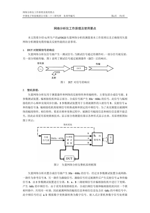
图1DUT 对信号的响应2.整机原理:矢量网络分析仪用于测量器件和网络的反射特性和传输特性,主要包括合成信号源、S 参数测试装置、幅相接收机和显示部分。
合成信号源产生30k~6GHz的信号,此信号与幅相接收机中心频率实现同步扫描;S参数测试装置用于分离被测件的入射信号R、反射信号A 和传输信号B;幅相接收机将射频信号转换成频率固定的中频信号,为了真实测量出被测网络的幅度特性、相位特性,要求在频率变换过程中,被测信号幅度信息和相位信息都不能丢失,因此必须采用系统锁相技术;显示部分将测量结果以各种形式显示出来。
其原理框图如图2所示:图2矢量网络分析仪整机原理框图矢量网络分析内置合成信号源产生30k~6GHz的信号,经过S参数测试装置分成两路,一路作为参考信号R,另一路作为激励信号,激励信号经过被测件后产生反射信号A和传输信号B,由S参数测试装置进行分离,R、A、B三路射频信号在幅相接收机中进行下变频,产生4kHz的中频信号,由于采用系统锁相技术,合成扫频信号源和幅相接收机同在一个锁相环路中,共用同一时基,因此被测网络的幅度信息和相位信息包含在4kHz的中频信号中,此中频信号经过A/D模拟数字变换器转换为数字信号,嵌入式计算机和数字信号处理器(DSP)从数字信号中提取被测网络的幅度信息和相位信息,通过比值运算求出被测网络的S参数,最后把测试结果以图形或数据的形式显示在液晶屏幕上。
◆合成信号源:由3~6GHz YIG振荡器、3.8GHz介质振荡器、源模块组件、时钟参考和小数环组成。
◆测试装置:由定向耦合器和开关构成,用于分离反射信号和入射信号。
Signaling Analyzer使用指南

Agilent Signaling Analyzer快速使用指南――DNA之8端口E1模块快速使用参考 安捷伦J6801A/B系列信令分析软件(Signaling Analzyer)由Signaling Analyzer和Network Analyzer两个软件组成。
进行软件安装时,如果需要连接J6801A/B硬件进行测试,则需要安装Network Analyzer和Signaling Analyzer两个软件;如果只需要查看Log,则只需要安装Signaling Analyzer软件。
进入CD安装Signaling Analyzer和Network Analyzer,并且输入正确的协议授权License Code。
可能安装每一个软件后,会提示您重新启动电脑应用配置,请根据提示重新启动电脑完成配置。
完成安装后,桌面出现Signaling Analyzer Real Time Mode、Signaling Analyzer Offline Mode、Analyzer Hardware(Select LIM)等快捷方式,分别可以进入“信令分析实时模式”、“信令分析后分析模式”、“进入硬件连接功能”。
通过启动Agent Config(位于操作系统开始菜单->程序->Agilent->Network Analyzer Solutions->Utilities->Agent Config)进入J6801A/B的IP连接配置。
测试用电脑和J6801A/B利用LAN进行连接。
通过Analyzer Hardware快捷方式可以看到仪表的IP地址,默认为172.30.1.xxx,之后将PC机的IP地址设置为与仪表IP地址在同一个网段即可。
1、运行Signaling Analzyer软件Signaling Analyzer Real Time Mode,进入配置界面1、这里可以看到当前连接的DNA(J6801A)模块列表。
Agilent 4395A 网络 频谱 阻抗分析仪数据手册说明书
Network Measurement1.At relative to 0 dBm output, 50 MHz,23 °C ±5 °C /HP-Agilent-4395A-Spectrum-Network-Analyzer.aspx To buy, sell, rent or trade-in this product please click on the link below:2Network MeasurementcontinuedReceiver CharacteristicsInput characteristicsFrequency range . . . . . . . . . . . . . . . . . . . . . . . . . . . . . . . . . . . . . . . . . . .10 Hz to 500 MHzInput attenuator . . . . . . . . . . . . . . . . . . . . . . . . . . . . . . . . . . . . . . . . .0 to 50 dB, 10 dB stepFull scale input level (R, A, B)Attenuator setting (dB) Full scale input level0–10 dBm100 dBm20+10 dBm30+20 dBm40+30 dBm50+30 dBmIF bandwidth (IFBW)2, 10, 30, 100, 300, 1 k, 3 k, 10 k, 30 kHzNote: The IFBW should be set to less than 1/5 of the lowest frequency inthe sweep range.Noise level (referenced to full scale input level, 23 °C ±5 °C)at 10 Hz ≤frequency < 100 Hz, IFBW = 2 Hz . . . . . . . . . . . . . . . . . . . . . .–85 dB (SPC)at 100 Hz ≤frequency < 100 kHz, IFBW = 10 Hz . . . . . . . . . . . . . . . . . . . . . . . . .–85 dBat 100 kHz ≤frequency, IFBW = 10 Hz . . . . . . . . . . . . . . . . . . . . . . . . . . . . . .-–115 dBInput crosstalkfor input R + 10 dBm input, input attenuator: . . . . . . . . . . . . . . . . . . . . . . . . . . . . .20 dBfor input A, B input attenuator: . . . . . . . . . . . . . . . . . . . . . . . . . . . . . . . . . . . . . . . . .0 dBat < 100 kHzR through A, B . . . . . . . . . . . . . . . . . . . . . . . . . . . . . . . . . . . . . . . . . . . . . .< –100 dBothers . . . . . . . . . . . . . . . . . . . . . . . . . . . . . . . . . . . . . . . . . . . . . . .< –100 dB (SPC)at ≥100 kHzR through A, B . . . . . . . . . . . . . . . . . . . . . . . . . . . . . . . . . . . . . . . . . . . . .< –120 dBothers . . . . . . . . . . . . . . . . . . . . . . . . . . . . . . . . . . . . . . . . . . . . . . .< –120 dB (SPC)Source crosstalk (for input A, B)(typical for input R)at + 10 dBm output, < 100 kHz, input attenuator: 0 dB . . . . . . . . . . . . . . . . .< –100 dBat + 10 dBm output, ≥100 kHz, input attenuator: 0 dB . . . . . . . . . . . . . . . . .< –120 dBMultiplexer switching impedance changeat input attenuator 0 dB . . . . . . . . . . . . . . . . . . . . . . . . . . . . . . . . . . . . . . . .< 0.5% (SPC)at input attenuator 10 dB and above . . . . . . . . . . . . . . . . . . . . . . . . . . . . . .< 0.1% (SPC)Connector . . . . . . . . . . . . . . . . . . . . . . . . . . . . . . . . . . . . . . . . . . . . . . . . . . . .Type-N femaleImpedance . . . . . . . . . . . . . . . . . . . . . . . . . . . . . . . . . . . . . . . . . . . . . . . . . . . .50 ΩnominalReturn lossInput attenuator0 dB10 dB20 dB to 50 dB10 Hz ≤frequency < 100 kHz25 dB125 dB125 dB1100 kHz ≤frequency ≤100 MHz25 dB125 dB25 dB1100 MHz < frequency15 dB115 dB15 dB1Maximum input level+30 dBm (at input attenuator: 40 dB or 50 dB)Maximum safe input level+30 dBm or ±7 Vdc (SPC)1.SPC34Absolute amplitude accuracy (R, A, B)at –10 dBm input, input attenuator:10 dB, frequency ≥100 Hz, IFBW ≤3 kHz, 23 °C ±5 °C, . . . . . . . . . . . .< ±1.5 dB Ratio accuracy (A/R, B/R) (typical for A/B)at –10 dBm input, input attenuator:10 dB, IFBW ≤3 kHz, 23 °C ±5 °C, . . . . . . . . . . . . . . . . . . . . . . . . . . . . . . .< ±2 dB Dynamic accuracy (A/R, B/R) (typical for A/B)Input level Dynamic accuracy 1(relative to full scale input level)frequency ≥100 Hz 0 dB ≥input level > –10 dB ±0.4 dB –10 dB ≥input Level ≥–60 dB ±0.05 dB –60 dB > input level ≥–80 dB ±0.3 dB –80 dB > input level ≥–100 dB ±3 dB Figure 1-1. Magnitude dynamic accuracy Residual responses . . . . . . . . . . . . . . . . . . . . . . . . . . . . . . . . . . .< –80 dB full scale (SPC)Trace noise (A/R, B/R, A/B)at 50 MHz, both inputs: full scale input level –10 dB, IFBW = 300 Hz . . . . . . . . . . . . . .< 0.005 dB rms (SPC)Stability (A/R, B/R, A/B) . . . . . . . . . . . . . . . . . . . . . . . . . . . . . . . .< ±0.01 dB/°C (SPC)Phase characteristics Measurements format . . . . . . . . . . . . . . . . . . .Standard format, expanded phase format Frequency response (deviation from linear phase) (A/R, B/R) (SPC for A/B) at –10 dBm input, input attenuator: 10 dB, IFBW ≤3 kHz, 23 °C ±5 °C . . . . . .< ±12°Dynamic accuracy (A/R, B/R) (SPC for A/B)Input level Dynamic accuracy 1(relative to full scale input level)frequency ≥100 Hz 0 dB ≥input level > –10 dB ±3°–10 dB ≥input Level ≥–60 dB ±0.3°–60 dB > input level ≥–80 dB ±1.8°–80 dB > input level ≥–100 dB ±18°Magnitude Characteristics1.R input level (B input level for A/B) = fullscale input level –10 dB, IFBW = 10 Hz,23 °C ± 5 °CInput level (dB)Magnitude dynamic accuracy D y n a m i c a c c u r a c y (d B )Spec Typical5Figure 1-2. Phase dynamic accuracyTrace noise (A/R, B/R, A/B)at 50 MHz, both inputs:full scale input level –10 dB, IFBW = 300 Hz . . . . . . . . . . . . . . . . .< 0.04°rms (SPC)Stability (A/R, B/R, A/B) . . . . . . . . . . . . . . . . . . . . . . . . . . . . . . . . . . .< ±0.1 °/°C (SPC)Group delay characteristicsAperture [Hz] . . . . . . . . . . . . . . . . . . . . . . . . . . . . . . . . . . . . . . . . . . .0.25% to 20% of span AccuracyIn general, the following formula can be used to determine the accuracy, in seconds,of a specific group delay measurement: . . . . . . . . . . . .Phase accuracy (degree)Aperture(Hz) x 360 (degree)Sweep characteristicsSweep type . . . . . . . . . . . . . . . . .Linear frequency, log frequency, power, list frequency Sweep direction . . . . . . . . . . . . . . . . . . . . . . . . . . . . . . . . . . . . . . . . . .Upper direction only Trigger type . . . . . . . . . . . . . . . . . . . . . . . . . .Hold, single, number of groups, continuous Trigger source . . . . . . . . . . . . . . . . . . . .Internal (free run), external, manual, GPIB (bus)Event trigger . . . . . . . . . . . . . . . . . . . . . . . . . . . . . . . . . . . . . . . . . . . . . .On point, on sweepInput level (dB)Phase dynamic accuracyD y n a m i c a c c u r a c y (d e g r e e )Spec Typical6Frequency characteristics Frequency range . . . . . . . . . . . . . . . . . . . . . . . . . . . . . . . . . . . . . . . . . . .10 Hz to 500 MHz Frequency readout accuracy . . . . . . . .±((freq readout [Hz ]) x (freq ref accuracy [1]) + RBW [Hz ] + SPAN [Hz ])) [Hz ]where NOP means number of display points NOP -1Frequency reference (Option 4395A-800)Accuracy at 23 °C ±5 °C, referenced to 23 °C . . . . . . . . . . . . . . . . . . . . . . . . . . . . .< ±5.5 ppm Aging . . . . . . . . . . . . . . . . . . . . . . . . . . . . . . . . . . . . . . . . . . . . .< ±2.5 ppm/year (SPC) Initial achievable accuracy . . . . . . . . . . . . . . . . . . . . . . . . . . . . . . . .< ±1.0 ppm (SPC) Temperature stability at 23 °C ±5 °C, referenced to 23 °C . . . . . . . . . . . . . . . . . . . . . . . . .< ±2 ppm (SPC) Precision frequency reference (Option 4395A-1D5) Accuracy at 0 °C to 40 °C, referenced to 23 °C . . . . . . . . . . . . . . . . . . . . . . . . . . .< ±0.13 ppm Aging . . . . . . . . . . . . . . . . . . . . . . . . . . . . . . . . . . . . . . . . . . . . . . . . .< ±0.l ppm/year (SPC)Initial achievable accuracy . . . . . . . . . . . . . . . . . . . . . . . . . . . . . . . . .< ±0.02 ppm (SPC)Temperature stability at 0 °C to 40 °C, referenced to 23 °C . . . . . . . . . . . . . . . . . . . . . . . .< ±0.01 ppm (SPC)Resolution bandwidth (RBW)Range 3 dB RBW at span > 0 . . . . . . . . . . . . . . . . . . . . . . . . . . . . . .1 Hz to 1 MHz, 1-3 step 3 dB RBW at span = 0 . . . . . . . . . . . .3 k, 5 k, 10 k, 20 k, 40 k, 100 k, 200 k, 400 k, 800 k, 1.5 M, 3 M, 5 MHz Selectivity (60 dB BW/3 dB BW)at span > 0 . . . . . . . . . . . . . . . . . . . . . . . . . . . . . . . . . . . . . . . . . . . . . . . . . . . . . . . .< 3Mode . . . . . . . . . . . . . . . . . . . . . . . . . . . . . . . . . . . . . . . . . . . . . . . . . . . . .Auto or manual Accuracy at span > 0 . . . . . . . . . . . . . . . . . . . . . . . . . . . . . . . . . . . . . . . . . . . . . . . . . . . .< ±10%at span = 0 . . . . . . . . . . . . . . . . . . . . . . . . . . . . . . . . . . . . . . . . . . . . . . . . . . . .< ±30%Video bandwidth (VBW)Range at span > 0 . . . . . . . . . . . . . . . .3 MHz to 3 MHz, 1-3 step, 0.003 ≤VBW/RBW ≤1Noise sidebands Offset from carrier Noise sidebands ≥1 kHz < –95 dBc/Hz ≥100 kHz < –108 dBc/Hz Figure 1-3. Noise sidebandsSpectrum Measurement Frequency offset [Hz]N o i s e s i d e b a n d [d B c /H z ]Spec Typical7Amplitude range . . . . . . . . . . . . . . . . . . . . . . . . . .displayed average noise level to +30 dBm Reference value setting range . . . . . . . . . . . . . . . . . . . . . . . . . . . . . .–100 dBm to +30 dBm Level accuracy at –20 dBm input, 50 MHz, input attenuator: 10 dB, 23 °C ±5 °C . . . . . . . . . . .< ±0.8 dB Frequency response at -20 dBm input, input attenuator: 10 dB, referenced to level at 50 MHz, 23 °C ±5 °C frequency ≥100 Hz . . . . . . . . . . . . . . . . . . . . . . . . . . . . . . . . . . . . . . . . . . . . . .< ±1.5 dB frequency < 100 Hz . . . . . . . . . . . . . . . . . . . . . . . . . . . . . . . . . . . . . . . . . . . . . .< ±1.3 dB Amplitude fidelity 1Log scale 2Range Amplitude fidelity (dB to reference input lever [dB][dB]0 to –30±0.05–30 to –40±0.07–40 to –50±0.15–50 to –60±0.35–60 to –70±0.8–70 to –80±1.8Linear scale 2 . . . . . . . . . . . . . . . . . . . . . . . . . . . . . . . . . . . . . . . . . . . . . . . . . . . . . . . . . . .< ±3%Displayed average noise level at reference value ≤–40 dBm, input attenuator: auto or 0 dB at frequency ≥1 kHz . . . . . . . . . . . . . . . . . . . . . . . . . . . . . . . . . . . . . . . . . . . .–120 dBm/Hz at ≥100 kHz . . . . . . . . . . . . . . . . . . . . . . . . . . . . . . . . . . . . . . . . . . . . . . . . . . .–133 dBm/Hz at ≥10 MHz . . . . . . . . . . . . . . . . . . . . . . . . . . . . .(–145 + frequency/100 MHz) dBm/Hz 3Figure 1-4. Typical displayed average noise level Amplitude Characteristics1.Fidelity shows an extent of nonlinearity referenced to the reference input level.2.RBW = 10 Hz, –20 dBm ≤reference value ≤+30 dBm, reference input level = full scale input level –10 dB, 23 ±5 °C3. At start frequency ≥10 MHzNote: Refer to Input attenuator part for the definition of full scale input level.Frequency offset [Hz]A v e r a g e n o i s e l e v e l [d B m /H z ]SpecTypical8Figure 1-5. Typical on-screen dynamic range (center: 100 MHz)Spurious responses Second harmonic distortion at single tone input with full scale input level –10 dB, input signal frequency ≥100 kHz . . . . . . . . . . . . . . . . . . . . . . . . . . . . . . . . . . . . . . . . . . .< –70 dBc, < –75 dBc (SPC)Third order inter-modulation distortion at two tones input with full scale input level –16 dB, separation ≥100 kHz . . . . . . . . . . . . . . . . . . . . . . . . . . . . . . . . . . . . . . . . . . . .< –75 dBc, < 80 dBc (SPC)Spurious at single tone input with full scale input level –10 dB, input signal frequency ≤500 MHz . . . . . . . . . . . . . . . . . . . . . . . . . . . . . . . . . . . . . . . . . . . . . . . . . . . . . . . . . .< –75 dBc except for the following frequency ranges:5.6 MHz ±1 MHz, 30.6 MHz ±1 MHz, 415.3 MHz ±1 MHz Residual response at reference value setting ≤–40 dBm, input attenuator: auto or 0 dB . . . . .< –110 dBmOn-screen Dynamic Range Offset frequency [Hz]O n -s c r e e n d y n a m i c r a n g e [d B c ]9Figure 1-6. Typical dynamic range at inputs R, A, and B Input attenuator Setting range . . . . . . . . . . . . . . . . . . . . . . . . . . . . . . . . . . . . . . . .0 dB to 50 dB, 10 dB step Attenuator setting (dB) Full scale input level 0–20 dBm 10–10 dBm 200 dBm 30+10 dBm 40+20 dBm 50+30 dBm Mode . . . . . . . . . . . . . . . . . . . . . . . . . . . . . . . . . . . . . . . . . . . . . . . . . . . . . . . . .Auto or manual (In auto mode, the attenuator is set to 20 dB above the reference value; this ensures that the maximum signal level after the attenuator will not be greater than –20 dBm.)Input attenuator switching uncertainty at attenuator: ≤30 dB, referenced to 10 dB . . . . . . . . . . . . . . . . . . . . . . . . . . . . .< ±1.0 dB at attenuator: ≥40 dB, referenced to 10 dB . . . . . . . . . . . . . . . . . . . . . . . . . . . .< ±1.5 dB Temperature drift . . . . . . . . . . . . . . . . . . . . . . . . . . . . . . . . . . . . . . . . . .< ±0.05 dB/°C (SPC)Scale Log 0.1 dB/div to 20 dB/div Linear at watt . . . . . . . . . . . . . . . . . . . . . . . . . . . . . . . . . . . . . . . . . . . . . . . . . . .1.0 x 10-12W/div at volt . . . . . . . . . . . . . . . . . . . . . . . . . . . . . . . . . . . . . . . . . . . . . . . . . . . . .1.0 x 10-9V/div Measurement format . . . . . . . . . . . . . . . . . . . . . . . . . . . . . . . . . . . . .Spectrum or noise (/Hz) Display unit . . . . . . . . . . . . . . . . . . . . . . . . . . . .dBm (unit of marker: dBm, dBV, dBµV, V, W)Sweep characteristics Sweep type . . . . . . . . . . . . . . . . . . . . . . . . . . . . . . . . . . . . . . . . . . . . . . . . . . . . . .Linear, list Trigger type . . . . . . . . . . . . . . . . . . . . . . . . . . .Hold, single, number of groups, continuous Trigger source . .Internal (free run), external, manual, level gate, edge gate, GPIB (bus)Sweep time (excluding each sweep setup time)RBW SPAN Typical sweep time 1 MHz 500 MHz 190 ms 100 kHz 100 MHz 300 ms 10 kHz 10 MHz 240 ms 1 kHz 1 MHz 190 ms 100 Hz 100 kHz 270 ms 10 Hz 10 kHz 2.0 s 1 Hz 1 kHz 11 s—Zero Span —1Typical Dynamic Range1.See the next item for sweep time at zero span Input level (dB)(Relative to full scale input level)D y n a m i c r a n g e (d B )Sensitivity (1 Hz RBW)Sensitivity ( 100 Hz RBW)2nd harmonic distortion 3rd order inter-modulation distortion Second Third1011Gate lengthRange . . . . . . . . . . . . . . . . . . . . . . . . . . . . . . . . . . . . . . . . . . . . . . . . . . . . . . .6 µs to 3.2 s ResolutionRange of gate length (T I )Resolution 6 µs ≤T I ≤25 ms 0.4 µs 25 ms < T I ≤64 ms 1 µs 64 ms < T I ≤130 ms 2 µs 130 ms < T I ≤320 ms 5 µs 320 ms < T I ≤1.28 s 20 µs 1.28s < T I ≤3.2 s100 µsGate lengthRange . . . . . . . . . . . . . . . . . . . . . . . . . . . . . . . . . . . . . . . . . . . . . . . . . . . . . . .2 µs to 3.2 sResolutionRange of gate delay (T d )Resolution 2 µs ≤T d ≤25 ms 0.4 µs 25 ms < T d ≤64 ms 1 µs 64 ms <T d ≤130 ms 2 µs 130 ms < T d ≤320 ms 5 µs 320 ms < T d ≤1.28 s 20 µs 1.28 s < T d ≤3.2 s100 µsAdditional amplitude errorLog scale . . . . . . . . . . . . . . . . . . . . . . . . . . . . . . . . . . . . . . . . . . . . . . . . . .< 0.3 dB (SPC)Linear scale . . . . . . . . . . . . . . . . . . . . . . . . . . . . . . . . . . . . . . . . . . . . . . . . . .< 3% (SPC)Gate control modes . . . . . . . . . . . . . . . . . . . . . . . . . . . . .Edge (positive/negative) or level Gate trigger input (external trigger input is used)Connector . . . . . . . . . . . . . . . . . . . . . . . . . . . . . . . . . . . . . . . . . . . . . . . . . . . .BNC female Level . . . . . . . . . . . . . . . . . . . . . . . . . . . . . . . . . . . . . . . . . . . . . . . . . . . . . . . . . . . . . . .TTL Gate outputConnector . . . . . . . . . . . . . . . . . . . . . . . . . . . . . . . . . . . . . . . . . . . . . . . . . . . .BNC female Level . . . . . . . . . . . . . . . . . . . . . . . . . . . . . . . . . . . . . . . . . . . . . . . . . . . . . . . . . . . . . . . .TTLSpecifications when Option 4395A-1D6 Time-Gated Spectrum Analysis is InstalledAll specifications are identical to the standard Agilent 4395A except the following items.12Measurement functions Measurement parameters Z, Y, L, C, Q, R, X, G, B, θDisplay parameters IZI, 0z , R, X, IYI, θy , G, B, I ΓI, θγ, Γx , Γy , Cp, Cs,Lp, Ls, Rp, Rs, D, QDisplay formats•Vertical lin/log scale •Complex plane•Polar/Smith/admittance chart Sweep parameters•Linear frequency sweep•Logarithmic frequency sweep •List frequency sweep•Power sweep (in dBm unit)IF bandwidth•2,10, 30, 100, 300, 1k, 3k, 10k, 30k [Hz]Calibration•OPEN/SHORT/LOAD 3 term calibration •Fixture compensation •Port extension correction Measurement port type •7-mm Output characteristicsFrequency range . . . . . . . . . . . . . . . . . . . . . . . . . . . . . . . . . . . . . . . . . .100 kHz to 500 MHz Frequency resolution . . . . . . . . . . . . . . . . . . . . . . . . . . . . . . . . . . . . . . . . . . . . . . . . .1 MHz Output impedance . . . . . . . . . . . . . . . . . . . . . . . . . . . . . . . . . . . . . . . . . . . . .50 Ωnominal Output levelwhen the measurement port is terminated by 50 Ω1 . . . . . . . . . . . . . .–56 to +9 dBm when the measurement port is open . . . . . . . . . . . . . . . . . . .0.71 mVrms to 1.26 Vrms Resolution . . . . . . . . . . . . . . . . . . . . . . . . . . . . . . . . . . . . . . . . . . . . . . . . . . . . . . . . . . .0.1 dBm Level accuracy . . . . . . . . . . . . . . . . . . . . . . . . . . . . . . . . . . . .±(A + B + 6 x F/(1.8 x 109))dB WhereA = 2 dBB = 0 dB (at 0 dBm ≤P ≤+ 15 dBm) or B = 1 dB (at –40 dBm ≤P < 0 dBm) or B = 2 dB (at –50 dBm ≤P < –40 dBm)F is setting frequency [Hz], P is output power settingOption 4395A-010Impedance measurementThe following specifications are applied when the 43961A impedance test kit is connected to the 4395A.1.When the measurement port is terminated with 50 Ω, the signal level at the measure-ment port is 6 dB lower than the signal level at the RF OUT port.13Measurement accuracy is specified at the connecting surface of the 7-mm connector of the Agilent 43961A under the following conditions:Warm up time . . . . . . . . . . . . . . . . . . . . . . . . . . . . . . . . . . . . . . . . . . . . . . . . .> 30 minutes Ambient temperature . . . . . . . . . . . . . . . . . . . . . . . . . . . . . . . . . . . . . . . . . . . .23 °C ±5 °C,within ±1 °C from the temperature at which calibration is performedSignal level (setting) . . . . . . . . . . . . . . . . . . . . . . . . . . . . . . . . . . . . . . . . . . .0 to +15 dBm Correction . . . . . . . . . . . . . . . . . . . . . . . . . . . . . . . . . . . . . . . . . . . . . . . . . . . . . . . . . . . . .ON IFBW (for calibration and measurement) . . . . . . . . . . . . . . . . . . . . . . . . . . . . . .≤300 Hz Averaging factor (for calibration and measurement) . . . . . . . . . . . . . . . . . . . . . . . . .≥8Figure 1-7. Impedance measurement accuracyIZI - θaccuracy IZI accuracy Z a = A + (B /I Z m I + C x I Z m I) x 100 [%]θaccuracy θa = sin -1(Z a /100)Where, I Z m I is I Z I measured. A, B, and C are obtained from Figure 1-7.IYI - θaccuracy IYI accuracy Y a = A + (B x I Y m I + C /I Z m I) x 100 [%]θaccuracy θa = sin -1(Y a /100)Where, I Y m I is I Y I measured. A, B, and C are obtained from Figure 1-7.Measurement Basic Accuracy(Supplemental performancecharacteristics)Test frequency [Hz]14Display LCDSize/type . . . . . . . . . . . . . . . . . . . . . . . . . . . . . . . . . . . . . . . . . . . . . . .8.4 inch color LCD Number of pixels . . . . . . . . . . . . . . . . . . . . . . . . . . . . . . . . . . . . . . . . . . . . . . . .640 x 480Effective display area . . . . . . . . . . . . . . . . . . . . . . .160 mm x 115 mm(600 x 430 dots)Number of display channels . . . . . . . . . . . . . . . . . . . . . . . . . . . . . . . . . . . . . . . . . . . . .2Format single, dual (split or overwrite)Number of traces . . . . . . . . . . . . . . . . . . . . . . . . . . . . . . . . . . . . . . . . . . . . . . . . . . . . . . . . . .For measurement . . . . . . . . . . . . . . . . . . . . . . . . . . . . . . . . . . . . . . . . . . . . . . . . .2 traces For memory . . . . . . . . . . . . . . . . . . . . . . . . . . . . . . . . . . . . . . . . . . . . . . . . . . . . . .2 traces Data math . . . . . . . . . . . . . . . . . . . . . . . . . . . . . . . . . . . . . . . . . . . . . . .gain x data – offset,gain x (data - memory) – offset,gain x (data + memory) – offset,gain x (data/memory ) – offsetData hold . . . . . . . . . . . . . . . . . . . . . . . . . . . . . . . . . . . . . . .Maximum hold, minimum hold MarkerNumber of markersMain marker . . . . . . . . . . . . . . . . . . . . . . . . . . . . . . . . . . . . . . . . . . . .l for each channel Sub-marker . . . . . . . . . . . . . . . . . . . . . . . . . . . . . . . . . . . . . . . . . . . . .7 for each channel ∆marker . . . . . . . . . . . . . . . . . . . . . . . . . . . . . . . . . . . . . . . . . . . . . . .1 for each channel Hard copyMode . . . . . . . . . . . . . . . . . . . . . . . . . . . .Dump mode only (including color dump mode)StorageBuilt-in flexible disk driveType . . . . . . . . . . . . . . . . . . . . . . . . . . . . . . . . . . . . . .3.5 inch, 1.44 MByte, or 720 KByte,1.44 MByte format is used for disk initializationMemory . . . . . . . . . . . . . . . . . . . . . . . . . . .512 KByte, can be backed up by flash memory GPIBInterface . . . . . . . . . . . . . . . . . . . . . . . . . . . . . . . . . . . . .IEEE 488.1-1987, IEEE 488.2-1987,IEC 625, and JIS C 1901-1987 standards compatible.Interface function . . . . . . . . . . . . . . . . . . . . . . . . .SH1, AH1, T6, TEO, L4, LEO, SR1, RL1,PP0, DC1, DT1, C1, C2, C3, C4, C11, E2Data transfer formats . . . . . . . . . . . . . . . . . . . . . . . . . . . . . . . . . . . . . . . . . . . . . . . . .ASCII,32 and 64 bit IEEE 754 floating point format,DOS PC format (32 bit IEEE with byte order reversed)Printer parallel portInterface . . . . . . . . . . . . . . . . . . . . . . . . . . . . . . .IEEE 1284 Centronics standard compliant Printer control language . . . . . . . . . . . . . . . . . . . . . . . . . . .PCL3 printer control language Connector . . . . . . . . . . . . . . . . . . . . . . . . . . . . . . . . . . . . . . . . . . . . . . . . . . .D-SUB (25-pin)15Common toNetwork/Spectrum/Impedance Measurement16Option 4395A-001 DC voltage/current sourceThe setting of Option 4395A-001 DC voltage/current source is independent of channel 1 and channel 2 settings.VoltageRange . . . . . . . . . . . . . . . . . . . . . . . . . . . . . . . . . . . . . . . . . . . . . . . . . . . . .–40 V to +40 V Resolution . . . . . . . . . . . . . . . . . . . . . . . . . . . . . . . . . . . . . . . . . . . . . . . . . . . . . . . . .1 mV Current limitationat voltage setting = –25 V to +25 V . . . . . . . . . . . . . . . . . . . . . . . . . . . . . .±100 mAat voltage setting = –40 V to –25 V, 25 V to 40 V . . . . . . . . . . . . . . . . . . .±20 mA CurrentRange–20 µA to -100 mA, 20 µA to 100 mAResolution . . . . . . . . . . . . . . . . . . . . . . . . . . . . . . . . . . . . . . . . . . . . . . . . . . . . . . . . . . .20 µA Voltage limitationat current setting = –20 mA to +20 mA . . . . . . . . . . . . . . . . . . . . . . . . . . . . . . .±40 V at current setting = –100 mA to –20 mA, 20 mA to 100 mA . . . . . . . . . . . . . .±25 V AccuracyVoltageat 23 °C ±5 °C . . . . . . . . . . . . . . . . . . . . . . .±(0.1% + 4 mV + I dc1[mA] x 5 [Ω] mV) Currentat 23 °C ±5 °C . . . . . . . . . . . . . . . . . . . . . . .±(0.5% + 30 µA + V dc2[V]/10 [kΩ] mA) Probe powerOutput voltage . . . . . . . . . . . . . . . . .+15 V (300 mA), –12.6 V (160 mA), GND nominal Specifications when instrument BASIC is operatedKeyboard . . . . . . . . . . . . . . . . . . . . . . . . . . . . . . . . . . . . .PS/2 style 101 English keyboard Connector . . . . . . . . . . . . . . . . . . . . . . . . . . . . . . . . . . . . . . . . . . . . . . . . . . . . . .mini-DIN 8 bit I/0 portConnector . . . . . . . . . . . . . . . . . . . . . . . . . . . . . . . . . . . . . . . . . . . . . . . . .D-SUB (15-pin) Level . . . . . . . . . . . . . . . . . . . . . . . . . . . . . . . . . . . . . . . . . . . . . . . . . . . . . . . . . . . . . . .TTL Number of input/output bit . . . . . . . . . . . . . . . . . . . . . .4 bit for input, 8 bit for outputFigure 1-8. 8 bit I/O port pin assignments24-bit I/O interfaceConnector . . . . . . . . . . . . . . . . . . . . . . . . . . . . . . . . . . . . . . . . . . . . . . . . . . .D-SUB (36-pin) Level . . . . . . . . . . . . . . . . . . . . . . . . . . . . . . . . . . . . . . . . . . . . . . . . . . . . . . . . . . . . . . . . .TTL I/O . . . . . . . . . . . . . . . . . . . . . . . . . . . . . . . . . . .8-bit for input or output, 16-bit for output Figure 1-9. 24-bit I/O interface pin assignment1.Current at DC source connector.2.Voltage at DC source connector.Table 1-1. Signal source assignmentPin No. Signal name Signal standard1GND0 V2INPUT1TTL level, pulse input (pulse width: 1 µs or above) 3OUTPUT1TTL level, latch output4OUTPUT2TTL level, latch output5OUTPUT PORT A0TTL level, latch output6OUTPUT PORT A1TTL level, latch output7OUTPUT PORT A2TTL level, latch output8OUTPUT PORT A3TTL level, latch output9OUTPUT PORT A4TTL level, latch output10OUTPUT PORT A5TTL level, latch output11OUTPUT PORT A6TTL level, latch output12OUTPUT PORT A7TTL level, latch output13OUTPUT PORT B0TTL level, latch output14OUTPUT PORT B1TTL level, latch output15OUTPUT PORT B2TTL level, latch output16OUTPUT PORT B3TTL level, latch output17OUTPUT PORT B4TTL level, latch output18OUTPUT PORT B5TTL level, latch output19OUTPUT PORT B6TTL level, latch output20OUTPUT PORT B7TTL level, latch output21I/O PORT C0TTL level, latch output22I/O PORT C1TTL level, latch output23I/O PORT C2TTL level, latch output24I/O PORT C3TTL level, latch output25I/O PORT D0TTL level, latch output26I/O PORT D1TTL level, latch output27I/O PORT D2TTL level, latch output28I/O PORT D3TTL level, latch output29PORT C STATUS TTL level, input mode: LOW, output mode: HIGH 30PORT D STATUS TTL level, input mode: LOW, output mode: HIGH 31WRITE STROBE SIGNAL TTL level, active low, pulse output(width: 10 µs; typical)32+5 V PULLUP33SWEEP END SIGNAL TTL level, active low, pulse output(width: 20 µs; typical)34+5 V+5 V, 100 mA MAX35PASS/FAIL SIGNAL TTL level, PASS: HIGH, FAIL: LOW, latch output36PASS/FAIL WRITE STROBE SIGNALTTL level, active low, pulse output(width: 10 µs; typical)1718Input and output characteristicsExternal reference inputFrequency . . . . . . . . . . . . . . . . . . . . . . . . . . . . . . . . . . . . . . . . . .10 MHz ±100 Hz (SPC)Level . . . . . . . . . . . . . . . . . . . . . . . . . . . . . . . . . . . . . . . . . . . . .-5 dBm to +5 dBm (SPC)Input impedance . . . . . . . . . . . . . . . . . . . . . . . . . . . . . . . . . . . . . . . . . . . . .50 Ωnominal Connector . . . . . . . . . . . . . . . . . . . . . . . . . . . . . . . . . . . . . . . . . . . . . . . . . . . .BNC female Internal reference outputFrequency . . . . . . . . . . . . . . . . . . . . . . . . . . . . . . . . . . . . . . . . . . . . . . . .10 MHz nominal Level . . . . . . . . . . . . . . . . . . . . . . . . . . . . . . . . . . . . . . . . . . . . . . . . . . . . . . .0 dBm (SPC)Output impedance . . . . . . . . . . . . . . . . . . . . . . . . . . . . . . . . . . . . . . . . . . .50 Ωnominal Connector . . . . . . . . . . . . . . . . . . . . . . . . . . . . . . . . . . . . . . . . . . . . . . . . . . . .BNC female Reference oven output (Option 4395A-1D5)Frequency . . . . . . . . . . . . . . . . . . . . . . . . . . . . . . . . . . . . . . . . . . . . . . . .10 MHz nominal Level . . . . . . . . . . . . . . . . . . . . . . . . . . . . . . . . . . . . . . . . . . . . . . . . . . . . . . .0 dBm (SPC)Output impedance . . . . . . . . . . . . . . . . . . . . . . . . . . . . . . . . . . . . . . . . . . .50 Ωnominal Connector . . . . . . . . . . . . . . . . . . . . . . . . . . . . . . . . . . . . . . . . . . . . . . . . . . . .BNC female External trigger inputLevel . . . . . . . . . . . . . . . . . . . . . . . . . . . . . . . . . . . . . . . . . . . . . . . . . . . . . . . . . . . . . . .TTL Pulse width (Tp) . . . . . . . . . . . . . . . . . . . . . . . . . . . . . . . . . . . . . . . . . . .≥2 µs typically Polarity . . . . . . . . . . . . . . . . . . . . . . . . . . . . . . . . . . . . . . . . .positive/negative selective Connector . . . . . . . . . . . . . . . . . . . . . . . . . . . . . . . . . . . . . . . . . . . . . . . . . . . .BNC female External program Run/Cont inputConnector . . . . . . . . . . . . . . . . . . . . . . . . . . . . . . . . . . . . . . . . . . . . . . . . . . . .BNC female Level . . . . . . . . . . . . . . . . . . . . . . . . . . . . . . . . . . . . . . . . . . . . . . . . . . . . . . . . . . . . . . .TTL Gate output (Option 4395A-1D6)Level . . . . . . . . . . . . . . . . . . . . . . . . . . . . . . . . . . . . . . . . . . . . . . . . . . . . . . . . . . . . . . .TTL Connector . . . . . . . . . . . . . . . . . . . . . . . . . . . . . . . . . . . . . . . . . . . . . . . . . . . .BNC femaleFigure 1-10. Trigger signal (external trigger input)General CharacteristicsPositive trigger signalNegative trigger signal。
网络分析仪校准件
综述:安捷伦 ENA , ENA-L , PNA , PNA-L系列网络分析仪附件包括从DC~110GHz的各种校准套件,验证套件,电缆和适配器。
校准套件误差校准步骤所要求的是通过对系统内已知的器件(校准标准件)在所关注的频率范围内进行测量从而把测试系统的系统误差表征出来。
安捷伦提供两种校准套件:机械的和电子的校准套件。
电子校准套件Ecal模块包括各种特定连接器的组合,该模块由安捷伦 ENA , ENA-L , PNA , PNA-L系列网络分析仪通过其USB端口直接控制。
在由安捷伦8753网络分析仪使用时,则通过85709B VNA 接口套件控制。
机械校准套件所有网络分析仪同轴机械校准套件都包括表征安捷伦 ENA , ENA-L , PNA , PNA-L系列网络分析仪系统性误差的精密标准装置。
许多机械校准套件还带有测试端口适配器和业内古语正确连接的扳手。
验证套件测量已知器件而非测量校准标准件是验证网络分析仪正常工作的直接方法。
安捷伦所提供的验证套件包括精密空气线,失配空气线和精密固定衰减器。
随套件提供的磁盘上由可溯源的计量数据。
标量网络分析仪附件任何标量系统的基本部件包括标量分析仪,扫频源,定向桥或耦合器,检波器。
安捷伦标量附件在与8757D网络分析仪一起使用时提供10MHz~50GHz的测量范围。
同轴机械校准套件连接器频率范围(GHz)类型 VNA 校准精度型号适用选件Type F(75 Ω) DC~3 经济 5%-1% 85039B 1A7,A6J,UK6,00M,00F,M0FType N(75 Ω) DC~3 经济 5%-1% 85039E UK6Type N(75 Ω) DC~3 标准 5%-1% 85039B 1A7,A6J,UK6Type N(50 Ω) DC~6 经济 5%-1% 85032E 1A7,A6J,UK6Type N(50 Ω) DC~9 标准 5%-1% 85032F 1A7,A6J,UK6,100,200,300,500*Type N(50 Ω) DC~18 经济 5%-1% 85054D 1A7,A6J,UK6Type N(50 Ω) DC~18 标准 2%-0.3% 85054B UK67-16 DC~7.5 标准 2% 85038A N/A7-16(female) DC~7.5 标准 2% 85038F N/A7-16(male) DC~7.5 标准 2% 85038M N/A7mm DC~6 经济 2%-0.3% 85031B 1A7,A6J,UK67mm DC~18 经济 5%-1% 85050D N/A7mm DC~18 标准 2%-0.05% 85050B N/A7mm DC~18 精密 0.3%-0.05% 85050C UK63.5mm DC~9 标准 5%-1% 85033E 1A7,A6J,UK6,100,200,300,400,500 3.5mm DC~26.5 经济 5%-1% 85052D 1A7,A6J,UK63.5mm DC~26.5 标准 3%-0.5% 85052B 1A7,A6J,UK63.5mm DC~26.5 精密 2%-0.5% 85052C 1A7,A6J,UK62.92mm DC~50 经济 11%-4% 85056K UK6,0012.4mm DC~50 经济 5%-1% 85056D UK62.4mm DC~50 标准 4%-0.5% 85056A A6J,UK61.85mm DC~67 经济 85058E 1A7,A6J,UK61.85mm DC~67 标准 85058B 1A7,A6J,UK61mm DC~110 精密 5%-1% 85059A 1A7,A6J,UK6波导机械校准套件连接器频率范围(GHz)类型 VNA 校准精度型号适用选件WR-90 8.2~12.4 精密 0.3%-0.05% X11644A 1A7,A6J,UK6WR-62 12.4~18 精密 0.3%-0.05% P11644A 1A7,A6J,UK6WR-42 18~26.5 精密 0.3%-0.05% K11644A 1A7,A6J,UK6WR-28 26.5~40 精密 0.3%-0.05% R11644A 1A7,A6J,UK6WR-22 33~50 精密 0.3%-0.05% Q11644A 1A7,A6J,UK6WR-19 40~60 精密 0.3%-0.05% U11644A 1A7,A6J,UK6WR-15 50~75 精密 0.3%-0.05% V11644A 1A7,A6J,UK6WR-10 75~110 精密 0.3%-0.05% W11644A 1A7,A6J,UK6选件描述:A6J 符合ANSI Z540校准标准 100 包括阴头至阴头适配器UK6 带测试数据的商业标准 200 包括阳头至阳头适配器00M 包括阳性接头的标准件和阳头至阳头适配器 300 包括阳头至阴头适配器00F 包括阴性接头的标准件和阴头至阴头适配器 400 增加4个3.5mm-N型适配器M0F 包括阳性接头和阴性接头的标准件及适配器 500 增加4个7mm-3.5mm适配器500* 增加4个7mm-N型适配器同轴电校准套件连接器频率范围(GHz)类型 VNA 校准精度型号适用选件Type F(75 Ω) 300KHz~3 2端口 N/A 85099C UK6,00M,00F,M0F,00AType N(75 Ω) 300KHz~3 2端口 N/A 85096C UK6, 00M,00F,M0F,00AType N(50 Ω) 300KHz~9 2端口 1%-0.1% 85092C 1A7,A6J,UK6,00M,00F,M0F,00AType N(50 Ω) 300KHz~13.5 4端口 N4431B 选件 020 1A7,A6J,UK6 Type N(50 Ω) 300KHz~18 2端口 N4690B 1A7,A6J,UK6,00M,00F,M0F,00AType N(50 Ω) 300KHz~18 4端口 N4432A 选件 020 N/A7-16 300KHz~7.5 2端口 N/A 85098C UK6, 00M,00F,M0F,00A7mm 300KHz~9 2端口 1%-0.1% 85091C 1A7,A6J,UK67mm 300KHz~18 2端口 N4696B 1A7,A6J,UK67mm 300KHz~18 4端口 N4432A 选件 030 N/A3.5mm 300KHz~9 2端口 2%-0.2% 85093C 1A7,A6J,UK6,00M,00F,M0F,00A3.5mm 300KHz~13.5 4端口 N4431B 选件 010 1A7,A6J,UK63.5mm 300KHz~20 4端口 N4433A 选件 010 N/A3.5mm 300KHz~26.5 2端口 N4691B 1A7,A6J,UK6, 00M,00F,M0F,00A 2.92mm 10MHz~40 2端口 N4692A 1A7,A6J,UK6, 00M,00F,M0F,00A 2.4mm 10MHz~50 2端口 N4693A 1A7,A6J,UK6, 00M,00F,M0F,00A 1.85mm 10MHz~67 2端口 N4694A 1A7,A6J,UK6, 00M,00F,M0F,00A VNA interface kit N/A N/A N/A 85097B 1A7,A6J,UK6,00M,00F,M0F,00A机械验证套件连接器频率范围(GHz)类型 VNA 校准精度型号适用选件Type N(50 Ω) 300KHz~18 精密 N/A 85055A 1A7,A6J,UK67mm 300KHz~6 精密 N/A 85029B 1A7,A6J,UK6,0017mm 300KHz~18 精密 N/A 85051B 1A7,A6J,UK63.5mm 300KHz~26.5 精密 N/A 85053B 1A7,A6J,UK62.4mm 0.045~50 精密 N/A 85057B 1A7,A6J,UK61.85mm 0.010~67 精密 N/A 85058V 1A7,A6J,UK6WR-28 26.5~40 精密 N/A R11645A 1A7,A6J,UK6WR-22 33~50 精密 N/A Q11645A 1A7,A6J,UK6WR-19 40~60 精密 N/A U11645A 1A7,A6J,UK6WR-15 50~75 精密 N/A V11645A 1A7,A6J,UK6WR-10 75~110 精密 N/A W11645A 1A7,A6J,UK6选件描述:1A7 符合ISO 17025校准标准 00A2 增加3.5mm 适配器A6J 符合ANSI Z540校准标准 00A3 增加2.92mm 适配器UK6 带测试数据的商业标准 00A4 增加2.4mm 适配器00M 包括阳性接头的标准件和阳头至阳头适配器 00A5 增加1.85mm 适配器00F 包括阴性接头的标准件和阴头至阴头适配器 001 增加安捷伦8702光波元件分析仪数据00A 增加N型适配器 010 四个3.5mm(f)连接器00A1 增加7-16适配器 020 四个N型50Ω(f)连接器030 四个7mm连接器本文来自仪器信息网详细参考:网络分析仪附件和校准套件综述:安捷伦 ENA , ENA-L , PNA , PNA-L系列网络分析仪附件包括从DC~110GHz的各种校准套件,验证套件,电缆和适配器。
网络分析仪原理
Intermodulation Distortion
BER EVM ACP Regrowth Constell. Eye
Full call sequence Pulsed S-parm. Pulse profiling
LCR/Z
I-V
Absol. Power
Gain/Flatness
Measurement plane
PM conversion
• Ensure good match when absorbing power (e.g., an antenna)
K P W R F M 9 7
Network Analyzer Basics
Copyright 2000
The Need for Both Magnitude and Phase
Y o u rIE E E 8 0 2 .3 X .2 5 IS D N s w itc h e d -p a c k e td a ta s tre a m is ru n n in g a t1 4 7 M B P S w ith a B E R o f1 .5 2 3 X 1 0 -9 ...
Receivers Tuners Converters
VCAs Amplifiers
VCOs VTFs Oscillators Modulators VCAtten’s
Transistors
Active
Copyright 2000
Device Test Measurement Model
Complex
DC CW Swept Swept Noise 2-tone Multi- Complex Pulsed-
freq power
Agilent RF PNA 综合指南:RF PNA 矢量网络分析仪的配置说明书
E8356A/E8801A/N3381A 300 kHz to 3 GHz E8357A/E8802A/N3382A 300 kHz to 6 GHz E8358A/E8803A/N3383A300 kHz to 9 GHzConfiguration Guide AgilentPNA RF Network AnalyzersFull S-parameter measurements•Agilent RF PNAnetwork analyzer•Test port cables, 50 ohms •Calibration kit for applicableconnector typeThis configuration guide describes standard configuration, options, accessories,upgrade kits and compatible peripherals for RF PNA vector network analyzers.This guide should be used with the Agilent RF PNA Data Sheet for a complete description of these analyzers.System configuration summary This summary lists the main components required to form a basic measurement system. Options or peripherals may be added to provide enhanced measure-ment and data storage capability.Discontinued Product Information — For Support Reference Only —World-wide Agilent sales office contact information is available at:/find/contactus1981E8356/7/8A E8801/2/3A N3381/2/3A DescriptionAvailability Availability Availability Test Set Model#-015Configurable test set XModel#-014Configurable test set XX Power Configuration Model#-1E1Extended power range Standard X X Timebase Stability Model#-1E5Add high stability timebase Standard X X Measurement Features Model#-010Time domain capability X X X Accessories Model#-1CM Rack mount kit without handles X X X Model#-1CP Rack mount kit with handles X X X N4688A USB CD R/W drive X X X N4689AUSB HubX X X Calibration Documentation Model#-UK6Commercial calibration certificate XXXwith test dataWarranty and ServiceOne, three and five year warranty and service plans are available. Contact your local Agilent sales office for details.CalibrationCalibration is available in three or five year plans. Contact your local Agilent sales office for details.2Ordering information for RF PNA Network AnalyzerAgilent RF PNA Network Analyzer Each RF PNA instrument is an integrated network analyzer with a built-in LCD display, hard and floppy disk drives,S-parameter test set and synthesized source. The analyzer has two or three 50-ohm Type-N (f) test ports. Included with each instrument is a mouse, keyboard, CD-ROM containing a copy of online help and programming documentation,anda 1-year return-to-Agilent service warranty.❐ E8356A network analyzer,300kHzto3GHz,2port, 4receiver ❐ E8357A network analyzer,300kHzto6GHz,2port, 4receiver ❐ E8358A network analyzer,300kHzto9GHz,2port, 4receiver ❐ E8801A network analyzer,300kHzto3GHz,2port, 3receiver ❐ E8802A network analyzer,300kHzto6GHz,2port, 3receiver ❐ E8803A network analyzer,300kHzto9GHz,2port, 3receiver ❐ N3381A network analyzer,300kHzto3GHz,3port, 4receiver ❐ N3382A network analyzer,300kHzto6GHz,3port, 4receiver ❐ N3383A network analyzer,300kHzto9GHz,3port, 4receiverOptions❐ Option 010time-domain capabilityFor viewing reflection and transmission responses intime or distance domain.❐ Option 014configurable test set (except E8356/7/8A) Adds front panel access to the source, the receiversand couplers. This provides the ability to improvemeasurement sensitivity for measuring low-level signals, or to add components and other peripheral instruments for a variety of measurement applications.❐ Option 015configurable test set (E8356/7/8A only) Adds front panel access to the source output and coupler input on both ports 1 and 2. Also, 35 dB step attenuators are added between the couplers and receivers. Thiscapability provides the ability to improve measurement sensitivity for measuring low-level signals, or to addcomponents and other peripheral instruments for avariety of measurement applications.❐ Option 1CM rack mount kitAdds a rack mount (part number 5063-9216) and rail kit (E3663AC) for use without handles.❐ Option 1CP rack mount kitAdds a rack mount (part number 5063-9236) and rail kit (E3663AC) for use with previously supplied handles.❐ Option 1E170 dB step attenuator (Included as standard equipment on E8356/7/8A)Adds a built-in 70 dB step attenuator to extend theoutput power range down to -85 dBm.❐ Option 1E5high-stability time base (Included as standard equipment on E8356/7/8A)Replaces standard time base reference with a higherstability unit.DocumentationThe PNA Online Help system is available within PNA instrument in the following languages: English, German, Spanish, French, Japanese, and Chinese.The PNA Service Guide and Online Help system are available on the Web: /pna Certification options❐ Option UK6Commercial calibration certificate with test dataFor online information about Agilent’sservice and support products visit:/find/tm_services3Measurement accessoriesA complete line of RF test accessories can be found inthe Agilent RF and Microwave Test Accessories Catalog (literature number 5968-4314EN) or by visiting/find/mtaAccessories are available in these connector types: 50 ohm Type-N, 3.5 mm, 7 mm, and 7-16. Test port cables and a calibration kit should be added for a complete measurement system.A verification kit is used to verify corrected system performance.Test-port cablesTest port cables are used to connect the network analyzer to the device under test.❐ N6314A50 ohm Type-N RF cable, 300 kHz to 9 GHz Includes one 610 mm (24 in) cable with male connectors (part number 8120-8862)❐ N6315A50 ohm Type-N RF cable, 300 kHz to 9 GHz Includes one 610 mm (24 in) cable with both female and male connectors (part number 8121-0027) Calibration kitsMechanical calibration kits include standards, such as opens, shorts and loads, which are measured by the network analyzer for increased measurement accuracy. Electronic calibration (ECal) kits replace mechanical calibration standards with one solid-state calibration module that is controlled by the network analyzer to present many different impedances to the test ports. Afull two-port calibration can be performed quickly with a single connection.This technique reduces operator errors and connector wear and abrasion.Choose a calibration kit for each connector type to be used.Economy, includes:• open standards (male and female)• short standards (male and female)• fixed-termination standards (male and female)• in-series adaptersStandard, includes the devices in the economy kit and adds:• connector toolsPrecision, includes the devices in the economy kit and adds:• 50 ohm airline for TRL calibration• TRL adapters• connector tools For devices with Type-N connectors Mechanical calibration kits❐ 85032F economy: 30 kHz to 9 GHz. Includes:85032-60017 Type-N (m) fixed load85032-60018 Type-N (f) fixed load85032-60013 Type-N (m) open85032-60014 Type-N (f) open85032-60016 Type-N (m) short85032-60015 Type-N (f) short❐ Option 100adds:85032-60021 Type-N (f) to Type-N (f) adapter❐ Option 200adds:85032-60019 Type-N (m) to Type-N (m) adapter❐ Option 300adds:85032-60020 Type-N (m) to Type-N (f) adapter❐ Option 500adds:85054-60001 Type-N (f) to 7 mm adapter (two included) 85054-60009 Type-N (m) to 7 mm adapter (two included)❐ 85054D economy: 45 MHz to 18 GHz. Includes: 85054-60025 Type-N (m) short85054-60026 Type-N (f) short85054-60027 Type-N (m) open85054-60028 Type-N (f) open85054-60031 Type-N (f) to 7 mm adapter85054-60032 Type-N (m) to 7 mm adapter85054-60037 Type-N (f) to Type-N (f) adapter85054-60038 Type-N (m) to Type-N (m) adapter85054-60046 Type-N (m) fixed load85054-60047 Type-N (f) fixed loadElectronic calibration kits❐ 85092C RF ECal: 300 kHz to 9 GHz, 2 ports. Includes:❐ Option MOF module with:85092-60008 Type-N (f) to Type-N (m) RF ECal module ❐ Option 00M module with:85092-60009 Type-N (m) to Type-N (m) RF ECal module ❐ Option 00F module with:85092-60010 Type-N (f) to Type-N (f) RF ECal module ❐ Option 00A adds:85054-60037 Type-N (f) to Type-N (f) adapter85054-60038 Type-N (m) to Type-N (m) adapter4For devices with 3.5 mm or SMA connectors (see Adapters section for information about the Agilent 11878A 3.5 mm adapter kit)Mechanical calibration kits❐ 85033E economy: 30 kHz to 9 GHz. Includes:85033-60016 3.5 mm (m) load85033-60017 3.5 mm (f) load85033-60018 3.5 mm (m) open85033-60019 3.5 mm (f) open85033-60020 3.5 mm (m) short85033-60021 3.5 mm (f) short8710-1761 torque wrench❐ Option 100adds:85027-60005 3.5 mm (f) to 3.5 mm (f) adapter❐ Option 200adds:85027-60007 3.5 mm (m) to 3.5 mm (m) adapter❐ Option 300 adds:85027-60006 3.5 mm (m) to 3.5 mm (f) adapter❐ Option 400adds:1250-1744 3.5 mm (f) to Type- N 50 ohm (m) adapter1250-1743 3.5 mm (m) to Type- N 50 ohm (m) adapter 1250-1745 3.5 mm (f) to Type- N 50 ohm (f) adapter1250-1750 3.5 mm (m) to Type- N 50 ohm (f) adapter ❐ Option 500adds:1250-1746 3.5 mm (m) to 7 mm adapter (two included) 1250-1747 3.5 mm (f) to 7 mm adapter (two included)❐ 85052C precision TRL: 45 MHz to 26.5 GHz. Includes: 00902-60003 3.5 mm (m) fixed load00902-60004 3.5 mm (f) fixed load85052-60006 3.5 mm (m) short85052-60007 3.5 mm (f) short85052-60008 3.5 mm (m) open85052-60009 3.5 mm (f) open85052-60032 3.5 mm (f) to 3.5 mm (f) adapter85052-60033 3.5 mm (m) to 3.5 mm (m) adapter85052-60034 3.5 mm (f) to 3.5 mm (m) adapter85052-60035 3.5 mm short TRL line85052-60036 3.5 mm long TRL line❐ 85052D economy: 45 MHz to 26.5 GHz. Includes: 00902-60003 3.5 mm (m) fixed load00902-60004 3.5 mm (f) fixed load85052-60006 3.5 mm (m) short85052-60007 3.5 mm (f) short85052-60008 3.5 mm (m) open85052-60009 3.5 mm (f) open85052-60012 3.5 mm (f) to 3.5 mm (f) adapter85052-60013 3.5 mm (f) to 3.5 mm (m) adapter85052-60014 3.5 mm (m) to 3.5 mm (m) adapter Electronic calibration kits❐ 85093C RF ECal: 300 kHz to 9 GHz, 2 ports. Includes: 85093-60008 3.5 mm (f) to 3.5 mm (m) RF ECal module ❐ Option 00M module with:85093-60009 3.5 mm (m) to 3.5 mm (m) RF ECal module ❐ Option 00F module with:85093-60010 3.5 mm (f) to 3.5 mm (f) RF ECal module ❐ Option 00A adds:85052-60012 3.5 mm (f) to 3.5 mm (f) adapter85052-60014 3.5 mm (m) to 3.5 mm (m) adapter For devices with 7 mm connectors(see A dapters section for information about Agilent 7 mm adapters)Mechanical calibration kits❐ 85031B economy: 30 kHz to 6 GHz. Includes:00909-60008 7 mm coax termination85031-60001 7 mm open/short❐ 85050C precision TRL: 45 MHz to 18 GHz. Includes: 00909-60008 7 mm coax termination85050-60003 7 mm to 7 mm airline85050-60005 7 mm to 7 mm TRL adapter85050-60006 7 mm fixed broadband load85050-80008 7 mm short85050-80009 7 mm short collet85050-80010 7 mm open❐ 85050D economy: 45 MHz to 18 GHz. Includes: 85050-60006 7 mm fixed broadband load85050-80007 7 mm short85050-80010 7 mm openElectronic calibration kits❐ 85091C RF ECal: 300 kHz to 9 GHz, 2 ports. Includes: 85091-60004 7 mm to 7 mm RF ECal module5For devices with 7-16 connectors(see Adapters section for information about the Agilent 11906B 7-16 to Type-N adapter kit)Mechanical calibration kits❐ 85038A standard: 30 kHz to 7.5 GHz. Includes: 85038-80002 7-16 (f) open85038-80003 7-16 (m) open85038-80004 7-16 (f) short85038-80005 7-16 (m) short85038-80006 7-16 (f) fixed load85038-80007 7-16 (m) fixed load8710-2175 torque wrench8710-2174 open-end wrench❐ 85038F economy: 30 kHz to 7.5 GHz. Includes: 85038-80002 7-16 (f) open85038-80004 7-16 (f) short85038-80006 7-16 (f) fixed load11906-80016 7-16 (f) to 7-16 (f) adapter❐ 85038M economy: 30 kHz to 7.5 GHz. Includes: 85038-80003 7-16 (m) open85038-80005 7-16 (m) short85038-80007 7-16 (m) fixed load11906-80015 7-16 (m) to 7-16 (m) adapter Electronic calibration kits❐ 85098C RF ECal: 300 kHz to 7.5 GHz, 2 ports. Includes:❐ Option MOF module with:85098-60007 7-16 (m) to 7-16 (f) RF ECal module ❐ Option 00F module with:85098-60009 7-16 (f) to 7-16 (f) RF ECal module❐ Option 00M module with:85098-60008 7-16 (m) to 7-16 (m) RF ECal module ❐ Option 00A adds:11906-80015 7-16 (m) to 7-16 (m) adapter11906-80016 7-16 (f) to 7-16 (f) adapter Verification kitsAll Agilent Technologies verification kits include:• precision Z°airline• mismatched airline• fixed attenuators• traceable measured data and uncertainties❐ 85055A300 kHz to 18 GHz Type-N kitIncludes attenuators, airlines and mismatch airline with data on a 3.5 inch disk for use in confirming accuracy enhanced system measurement performance, traceable to national standards. Test procedure is provided in the service manual.❐ 85053B300 kHz to 26.5 GHz 3.5 mm kitIncludes attenuators, airlines and mismatch airline with data on a 3.5 inch disk for use in confirming accuracy enhanced system measurement performance, traceable to national standards. Test procedure is provided in the service manual.6Adapters❐ 11853A 50 ohm Type-N accessory kit. Includes:1250-1472 Type-N (f) to Type-N (f) adapter (two included)1250-1475 Type-N (m) to Type-N (m) adapter (two included)11511A Type-N (f) short11512A Type-N (m) short❐ 11878A Type-N to 3.5 mm adapter kit. Includes:1250-1744 3.5 mm (f) to Type-N 50 ohm (m) adapter1250-1743 3.5 mm (m) to Type-N 50 ohm (m) adapter1250-1745 3.5 mm (f) to Type-N 50 ohm (f) adapter1250-1750 3.5 mm (m) to Type-N 50 ohm (f) adapter❐ 11524A7 mm to Type-N (f) adapter❐ 11525A7 mm to Type-N (m) adapter❐ 11906A7-16 to 7-16. Includes:7-16 (m) to 7-16 (m) adapter7-16 (f) to 7-16 (f) adapter7-16 (m) to 7-16 (f) adapter (two included)❐ 11906B7-16 to Type-N. Includes:Type-N (m) to 7-16 (m) adapterType-N (f) to 7-16 (f) adapterType-N (f) to 7-16 (m) adapterType-N (m) to 7-16 (f) adapter❐ 11854A50 ohm BNC accessory kit. Includes:1250-0929 BNC (m) short1250-1473 BNC (m) to Type-N (m) adapter (two included)1250-1474 BNC (f) to Type-N (f) adapter (two included)1250-1476 BNC (f) to Type-N (m) adapter (two included)1250-1477 BNC (m) to Type-N (f) adapter (two included)7General accessoriesUSB❐N4688A CD read/write driveProvides an external read/write CD drive with aUSB cable.❐N4489 USB HubProvides an external USB hub with at least 4-ports and a USB cable.Probe❐85024A high-frequency probeProvides high-impedance in-circuit test capability from 300 kHz to 3 GHz.Power meters and sensorsRecommended for self support, adjustments and performance tests to verify proper instrument operation.❐ E4418B single-channel power meter❐ E4419B dual-channel power meter❐ 8482A power sensor, 100 kHz to 4.2 GHz, Type-N (m), 100 mW❐ E4412A CW power sensor, 10 MHz to 18 GHz, Type-N (m), 200 mW Amplifiers1❐ 8347A RF power amplifier, 100 kHz to 3 GHz, 25 dB gain, power out: +20 dBm❐ 83006A power amplifier, 10 MHz to 26.5 GHz, 20 dB gain, power out: +18dBm to 10 GHz or +16 dBm to 20 GHz or +14 dBm to 26.5 GHz❐ 83017A power amplifier, 50 MHz to 26.5 GHz, 25 dB gain, power out: +20 dBm to 20 GHz, or +15 dBm to 26.5 GHz ❐ 83018A power amplifier, 2 to 26.5 GHz, 27 dB gain to20 GHz or 23 dB to 26.5 GHz, power out: +24 dBm to20 GHz or +21 dBm to 26.5 GHz❐ 83020A power amplifier, 2 to 26.5 GHz, 30 dB gain to20 GHz or 27 dB to 26.5 GHz, power out: +30 dBm to20 GHz or +26 dBm to 26.5 GHzCouplers❐ 87300B coaxial coupler, 1 to 20 GHz, SMA (f), 10 dB coupling❐ 87300C coaxial coupler, 1 to 26.5 GHz, 3.5 mm (f), 10 dB couplingEquipment racks and case❐ 5063-9223rack mount flange kit, for use with handles;includes handles2❐ 5063-9216rack mount kit, for use without handles; may be ordered as option 1CM❐ 5063-9236rack mount kit, for use with previously supplied handles; may be ordered as option 1CP❐ E3663AC rail kit, included with option 1CM and 1CP.❐ 9211-2658transit case1. RF connectors: 3.5 mm (f) on RF input and output; BNC (f) detector out.Type-N (f) on RF input and output for 8347A2. A PNA Series analyzer is supplied with handles.8ApplicationsMaterial measurement❐85070D High-temperature dielectric probe kitThe 85070D allow the measurement of the dielectricproperties of materials quickly and conveniently.Measurements made with this probe are nondestructiveand require no sample preparation. The dielectric probeis well suited for measurements of liquid, semisolid andflat solid materials. Measurement results can be viewedin a variety of formats (εr', εr ", tan δor Cole-Cole).The supplied software can be run in the PNA analyzeror on a PC.❐85071D Materials measurement softwareThe material software calculates the permittivity andpermeability of material samples placed in a coaxialairline or a rectangular waveguide. The measurementtechnique works well for solid materials that can bemachined to fit precisely inside a transmission line.Measurement results can be viewed in a variety offormats (εr', εr ", tan δ, µr', µr ", tan δm or Cole-Cole).The software can be run in the PNA analyzer or on a PC.Filter tuning❐N4261A Filter tuning softwareThis software will significantly reduce filter tuningtraining times and increase manufacturing throughput.Through the graphical user interface, visual trainingindicators show when the individual resonators andcouplers in a filter have been tuned within specifications.The indicators also show the user when and how to tuneeach filter element, reducing the number of times eachelement has to be re-tuned before the filter meetsspecifications.9PeripheralsThe following peripherals may be used with all RF PNAs. Other peripherals not listed here may also be compatible with these instruments.Monitors❐ VGA-compatible monitorPrinters❐ USB, LAN, parallel or serial printers withMicrosoft®Windows®2000 printer driver Interface cablesChoose the appropriate cables to connect each peripheral to the network analyzer.❐ 10833A GPIB cable, 1.0 m (3.3 ft)❐ 10833B GPIB cable, 2.0 m (6.6 ft)❐ 10833D GPIB cable, 0.5 m (1.6 ft)Upgrade kitsUpgrade kits for the E8356/7/8A, E8801/2/3A, and N3381/2/3AUpgrade kits are available to add options after initialpurchase.To order an upgrade kit for a PNA, order theanalyzer’s model number followed by a “U”, then indicate the option to be added:PNA Series RF Network Analyzer Upgrade KitsE8356/7/8AU 2-port, 4 receiver, 300kHz – 3/6/9GHz Upgrade Kits E8801/2/3AU 2-port, 3 receiver, 300kHz – 3/6/9GHz Upgrade Kits N3381/2/3AU 3-port, 4 receiver, 300kHz – 3/6/9GHz Upgrade KitsOptionsTo add options to a product, use the following ordering scheme Model:Model#U (ex: E8358AU)Model Options:Model#U-opt# (ex: E8356AU-015)❐ Option 006 for E8356A, E8801A or N3381A only.Adds 6 GHz operation. Includes installation at an Agilentservice center. Instrument calibration is required for anadditional fee.❐ Option 009 for E8356A, E8357A E8801A, E8802A, N3381A or N3382A only.Adds 9 GHz operation. Includes installation at an Agilentservice center. Instrument calibration is required for anadditional fee.❐ Option 010time-domain upgrade kit (part number E8356-60101) The serial number of the PNA to be retrofitted must bespecified when ordering this kit. Installation is notincluded.❐ Option 014for E8801/2/3A and N3381/2/3A only.Configurable test set upgrade kit (part number E8801-60103or N3381-60101, depending on model number). Includesinstallation at an Agilent service center.❐ Option 015for E8356A, E8357A or E8358A only.Configurable test set upgrade kit (part number E8356-60102).Includes installation at an Agilent service center.❐ Option 098 CPU board upgrade for E8356/7/8A built before November, 2001 (part number E8356-60103). Includesinstallation at an Agilent service center.❐ Option 099firmware upgrade (part number E8356-60103) Provides the latest revision of firmware for thePNA Series on CD-ROM. Firmware is user-installable.Installation requires USB CD-ROM drive or externalcomputer connected via LAN. The latest firmware isalso available from our web site. Visit our web page at/find/pna❐ Option 1E1 for E8801/2/3A and N3381/2/3A only.Adds a built-in step attenuator to extend the output powerrange down to -85 dBm (part number E8801-60104).Includes installation at an Agilent service center.❐ Option 1E5 for E8801/2/3A and N3381/2/3A only.Replaces standard frequency reference with a higherstability unit (part number E8801-60105). Includesinstallation at an Agilent service center.Contact your local Agilent sales or service office forfurther information.1011Literature and informationPNA RF and Microwave Brochure literature number 5968-8472E RF PNA Data Sheetliterature number 5980-1236EKey web resourcesVisit the PNA network analyzer home page at:/find/pnaFor additional application information and to download application notes, visit:/find/appcentral/find/emailupdatesGet the latest information on the products and applications you select.Microsoft ® and Windows ® are U.S. registered trademarks of Microsoft Corporation.Agilent T echnologies’ T est and Measurement Support, Services, and Assistance Agilent T echnologies aims to maximize the value you receive, while minimizing your risk and problems. We strive to ensure that you get the test and measure-ment capabilities you paid for and obtain the support you need. Our extensive support resources and services can help you choose the right Agilent products for your applications and apply them successfully. Every instrument and system we sell has a global warranty. T wo concepts underlie Agilent’s overall support policy: “Our Promise” and “Your Advantage.”Our PromiseOur Promise means your Agilent test and measurement equipment will meet its advertised performance and functionality. When you are choosing new equipment, we will help you with product information, including realistic perfor-mance specifications and practical recommendations from experienced test engineers. When you receive your new Agilent equipment, we can help verify that it works properly and help with initial product operation.Your AdvantageYour Advantage means that Agilent offers a wide range of additional expert test and measurement services, which you can purchase according to your unique technical and business needs. Solve problems efficiently and gain a competitive edge by contracting with us for calibration, extra-cost upgrades, out-of-warranty repairs, and onsite education and training, as well as design, system integration,project management, and other professional engineering services. Experienced Agilent engineers and technicians worldwide can help you maximize your produc-tivity, optimize the return on investment of your Agilent instruments and systems,and obtain dependable measurement accuracy for the life of those products.United States:Korea:(tel) 800 829 4444(tel) (080) 769 0800(fax) 800 829 4433(fax) (080) 769 0900Canada:Latin America:(tel) 877 894 4414(tel) (305) 269 7500(fax) 800 746 4866Taiwan :China:(tel) 0800 047 866(tel) 800 810 0189(fax) 0800 286 331(fax) 800 820 2816Other Asia Pacific Europe:Countries:(tel) 31 20 547 2111(tel) (65) 6375 8100Japan:(fax) (65) 6755 0042(tel) (81) 426 56 7832Email:*****************(fax) (81) 426 56 7840Contacts revised: 09/26/05For more information on Agilent Technologies’ products, applications or services,please contact your local Agilent office. The complete list is available at:/find/contactusProduct specifications and descriptions in this document subject to change without notice.© Agilent Technologies, Inc. 2003, 2004, 2006Printed in USA, July 13, 20065980-1235E/find/emailupdatesGet the latest information on the products and applications you select.Agilent Email Updates/find/agilentdirectQuickly choose and use your test equipment solutions with confidence.Agilent DirectAgilent Open/find/openAgilent Open simplifies the process of connecting and programming test systems to help engineers design, validate and manufacture electronic products. Agilent offers open connectivity for a broad range of system-ready instruments, open industry software, PC-standard I/O and global support, which are combined to more easily integrate test system development.。
- 1、下载文档前请自行甄别文档内容的完整性,平台不提供额外的编辑、内容补充、找答案等附加服务。
- 2、"仅部分预览"的文档,不可在线预览部分如存在完整性等问题,可反馈申请退款(可完整预览的文档不适用该条件!)。
- 3、如文档侵犯您的权益,请联系客服反馈,我们会尽快为您处理(人工客服工作时间:9:00-18:30)。
Range: -100 to +10 dBm
Accuracy: (E5061A Opt150, E5061A Opt250, E5062A Opt150, E5062A Opt250): Referenced to -10 dBm: ±0.303 dB at +10 dBm; ±0.144 dB at +5 dBm; ±0.090 dB at 0 dBm; ±0.068 dB at -5 dBm; ±0.055 dB at -10 dBm; ±0.065 dB at -15 dBm; ±0.073 dB at -20 dBm; ±0.080 dB at -25 dBm; ±0.087 dB at -30 dBm; ±0.095 dB at -35 dBm; ±0.103 dB at -40 dBm; ±0.111 dB at -45 dBm; ±0.121 dB at -50 dBm; ±0.134 dB at -55 dBm; ±0.150 dB at -60 dBm; ±0.174 dB at -65 dBm; ±0.211 dB at -70 dBm; ±0.270 dB at -75 dBm; ±0.371 dB at -80 dBm; ±0.546 dB at -85 dBm; ±0.841 dB at -90 dBm; ±1.334 dB at -95 dBm; ±2.141 dB at -100 dBm
10 MHz to 3.0 GHz (E5070B Opt214) ±0.65 dB at 0 dBm, 50 MHz absolute, Source Attenuator 0 dB; ±1.0 dB at 0 dBm, relative to 50 MHz reference, Source Attenuator 0 dB
Accuracy: ±5 ppm *1
Range: 300 kHz to 3.0 GHz (E5070B Opt214, Opt 1E5)
Accuracy: ±1 ppm *1
Range: 300 kHz to 1.5 GHz (E5061A Opt150, E5061A Opt250); 300 kHz to 3.0 GHz (E5062A Opt150, E5062A Opt250, E5070B Opt214)
Distribution Statement C - Distribution authorized to U. S. Government agencies and their contractors for official use or for administrative or operational purposes only, 30 October 2005. Requests for this document shall be referred to 562 CBSG/GBHA, 813 Irving-Wick Dr W, Heath, OH 43056-1199. Destruction Notice - For unclassified, limited documents, destroy by any method that will prevent disclosure of the contents or reconstruction of the document.
Accuracy: (E5070B Opt214) (Magnitude): *1 ≤0.001 dB rms, 3 MHz to 3.0 GHz
Accuracy: (E5061A Opt150, E5061A Opt250) (Phase): *1 ≤0.05 ˚rms, 300 kHz to 1 MHz; ≤0.03 ˚rms, 1 MHz to 1.5 GHz; (E5062A Opt150, E5062A Opt250) (Phase): *1 ≤0.05 ˚rms, 300 kHz to 1 MHz; ≤0.03 ˚rms, 1 MHz to 3.0 GHz
* Change Page
No.
No.
* Change No.
*Zero in this column indicates an original page
A
USAF
RF NETWORK ANALYZER E5061A OPT150, E5062A OPT250, E5070B
(AБайду номын сангаасILENT)
T.O. 33K3-4-3484-1
Test Method Verified using Shorts
Verified from +10 to -100 dBm with Step Attenuators charted at 1.195 GHz
See footnotes at end of Table. 3
T.O. 33K3-4-3484-1
Date of issue for original and changed pages are: Original......................0 ....................28 February 2010
TOTAL NUMBER OF PAGES IN THIS PUBLICATION IS 20, CONSISTING OF THE FOLLOWING:
Accuracy: *1 -5 to +10 dBm (E5061A Opt150, E5061A Opt250, E5062A Opt150, E5062A Opt250, E5062A Opt150 w/1E1); -15 to +10 dBm (E5070B Opt214) ±0.75 dB
Range: 300 kHz to 1.5 GHz, +10 dBm, IFBW at 3 kHz (E5061A Opt150, E5061A Opt250); 300 kHz to 3.0 GHz, +10 dBm, IFBW at 3 kHz (E5062A Opt150, E5062A Opt250); 3 MHz to 3.0 GHz, +10 dBm, IFBW at 3 kHz (E5070B Opt214)
Published under Authority of the Secretary of the Air Force
28 FEBRUARY 2010
T.O. 33K3-4-3484-1
INSERT LATEST CHANGED PAGES. DESTROY SUPERSEDED PAGES.
LIST OF EFFECTIVE PAGES NOTE: The portion of the text and illustrations affected by the changes is indicated by a vertical line in the outer margins of the page.
Table 1. (Cont.)
Test Instrument (TI) Characteristics
Performance Specifications
Test Method
1 CALIBRATION DESCRIPTION:
Table 1.
Test Instrument (TI) Characteristics Output Frequency
Level Accuracy
Performance Specifications
Range: 300 kHz to 1.5 GHz (E5061A Opt150, E5061A Opt250); 300 kHz to 3.0 GHz (E5062A Opt150, E5062A Opt250, E5070B Opt214)
Dynamic Accuracy
Table 1. (Cont.)
T.O. 33K3-4-3484-1
Performance Specifications
Range: 300 kHz to 1.5 GHz (E5061A Opt150, E5061A Opt250); 300 kHz to 3.0 GHz (E5062A Opt150, E5062A Opt250); 3 MHz to 3.0 GHz (E5070B Opt214)
T.O. 33K3-4-3484-1
TECHNICAL MANUAL
CALIBRATION PROCEDURE FOR
RF NETWORK ANALYZER E5061A OPT150, E5062A OPT250, E5070B
(AGILENT)
This publication replaces T.O. 33K3-4-3484-1 dated 30 September 2009.
Accuracy: *1 (E5061A Opt150, E5061A Opt250, E5062A Opt150, E5062A Opt250); ±0.8 dB at 0 dBm, 50 MHz absolute; ±1.0 dB at 0 dBm, relative to 50 MHz reference, Source Attenuator 0 dB
Measured with a Power Meter and Power Sensor
Known signal level is applied to the receiver, Phase and Magnitude noted
See footnotes at end of Table. 2